Sapphire Laser Head and Base Plate
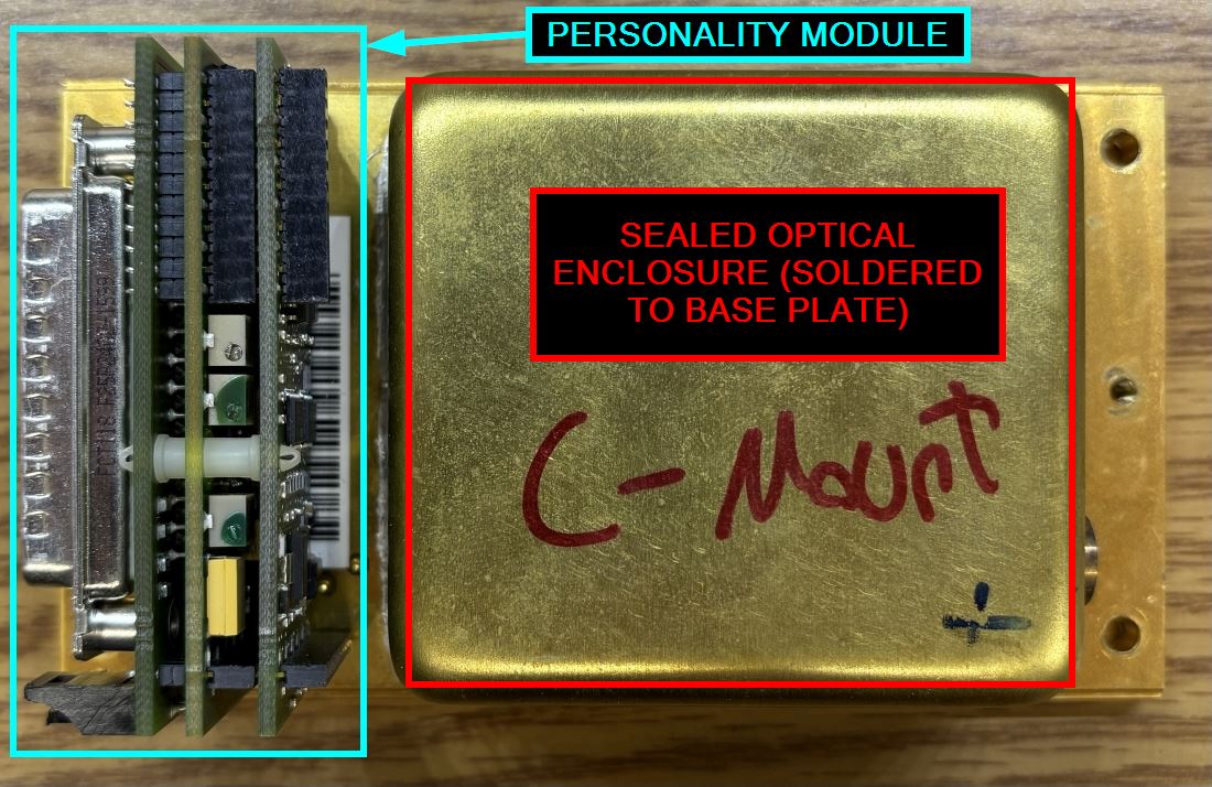
In this write-up, we'll take a deep dive into the Coherent Sapphire laser series "personality module" (also known as the OPS Headboard) as well as other aspects of the laser driver/control system. This is the information Coherent really doesn't want you to know, strap yourself in! The Sapphire series are one of Coherent's flagship lasers. They use modern and advanced OPSL technology to generate nearly any wavelength of laser light. They have numerous applications and are available in a wide variety of power levels and wavelengths. Sapphire lasers have excellent beam characteristics and are very reliable. They're often used in laboratory settings, medical devices, and many highly-specialized scientific applications. To ensure the Sapphire is not only operational, but reliable too, it's critical that several optical components are monitored and kept at the appropriate temperature. This includes the pump laser diode, BRF, SHG, etc. Additionally, the laser diode requires precise current control to operate effectively. The entire optical table (ceramic substrate) contained within the head is also actively cooled via a TEC. The Sapphire is an advanced laser system with many different electronic components that need to be monitored and controlled. Unlike most laser systems that just use a laser driver, the Sapphire splits these duties between the Sapphire OEM controller (laser driver), and the personality module contained within the laser head. The Sapphire OEM controller is connected to the laser head directly via the DB-25 connector or with a cable. We believe that most controllers should be capable of driving compatible models of Sapphire laser heads. All the information and parameters specific to the optical components within the head are stored on the personality module EEPROM. Additionally, the OEM controller is very similar across Sapphire laser head models, with only minor changes that could just be different revisions. However, we have not been able to prove exactly how cross compatible heads and controllers are, the OEM controller may contain critical head operating parameters as well. Perhaps it's more about Coherent being able to program a new controller if required. We'll focus heavily on the personality module (PM) in this writeup. Below is an image of a Sapphire laser head with the top cover removed to expose the PM.
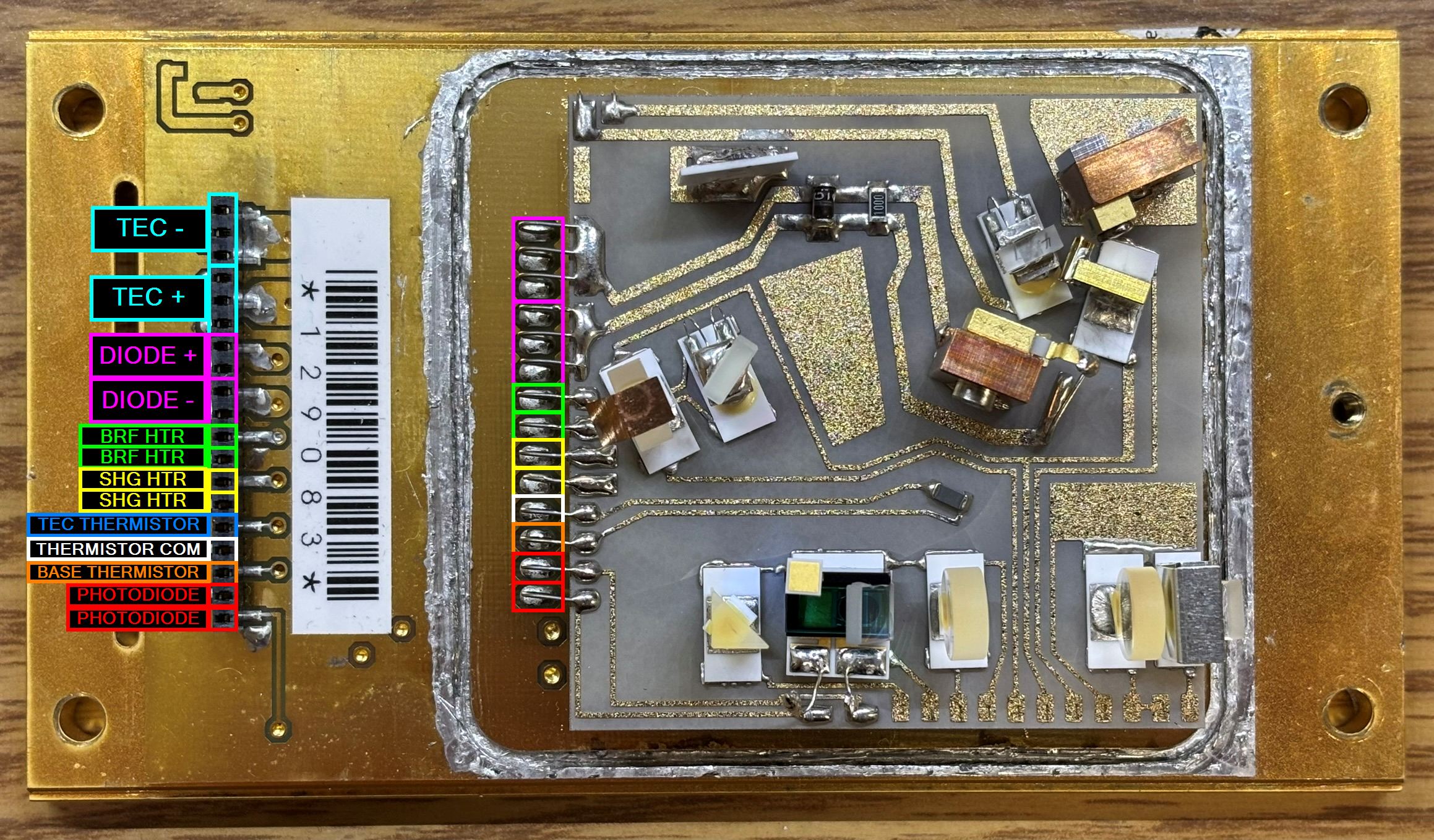
Below is an image of the Sapphire laser head with covers removed and the PM removed to expose the connector. This connector is a single-row pin header connector to which the PM board stack plugs in to. We have analyzed the connections and provided a pin-out.
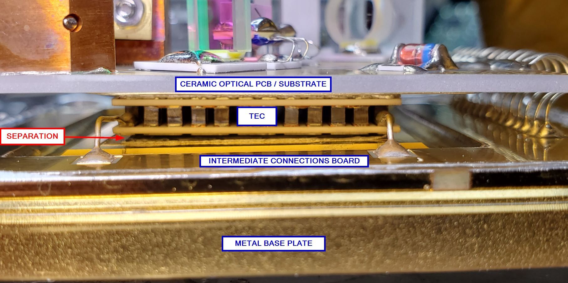
The TEC is located between the ceramic substrate and the metal base plate. The image below shows these components inside of a damaged Sapphire where the TEC has separated from the base plate due to shipping damage.
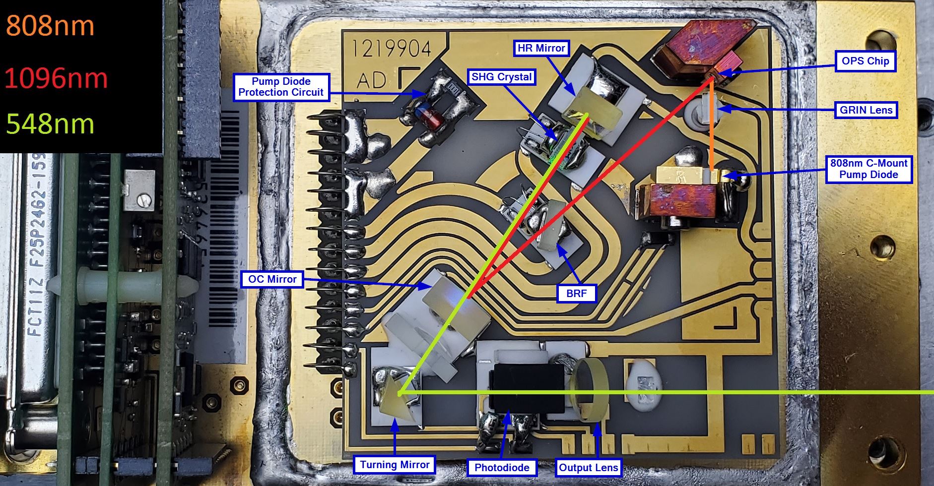
To learn more about the optical beam path and components of the Sapphire laser head, please check out the following pages on this website that go into the optical details of two different Sapphire models.
For reference, we have included an annotated image of a Sapphire 548 beam path below. Most Sapphire laser models will follow this optical configuration quite closely.
Sapphire Personality Module (OPS Headboard)
Contained within the Sapphire laser head, but not under the hermetically sealed optical enclosure, is a stack of small circuit boards. This assembly is called the personality module (PM). All coherent sapphire lasers are built in a similar manner, with only minor deviations in form factor, optical design, and bean delivery type. While there are different controller versions as well, the personality module remand relatively unchanged with different Sapphire models and variations. We believe that if we can understand and take control over the PM, it will make repairing and calibrating Sapphire lasers significantly more accessible to hobbyists and organizations looking to service their own systems. Firstly, what actually is the personality module and what role does it play. The personality module is essentially the last stage of regulation and control for the sensitive optical components contained within the laser head. The Sapphire controller does not interface directly with most of the optical components. These signals first pass through the PM.
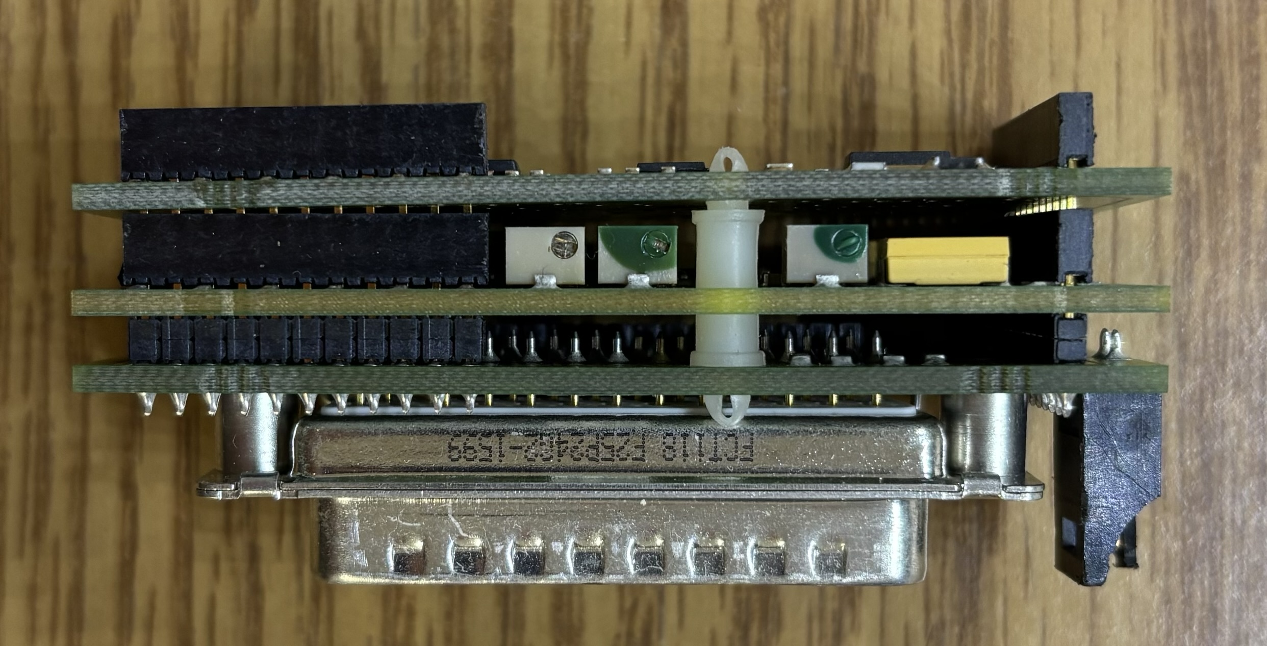
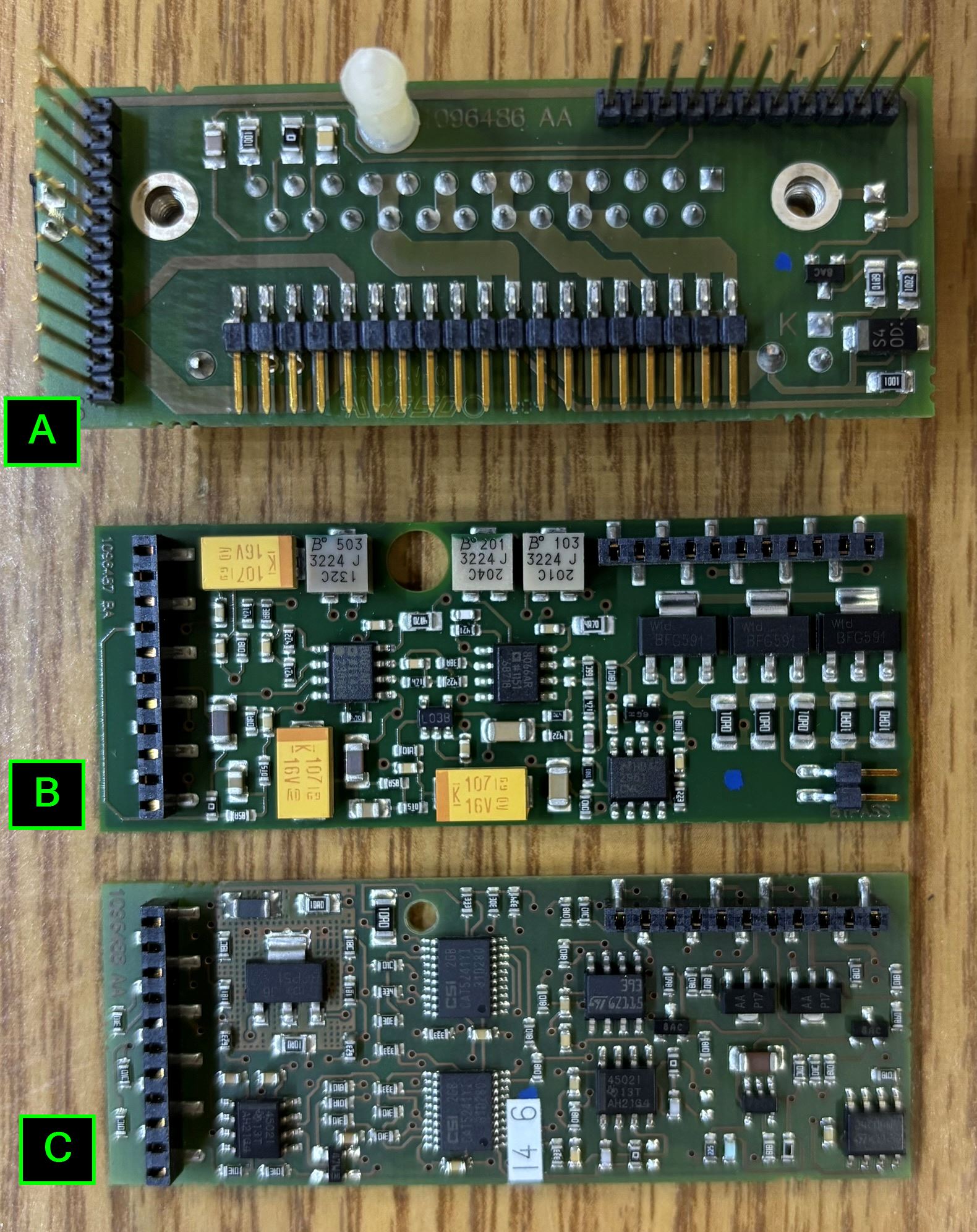
The PM is comprised of three individual boards. Two Single-row pin header connectors extend from the first board through to the last one, passing directly through the center circuit board. Below is an image of the front (component) side of all three PM boards.
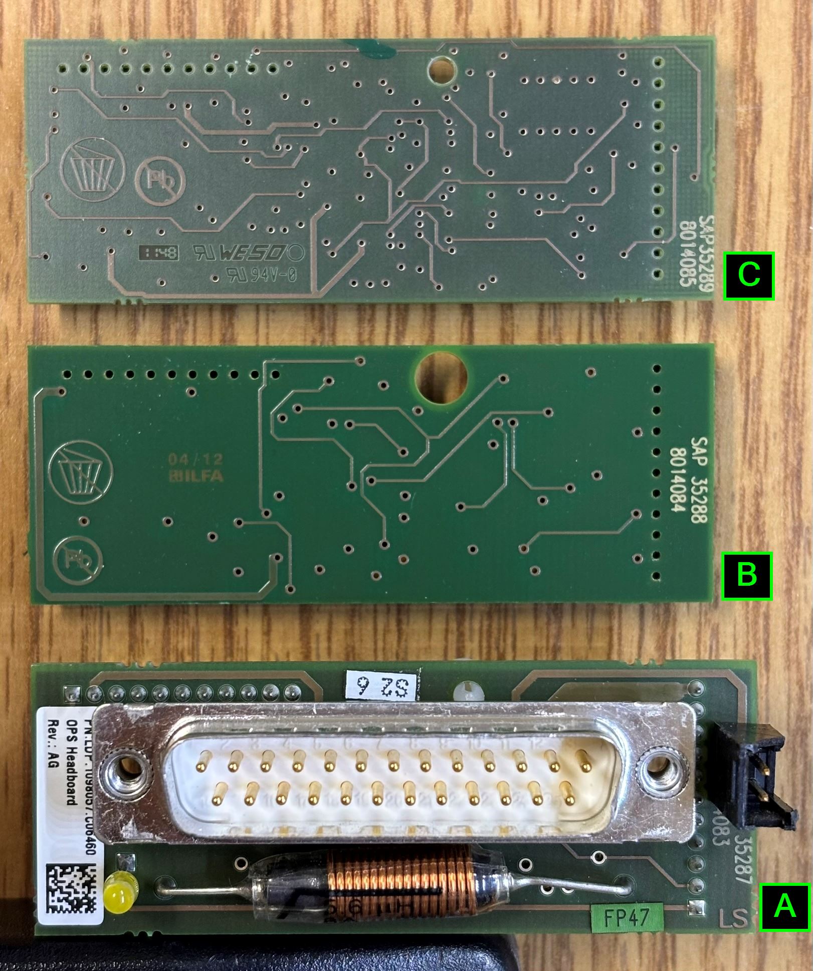
Below is an image of the back side of PM boards.
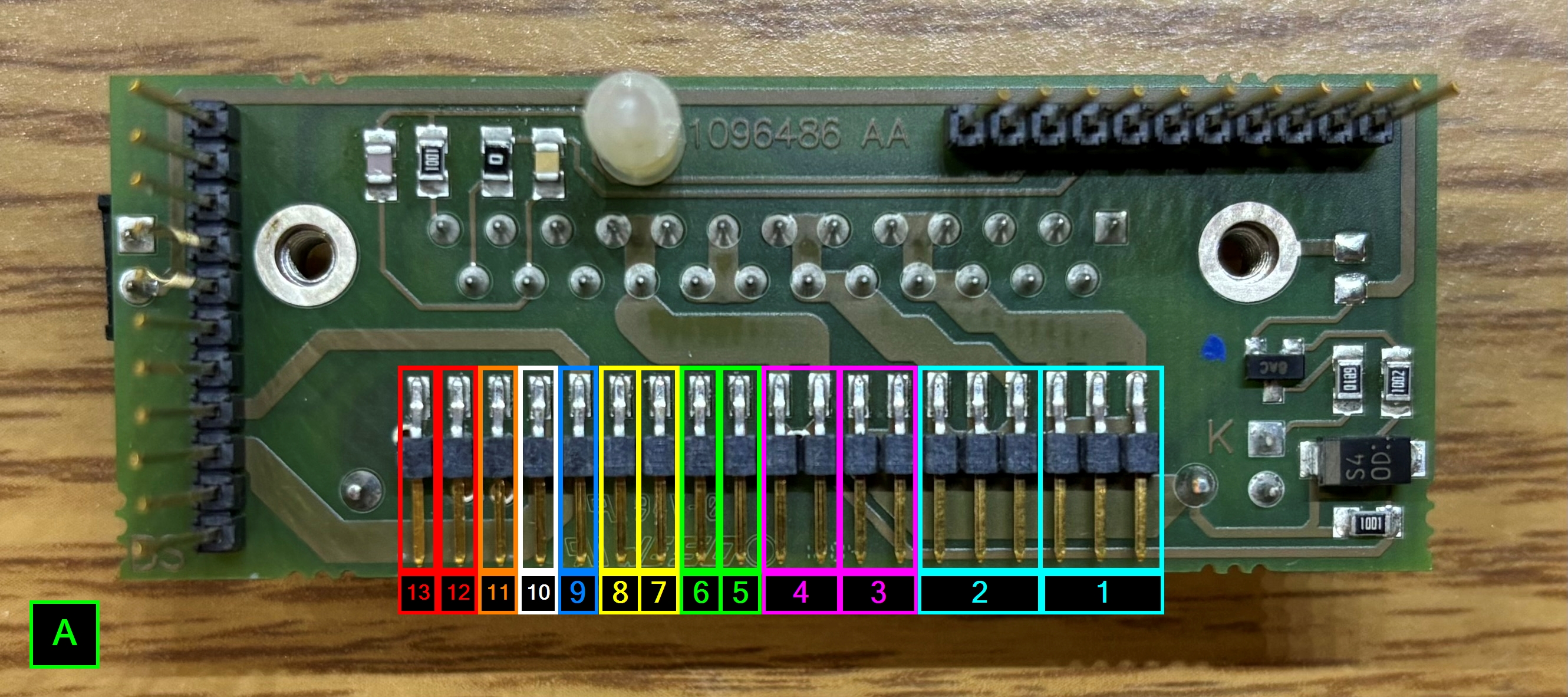
Breaking down the boards individually, we'll start with board A. This is the rearmost board that includes the DB-25 interface connector. This board has very little active circuitry and is primarily used to distribute power to the components within the laser head, and digital signals to the other boards that make up the PM. Notably, there is a 5.6 uH axial inductor located below the DB-25 connector. This inductor appears to be related to pump diode protection. The board contains 3 different single-row pin headers. Two of which extend through the other PM boards, and the bottom pin header connects to the optical baseplate. Other components on board A include the laser head power LED and fan connector. We have identified the single row header pins that mate to the single row pin header connector on the baseplate. Refer to the image of the base plate for pin functions.
Next is board B. This is the middle board that gets sandwiched between boards A and C. It contains a significant amount of active circuitry.
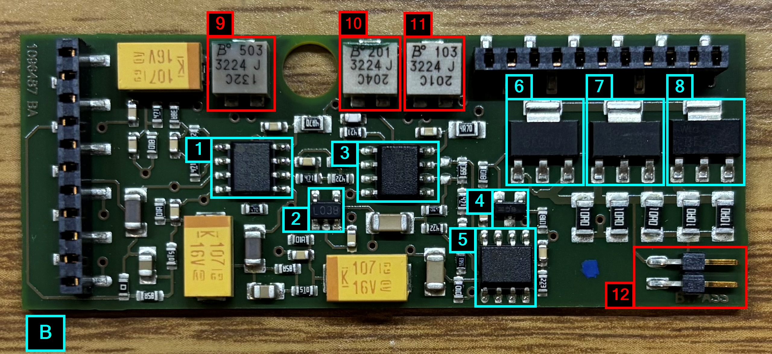
| LABEL | PART ID | DESCRIPTION | PURPOSE |
|---|---|---|---|
| 1 | AD8002AR | current feedback amplifier | diode current monitoring |
| 2 | LP2981IM5-5.0 | linear voltage regulator | |
| 3 | AD8066AR | high performance operational amplifier | |
| 4 | ELM990581BC | linear voltage regulator | |
| 5 | LP2951CM | linear voltage regulator | |
| 6 | BFG591 | NPN 7 GHz wideband transistor | |
| 7 | BFG591 | NPN 7 GHz wideband transistor | |
| 8 | BFG591 | NPN 7 GHz wideband transistor | |
| 9 | 3224J | potentiometer | |
| 10 | 3224J | potentiometer | |
| 11 | 3224J | potentiometer | |
| 12 | BYPASS JUMPER | UNKNOWN |
Lastly is board C, which contains multiple interesting components which include a couple of digital potentiometers and an EEPROM.
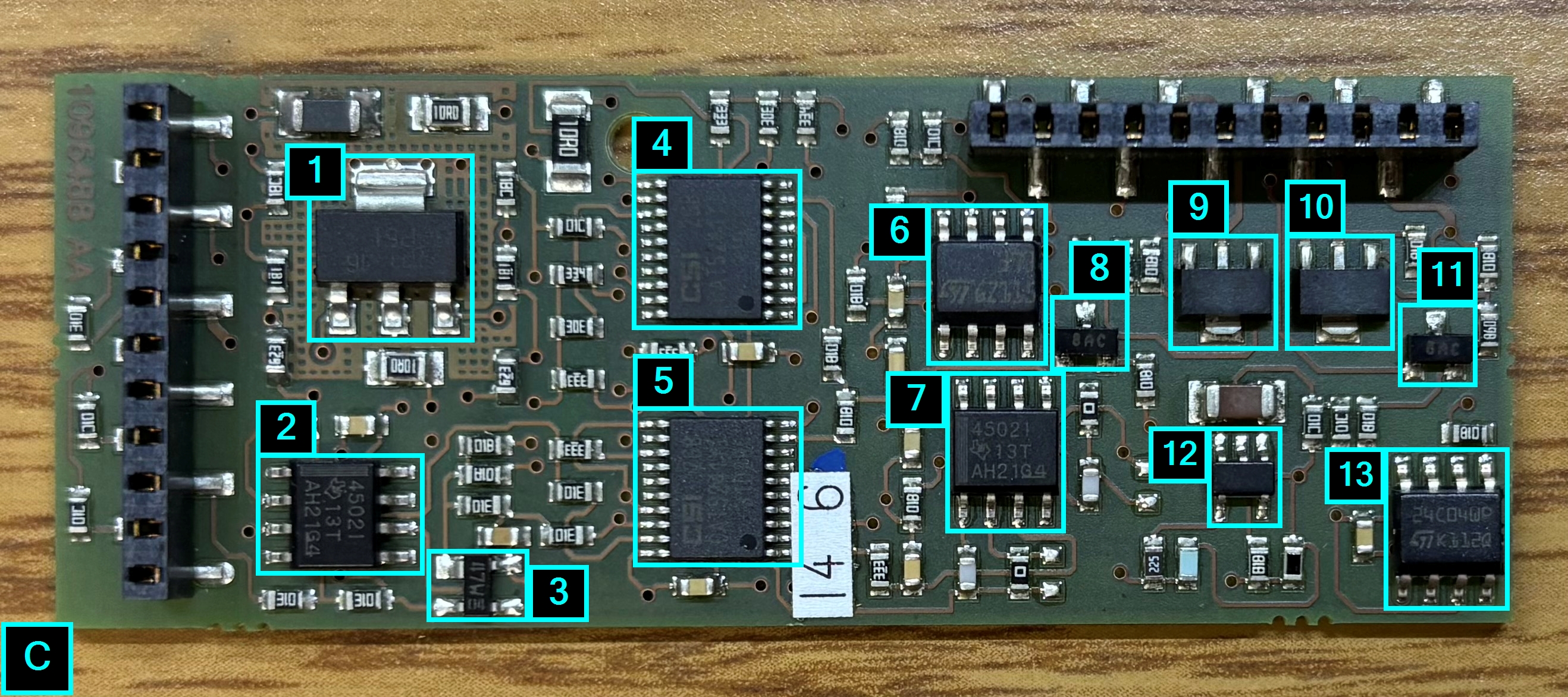
| LABEL | PART ID | DESCRIPTION | PURPOSE |
|---|---|---|---|
| 1 | BCP51 | PNP medium power transistor | |
| 2 | UNIDENTIFIED | UNKNOWN | |
| 3 | BAS40-07 | general purpose schottky diode for high speed switching | |
| 4 | CSI CAT5241 | four digital POTs with integrated control logic and 16 bytes of EEPROM memory | |
| 5 | CSI CAT5241 | four digital POTs with integrated control logic and 16 bytes of EEPROM memory | |
| 6 | LM393 | low power dual voltage comparator | |
| 7 | UNIDENTIFIED | UNKNOWN | |
| 8 | BC846CMTF | NPN epitaxial silicon transistor (needs confirmation) | |
| 9 | XC61FN4152P | voltage detector IC | |
| 10 | XC61FN4152P | voltage detector IC | |
| 11 | BC846CMTF | NPN epitaxial silicon transistor (needs confirmation) | |
| 12 | UNIDENTIFIED | UNKNOWN | |
| 13 | ST24C04 | 4 kbit (512 bytes) serial I2C bus EEPROM with user-defined block write protection | system ID and parameter storage |
Firmware Analysis
This section is a work in progress. Fields are labeled by confidence and none of it should be treated as an official Coherent specification. Portions of the page below were generated using AI based on the information collected.
We were able to de-solder and read the raw hex data from the EEPROM. The raw hex can be downloaded by clicking the link below.
Since first publishing the hex dump above, we have made substantial progress on decoding it. The data is not ASCII, it is packed binary numerics. The bulk of the decode work below was done by our friend whoiswei, who cross-referenced three Sapphire head dumps (two 488-200 heads and one 488-20) to isolate the fields. Values are stored big-endian. Numeric parameters are float32, with the exception of the wavelength field, which is a uint16 Unused space is filled with a repeating pad byte, and the pad byte differs by model class: 0x55on HP (high power) heads, 0xAA on LP (low power) heads.
| OFFSET | TYPE | FIELD | CONFIDENCE |
|---|---|---|---|
| 0x0000 | float32 | Model-class value - 40 E9 EB 85 (7.31) on HP heads, 40 C9 99 99 (6.30) on LP heads | Confirmed as a class discriminator; meaning unconfirmed |
| 0x0004 | float32 | HEADID / head serial number, stored as an integer-valued float | Probable |
| 0x0008 | uint16 | Wavelength in nm (01 E8 = 488) | Confirmed |
| 0x002A | float32 | Temperature setpoint | Probable |
| 0x002E | float32 | Temperature setpoint | Probable |
| 0x0036 | float32 | Maximum power (mW) | Confirmed |
| 0x003A | float32 | Minimum power (mW) | Confirmed |
| 0x003E | float32 | Current - per the manual's scaling, multiply by 2.5 for HP heads and by 1 for LP heads | Probable |
| 0x00FC | float32 | Total operating hours | Confirmed |
The max/min power fields are the strongest anchor in the map: on a healthy Sapphire 488-200 they read exactly 220.0 and 20.0, matching the nameplate rating. Operating-hour values observed on two 488-200 heads were 7267.391 h and 2740.230 h. Below are the first 0x60 bytes of the dump published above, annotated (Sapphire 488-200, 7267.391 Hours). The remainder of the image is 0x55 pad except for the operating-hours field at offset 0x00FC.
| OFFSET | RAW | VALUE | INTERPRETATION |
|---|---|---|---|
| 0x0000 | 40 E9 EB 85 | 7.31 | HP class marker |
| 0x0004 | 48 F6 D8 A0 | 505541.0 | HEADID |
| 0x0008 | 01 E8 | 488 | Wavelength (nm) |
| 0x000A | C1 A0 00 00 | -20.0 | UNIDENTIFIED |
| 0x000E | 42 C8 00 00 | 100.0 | UNIDENTIFIED |
| 0x0012 | BB A3 D7 0A | -0.005 | UNIDENTIFIED |
| 0x0016 | 3F 80 00 00 | 1.0 | UNIDENTIFIED |
| 0x002A | 41 98 00 00 | 19.0 | Temperature setpoint |
| 0x002E | 41 9F FF FF | 19.999998 | Temperature setpoint |
| 0x0032 | 00 78 | 120 | UNIDENTIFIED (uint16) |
| 0x0034 | 00 04 | 4 | UNIDENTIFIED (uint16) |
| 0x0036 | 43 5C 00 00 | 220.0 | Maximum power (mW) |
| 0x003A | 41 A0 00 00 | 20.0 | Minimum power (mW) |
| 0x003E | 40 33 33 33 | 2.8 | Current (× 2.5 on HP = 7.0) |
| 0x0042 | 3F 80 00 00 | 1.0 | UNIDENTIFIED |
| 0x0046 | 04 3A 0B 1C 03 CC 0B 1C 03 E8 | 1082, 2844, 972, 2844, 1000 | UNIDENTIFIED - reads cleanly as a run of five uint16s |
| 0x0050 | 3F 80 00 00 | 1.0 | UNIDENTIFIED |
| 0x0054 | 01 55 55 5A 6E 55 55 59 A9 | UNIDENTIFIED - bytes written over the pad pattern, alignment unknown | |
| 0x00FC | 45 E3 1B 21 | 7267.391 | Total operating hours |
Two observations worth recording. First, 0x002E decodes to 19.999998 rather than a clean 20.0, which suggests it is a stored or computed value rather than a hand-entered constant, while 0x002A (19.0) is exact. Second, 0x0012 and 0x0016 (-0.005 and 1.0) sit adjacent and have the shape of an offset/gain pair. This has not been verified against hardware behavior.
No checksum has been identified in the Sapphire PM data. Two independent analyses of the dumps failed to find one, and no field in the map behaves like a checksum or a duplicate copy. This is a negative result rather than proof of absence, but it is consistent across every dump examined so far. For contrast, the older Coherent CUBE heads do use a checksum, and the OBIS Core takes the opposite approach entirely: the data is stored three times over, with an additive checksum on top, in an EEPROM several times larger than the Sapphire's.
Regarding fingerprints, three independent markers separate HP from LP heads:
- Pad byte - 0x55 (HP) versus 0xAA (LP).
- The float at offset 0x0000 - 7.31 (HP) versus 6.30 (LP).
- The current scaling factor applied to offset 0x003E - 2.5 (HP) versus 1 (LP).
Speculative: because the 0x0000 value tracks model class, and because both observed values (7.31 and 6.30) land in a plausible pump-diode current range - and 2.8 × 2.5 = 7.0 on the HP head above - 0x0000 may be a current limit rather than an arbitrary model tag. Unverified.
Related Hardware Findings
- The EEPROM is not exposed on the DB-25 connector. Board inspection shows that none of the EEPROM pins - SCL and SDA in particular - are routed out to the DB-25. The working theory is that the PM reads the EEPROM locally and passes converted parameters to the OEM controller, rather than the controller reading raw EEPROM contents over the cable. The practical consequence is that you cannot sniff the PM data by tapping the head cable. A DB-25 breakout placed between head and OEM controller will reveal the analog and power lines, and whatever digital signaling exists between the two, but not the EEPROM bus itself.
- Not all internal pins are broken out from the baseplate connector to the DB-25, which limits how much of the head can be driven without removing the original PM boards.
- The digital potentiometers appear only on HP boards. A 2007-production 488-20 PM has none fitted. Their function remains unconfirmed; the two candidates raised so far are crystal heater temperature regulation and photodiode calibration.
- The crystal heaters are believed to be driven by the OEM controller rather than autonomously by the head. DB-25 pins have been traced directly back to the main laser unit, so on/off control is likely handled by the controller, either through a MOSFET or over the digital link.
On a Sapphire 488-20 LDP, one NTC is routed to pins 19 and 16, while pins 17 and 18 carry the photodiode power feedback. That NTC is not mounted next to the TEC, it is fixed to the metal base plate at the bottom of the laser head. The arrangement is unusual enough that the thermistor was initially assumed to be dead until the unit was opened and traced. This differs from the 488-200. Treat NTC and photodiode pin assignments as variant-specific and verify them per unit rather than assuming they hold across the family. The same caution applies across the wider Coherent range: on the OBIS Core, the base plate and OPS thermistor pin assignments are swapped between the 488-20 and the 532-80, and wiring one from experience with the other risks destroying the OPS chip.