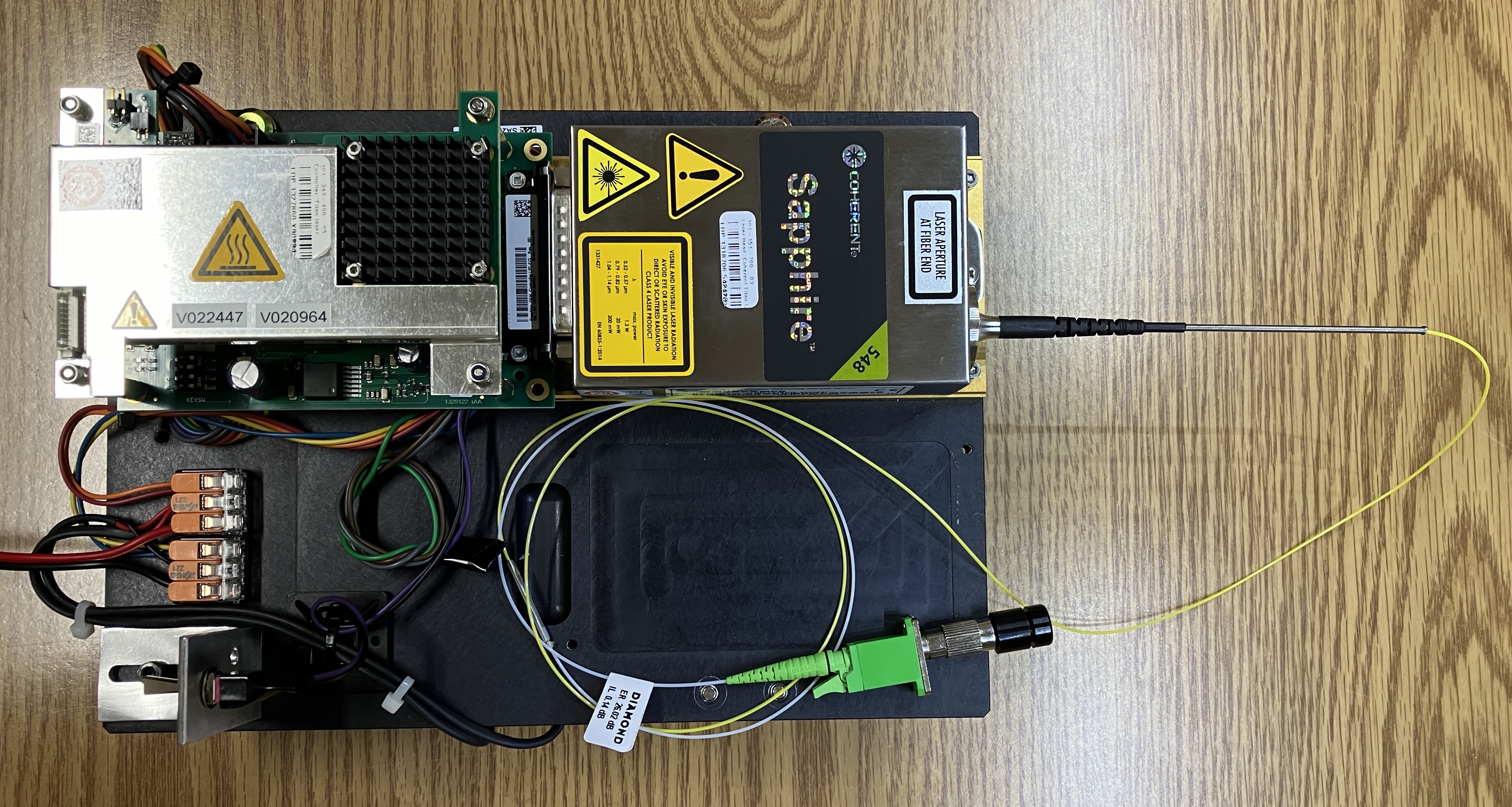
The Coherent Sapphire 548-300 is a 548nm OPSL laser system capable of a maximum output power of 300 mW. Coherent originally patented OPSL technology and implemented it in their Sapphire and OBIS series of high-end lasers. These were originally intended to replace traditional Argon Ion lasers that were significantly larger and highly inefficient. Other manufacturers are now also using OPSL technology in their lasers, most notably OSRAM with their PL-530 miniature OPSL laser module. The PL-530 is an order of magnitude smaller than the Sapphire, but works in essentially the same way using miniaturized optics and an OPS chip. 548nm is a relatively uncommon wavelength of laser light. No common gas lasers that we are aware of produce this wavelength. Some DPSS lasers come close, but OPSL technology is one of the few ways to produce this rare wavelength. The laser head itself must be mounted to a heatsink or thermally-conductive base plate, but use extra caution when securing it down as over torquing or "twisting" the base plate can cause the TEC contained within the laser head to become separated. This laser system was originally part of a DNA sequencer as an OEM component. Most DNA sequencing systems use lasers in some capacity as part of the process. DNA sequencing is a complex topic, but a very brief overview of this process is as follows: fluorescent dyes are used to label the nucleotides, a laser is used to excite these dyes as a DNA molecule passes through the system, this fluorescence is detected by the instrument and interpreted as part of the sequencing process. A pair of identical or very similar (in wavelength) Sapphire units came mounted to a thick aluminum base plate, along with their respective driver boards. Additionally, there is a heatsink mounted to the underside of the base plate along with two small fans. The laser head itself connects directly to a Coherent Sapphire driver board mounted behind it. The DB-25 connector of the driver board plugs into the DB-25 connector of the laser head. The Sapphire driver board is a dedicated module designed for OEM integration into a product, for the purpose of controlling and monitoring a Sapphire laser head. Please note that some bolts and brackets have been added to the base plate so it can support itself when placed on a flat surface. These were not part of the OEM configuration.
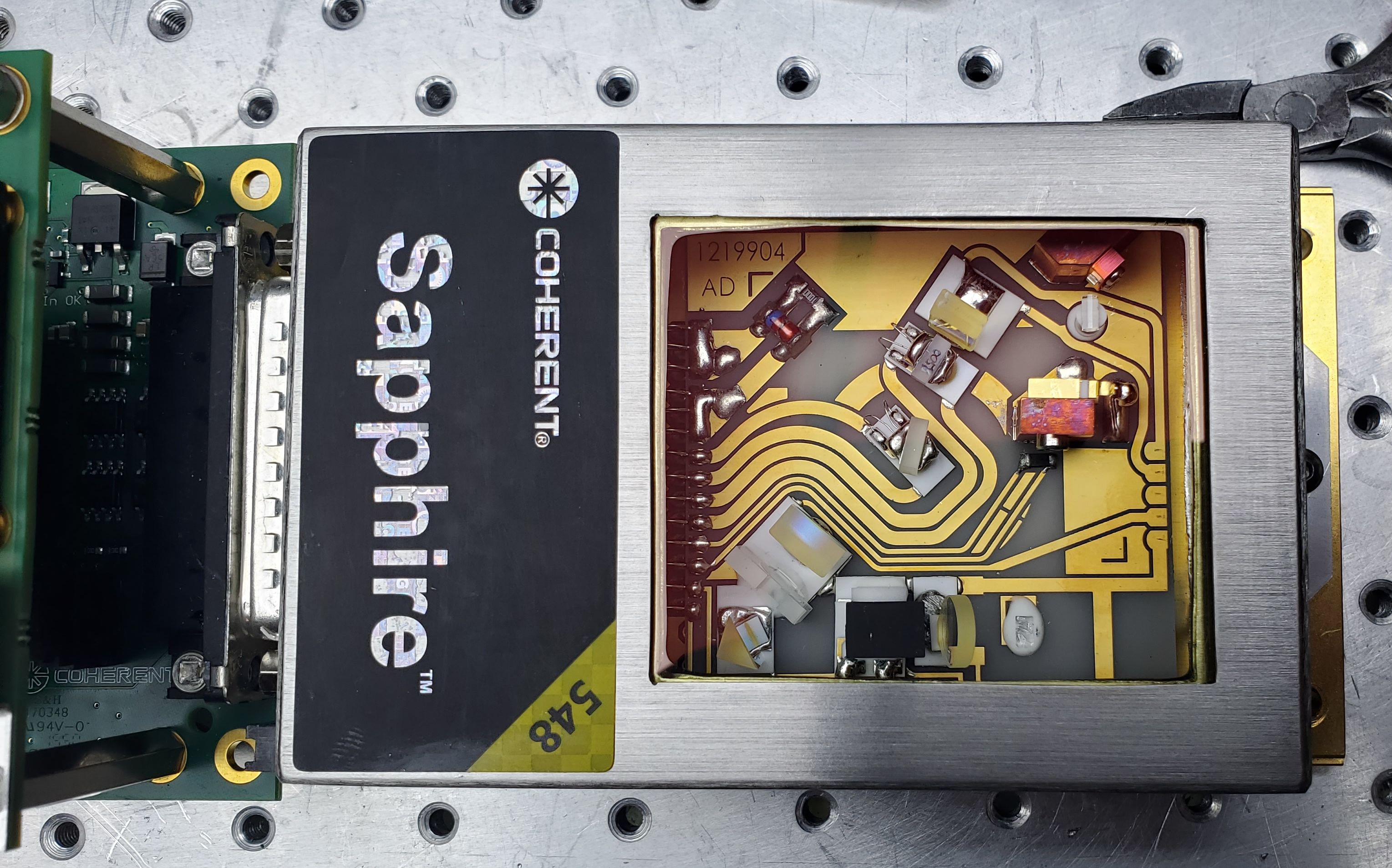
The image below is of Patrick's (Zenodilodon) Sapphire 548-300 which he repaired and modified with a glass viewing window over the optical components.
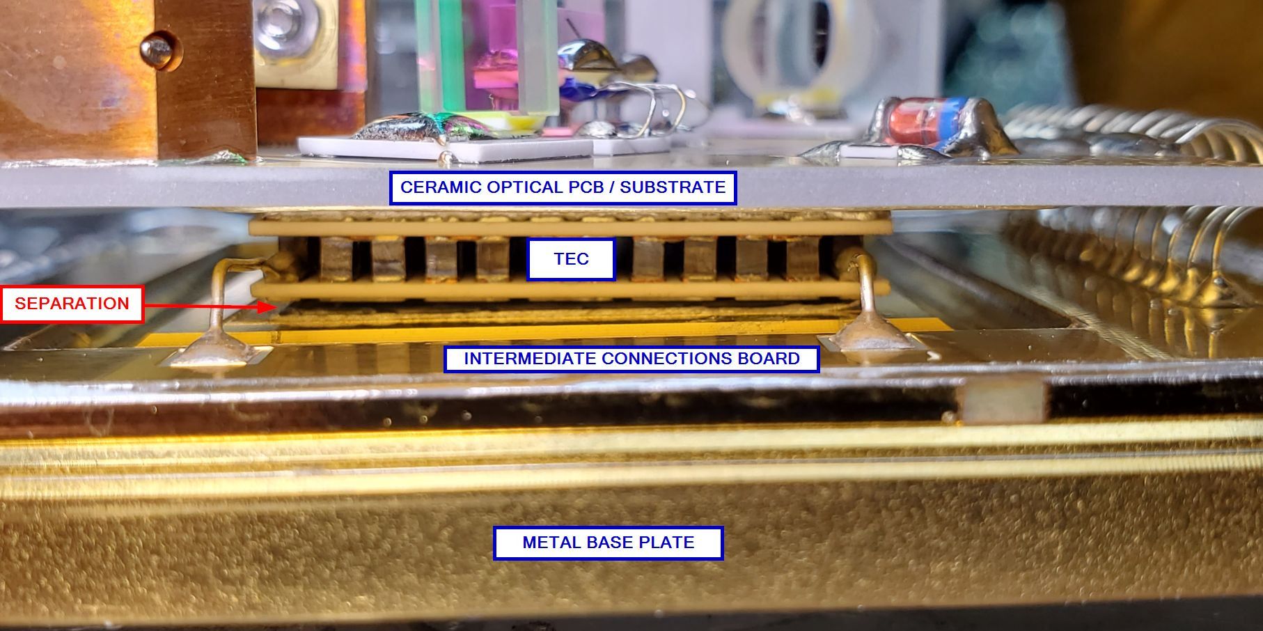
Below is an image of another Sapphire 548-300 laser head that Patrick (Zenodilodon) worked with. Likely due to rough handling during shipping, the TEC had separated from the base plate on this unit. While this is a challenging situation, it does not mean the laser head is gone for good. The TEC can be re-attached by using one of two methods. The first (less desirable) method is to apply glue between the TEC and base plate and then apply constant pressure from the top of the optical PCB directly over the TEC so it presses down on the TEC, which then presses down on the base plate. It needs to be left in this configuration for several hours to bond reliably. The preferred method that Patrick used was to apply pressure from the top as mentioned earlier, but instead use a heat gun to re-liquify the solder bond between the TEC and base plate. Specifically, he used a small section of metal tubing around the SHG crystal and then added various objects for weight on top. This provided the required pressure to secure the TEC to the base plate when the solder melted. If completed successfully, the laser head will be operational again. It is extremely important to NOT power on a Sapphire laser head if you know or suspect the TEC has separated. The controller is unaware of this condition and will increase power to the TEC without detecting a temperature change, which will eventually destroy the TEC if not caught quickly. Coherent revised this design defect in certain other Sapphire models by placing the mounting holes on tabs at each side of the laser head, closer to the center. However, even modern Sapphire laser heads can still come in the configuration with the mounting holes in each corner, so caution must still be exercised when securing a Sapphire laser head to a base plate.
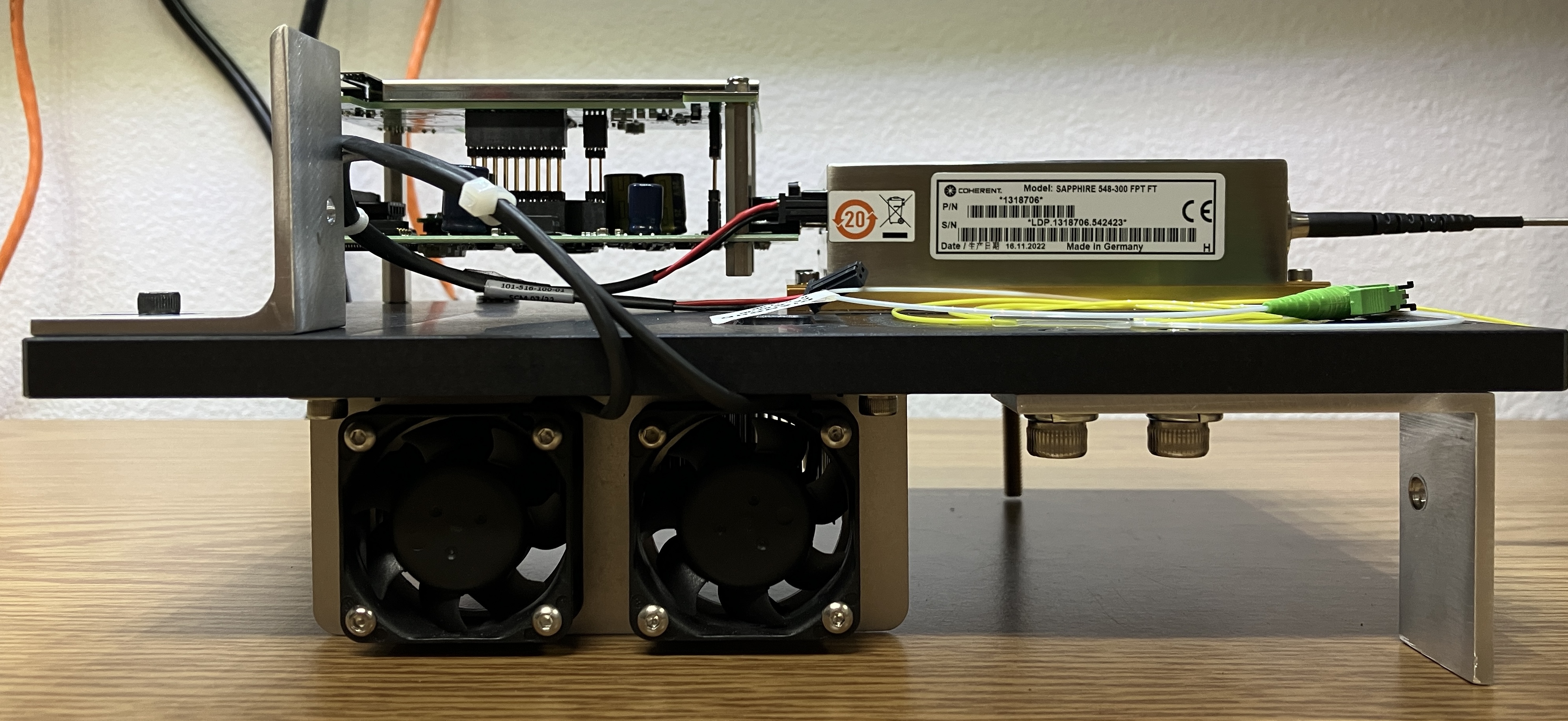
To be exact, the model identifier of this specific laser head is "Sapphire 548-300 FPT FT". The "FTP FT" portion denotes this laser as being fiber coupled instead of just producing a free space beam. There are several sub-models of the Sapphire laser system from Coherent. They include Sapphire FP, LP, LPX, and SF NX. Interestingly, this exact model and wavelength of Sapphire laser head does not show up in any datasheet or piece of documentation publicly available on Coherent's website. This is odd as the laser head was manufactured in 2022, and we are nearly certain it's a current product. The likely explanation for this is related to the uncommon wavelength of 548nm. As mentioned earlier, this laser system was originally part of a DNA sequencer, and was likely manufactured by Coherent specifically for the OEM. This also explains the confusing mismatch of part numbers. A major benefit of OPSL technology is the ability to tune the OPS chip to produce a wide range of wavelengths, including exotic ones such as 548nm. The image below shows the side of the laser head with the information sticker. The cooling fans are visible along with some modifications that we made to the base plate to ensure the unit could stand up without extra support.
The fiber pigtail is much more interesting than we originally expected. It is a single-mode "PANDA" fiber, that maintains a linear polarization throughout the length of the fiber. Laser light exits from the fiber with the same polarization angle as it originally entered with. This is an extremely specialized and high-quality fiber, designed for more than just transporting light. Refer to the article at the bottom of this page to learn more about how these types of fiber work. The "PANDA" designation refers to the internal support structure of the fiber cable. The fiber exits from the front of the laser head and is fusion-spliced to another fiber pigtail manufactured by Diamond Fiber Optic Solutions. The green piece at the end is a Diamond E-2000 fiber optic connector, which includes a spring-loaded shutter that immediately covers the output of the fiber when removed from the mating connector. When running, some stray light exits from the fusion-spliced section of the fiber and is visible, but does not seem to impact operation. Since this is a high-quality, single-mode fiber, the output can be collimated quite effectively. It is important to note that the fiber pigtail is NOT simply attached to the laser head by the 3 screws on the metal collar. The fiber continues into the sealed optical cavity and is bonded to a lens. Do not attempt to remove the fiber pigtail as you could damage the system in a way that would be extremely challenging to repair. There is a long, narrow spring that protects the fiber from strain or bends as it exits from the laser head. As with any fiber, avoid sharp bends or kinks as it could damage the delicate glass core.
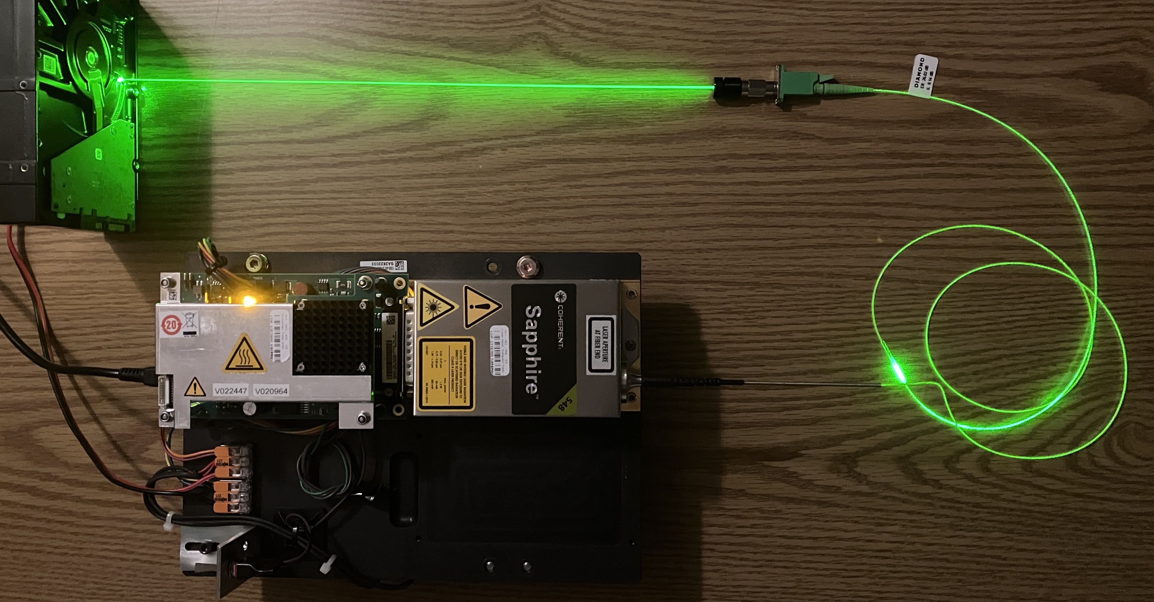
To collimate the output from the fiber into a usable beam, we purchased two components. First is an E2000-FC hybrid adapter (green and silver component pictured below). This is just an adapter that converts the Diamond E-2000 fiber connection into a more common FC fiber connection. Second is a focusable FC fiber optic collimating lens (black cylindrical component pictured below). This assembly threads on to the silver portion of the hybrid adapter, and contains an adjustable collimating lens. The fiber extends from the hybrid adapter into the lens assembly and is positioned directly behind the glass lens. The outer ring can be rotated to adjust the focus of the beam. These two components work extremely well to collimate the beam into a very fine point. They were relatively inexpensive, and links to both components will be provided at the bottom of this page. It is worth noting that it took more effort than expected to insert the E-2000 connector into the hybrid adapter, but it does securely click and lock into place. It needs to be fully inserted for the assembly to work.

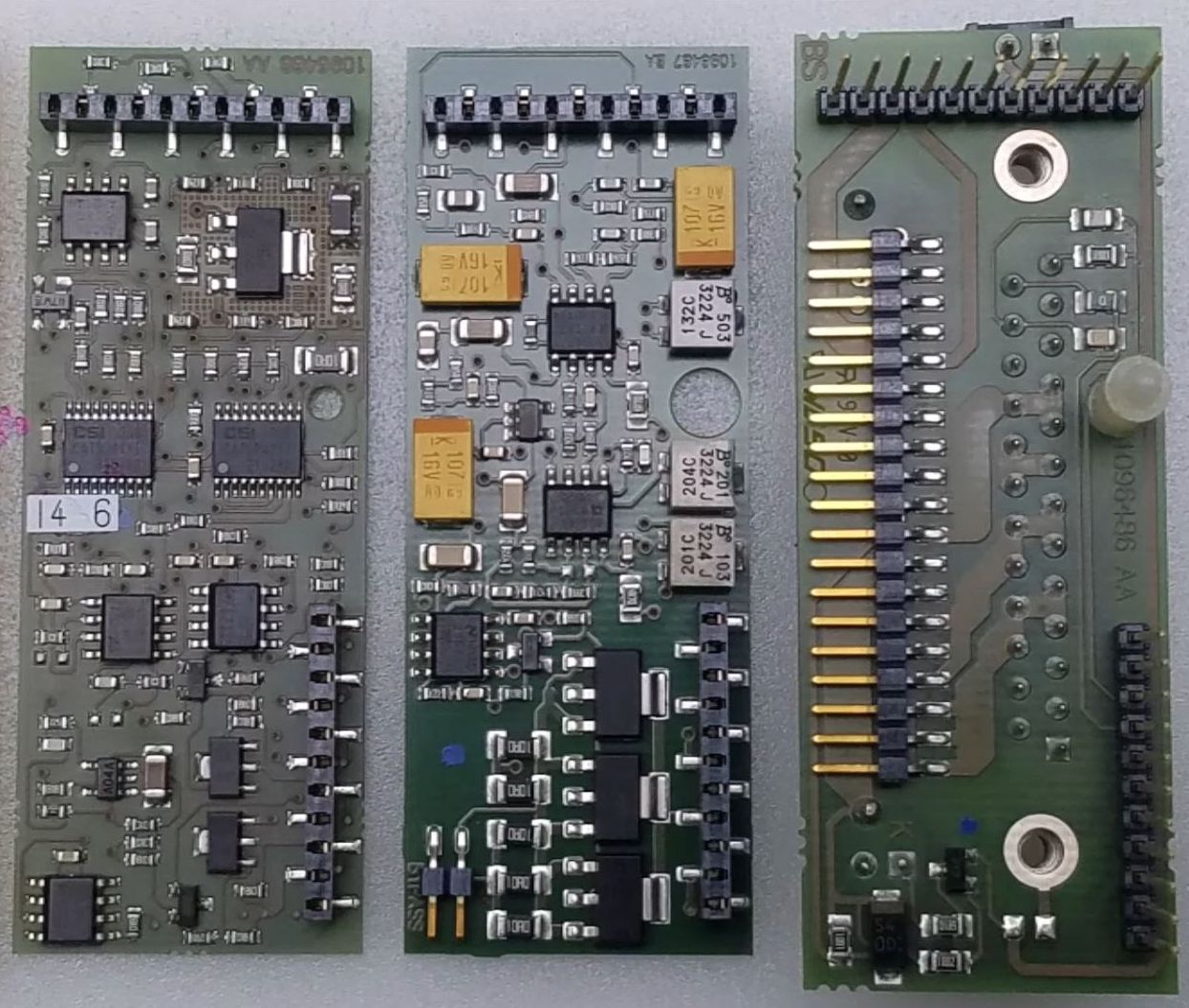
Inside the laser head is a hermetically sealed copper cover that is soldered over the ceramic optical table, which is essentially just a PCB with the optical components soldered to it. Below the sealed enclosure is the TEC that was mentioned earlier. Located directly behind the DB-25 connector (not sealed) is the "Personality Module". This is a set of internal circuit boards responsible for several functions. Firstly, they break out the connections from the DB-25 socket to the ceramic PCB within the sealed enclosure, and to the TEC. The personality module also contains an NVRAM for the storage of the head serial number, operating parameters, and more. There are a few potentiometers and a position for a bypass jumper, but their functions are not clear. Additionally, this module does seem to have a large degree of control over the internal components of the laser head. It acts as a "middle man" between the optical components and the Sapphire OEM controller. However, some components such as the TEC, seem to bypass the personality module. Since this digital module contains the information required to properly run the laser head, we suspect that it can be used with any compatible variant of the Sapphire OEM controller, but we have not tested this theory. While this does make sense to allow interchange and easy replacement of parts, it does prove to make it more challenging to adjust the head's operating parameters, or run it with a third-party/DIY driver system. The following image is of the individual circuit boards that make up the "Personality Module". They are connected together in a stacked arrangement, installed on the connector behind the sealed enclosure, and secured to the back of the cover by the DB-25 socket.
Coherent's system for driving the Sapphire laser heads is called the "Sapphire OEM controller". There are several versions of the OEM controller. The OEM Controller HP is for the higher power Sapphire laser heads, the OEM Controller LP is for the lower power laser heads. Nearly all the controllers feature an RS-232 serial interface for computer control as well as an IDC pin header for several analog I/O signals. Optionally, the controller can include a USB interface as well. There is also a fully analog controller with no USB or serial, that features an additional DB-25 connector for all the analog I/O. The controller should be matched to the power classification and model of the laser head. Further complicating the lineup, there is an LPX controller that appears to be designed specifically for the Sapphire LPX laser heads. The LPX controller has an additional daughter board mounted on top of the main board. The LPX controllers seem to omit the analog interface entirely (or at least it's not clearly defined). Coherent also provides an external solution for driving standalone Sapphire laser heads, called the Sapphire CDRH controller. The Sapphire CDRH controller is just a Sapphire OEM controller board inside of an enclosure with all of the physical controls, inputs, and outputs needed to drive the Sapphire laser head and communicate with a computer.
Responsibilities of the Sapphire OEM controller include:
-Providing regulated power to the pump diode
-Monitoring and regulating the temperature of the entire laser head, as well as sensitive optics and crystals
-Communication with the "personality module" to read head parameters and update the hour counter
-Communication with a computer or other digital equipment over the RS-232 serial (or USB) interface for control and monitoring
-Interlocks and other analog input/output signals for control and monitoring
The exact model identifier of the controller for this specific laser system is the "Sapphire OEM Controller LPT-ECL". Unfortunately, this means more confusing mismatching of part numbers, as we are pretty confident that it's an LPX controller. We would expect to see an LPX designation in the model identifier, however, that is not the case.
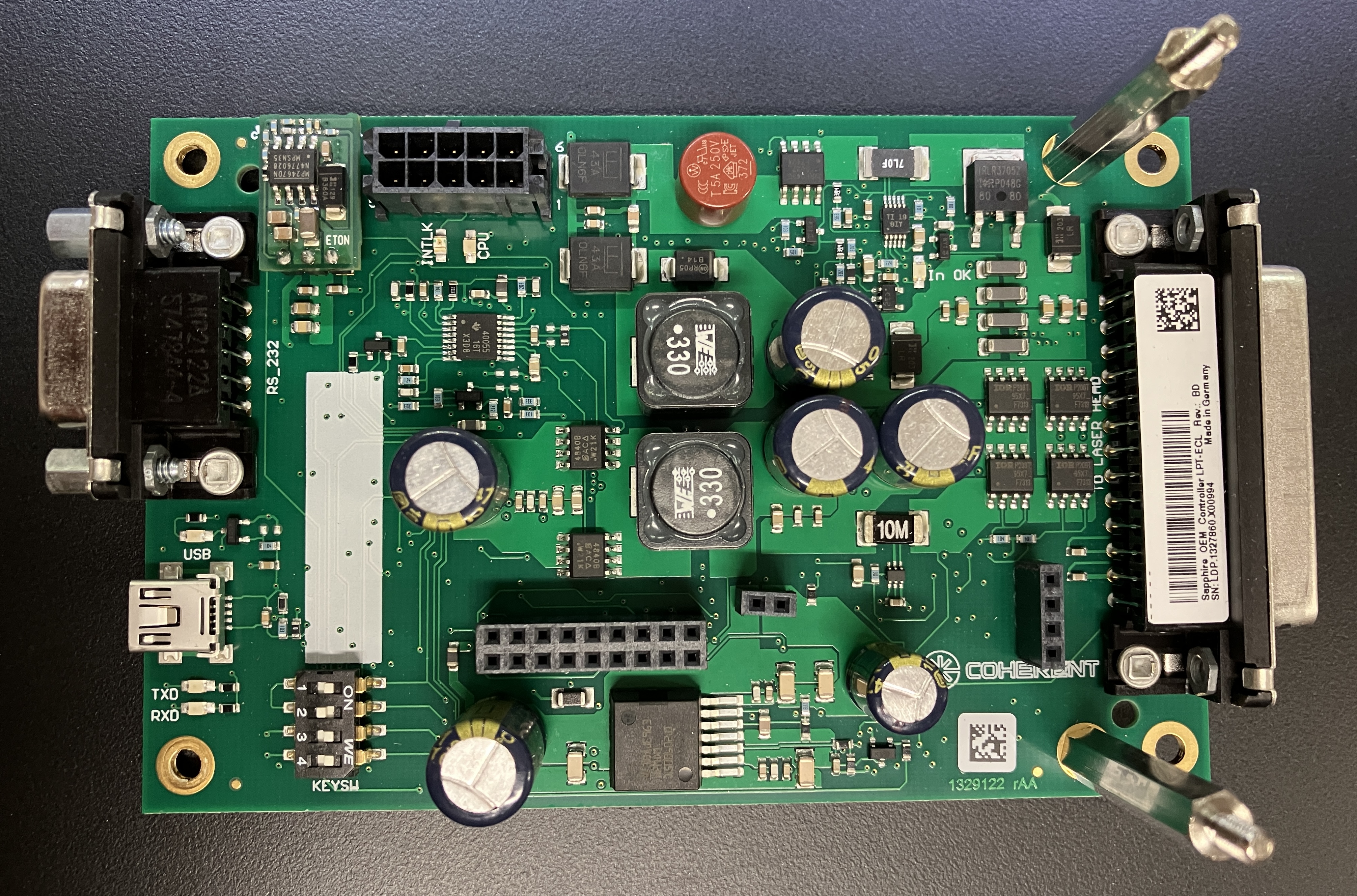
Power input and interlock signals are provided to the OEM controller through a 10-pin Molex Micro-Fit connector. The pin-out for the connector is below. Take note that pins 1-2 and 3-4 are connected together, respectively, for increased current handling capacity.
CRITICAL NOTE: The printed silkscreen numbers near the Molex connector on the LPX controller board are INCORRECT! You must refer to the Sapphire LP OEM Operator's Manual or the graphic provided below, along with the pin-out for the proper pin assignment when making connections. Failure to wire the connector properly could result in a damaged laser!
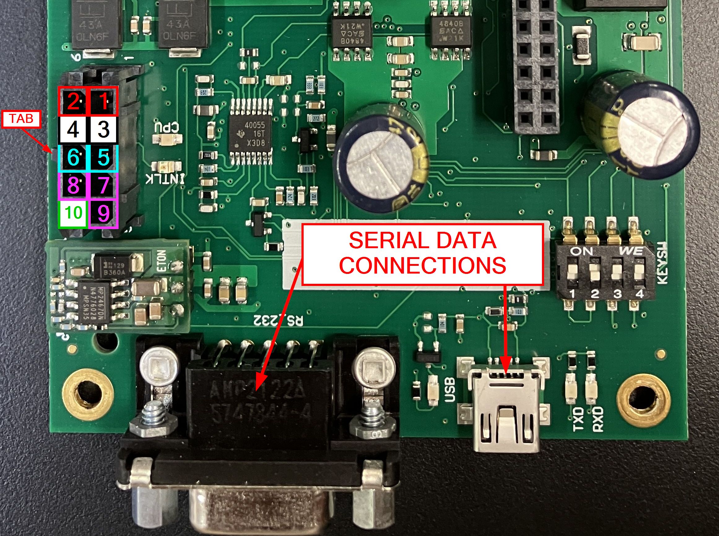
| PIN | FUNCTION |
|---|---|
| 1 | DC POWER INPUT (+10.8-15 VDC) |
| 2 | DC POWER INPUT (+10.8-15 VDC) |
| 3 | DC POWER RETURN (-) |
| 4 | DC POWER RETURN (-) |
| 5 | INTERLOCK INPUT (+) |
| 6 | INTERLOCK INPUT (-) |
| 7 | KEYSWITCH (NO) |
| 8 | KEYSWITCH (NC) |
| 9 | KEYSWITCH (COM) |
| 10 | CHASSIS GROUND |
Both the Sapphire OEM controller USB and non-USB versions also feature an analog interface. On the non-USB version, the analog interface connector is a DB-25 connector. On the USB version, the analog interface is a 26-pin IDC connector. They are functionally equivalent, but it is worth nothing that when the analog interface is active (on the USB variant), the USB interface is disabled. There are also interlock signals that run through the analog interface, but these can be bypassed with DIP switches. The analog interface appears to be absent on the Sapphire LPX controllers. All variants of Sapphire OEM controllers have a set of DIP switches that can be used to configure how the laser system operates. The interlock and key-switch signals can be bypassed and an auto-start feature can be enabled. See the table below that explains the functions of the DIP switches. Also be aware that the DIP switch package is located in different places depending on the variant of the controller. A full pin-out for the analog interface is available in the operator's manual PDF linked at the bottom of this page, but be aware that the manual linked is not for the Sapphire LPX series, so there will be some differences. Coherent would not provide us with a LPX manual.
| DIP SWITCH | FUNCTION |
|---|---|
| SW 3-1 |
INTERLOCK AT ANALOG INTERFACE (OFF = INTERLOCK REQUIRED, ON = INTERLOCK BYPASSED) |
| SW 3-2 |
INTERLOCK AT DC POWER CONNECTOR (OFF = INTERLOCK REQUIRED, ON = INTERLOCK BYPASSED) |
| SW 3-3 |
KEYSWITCH AT DC POWER CONNECTOR (OFF = KEY REQUIRED, ON = KEY BYPASSED) |
| SW 3-4 |
AUTOSTART MODE (OFF = AUTOSTART DISABLED, ON = AUTOSTART ENABLED) |
| SW 3-5 |
UNDEFINED (ALWAYS ON) *only present on OEM controller USB (not LPX controllers) |
| SW 3-6 |
UNDEFINED (ALWAYS OFF) *only present on OEM controller USB (not LPX controllers) |
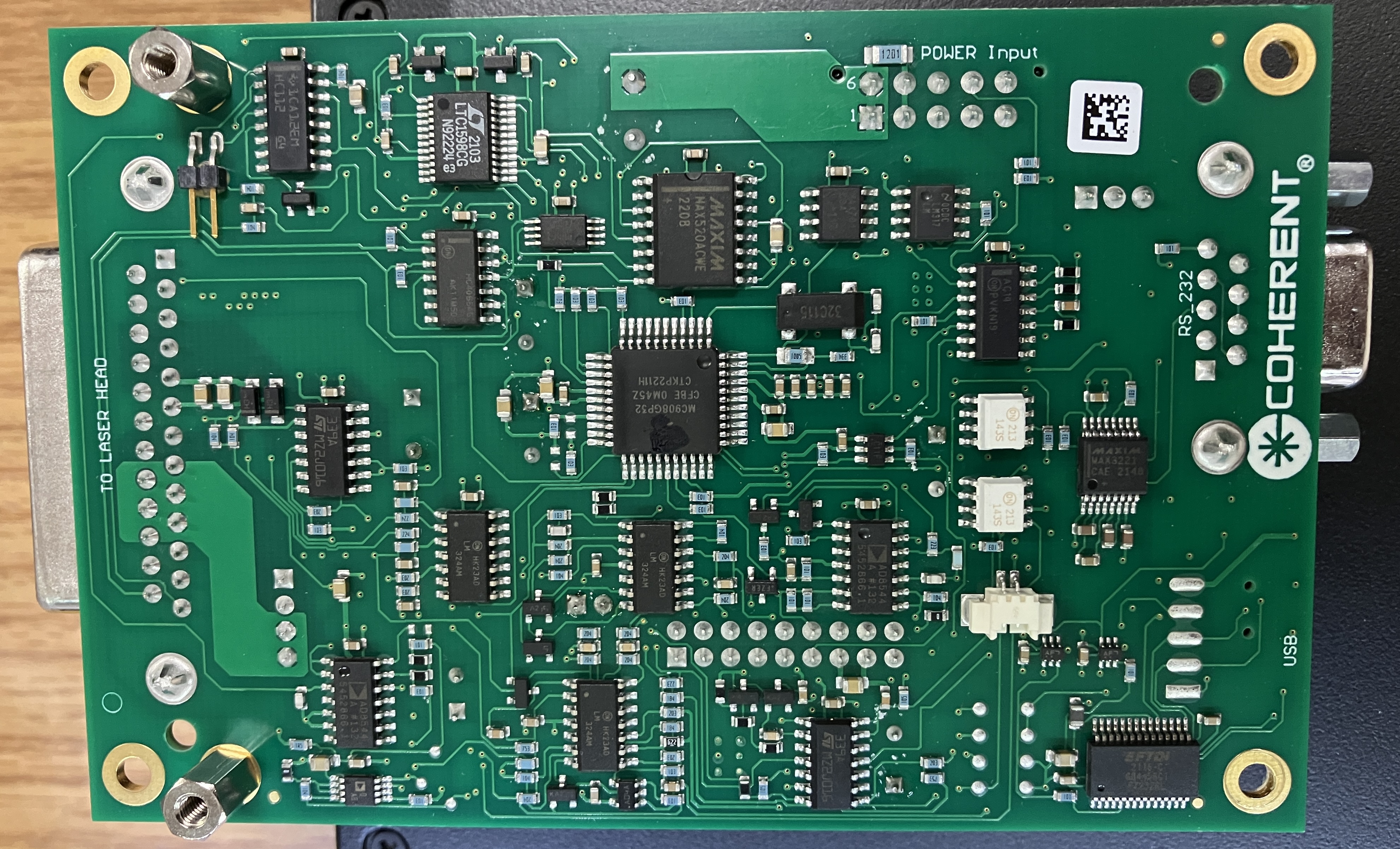
The daughter board is a rather puzzling component of this laser system. It connects to the Sapphire OEM controller by 3 different pin header connectors and is secured in place by standoffs. There is no mention of the purpose of this board in any documentation from Coherent. However, the datasheet for the Sapphire LPX does show an image of the LPX controller, which includes this daughter board. The non-LPX versions of the OEM controller (USB or analog version) do not seem to include this additional board. During our testing, we attempted to operate this laser system with the daughter board detached. The system powered on and would communicate over serial, but would not produce laser output. No errors were displayed, but the diode current reading was abnormally low despite increasing the set output power. We originally thought this board was just the OEM's system for controlling and monitoring the laser head through the analog interface. That turned out to be incorrect, this board does seem to be a Coherent part that is included with the LPX controller, and is critical to its operation. After removing the metal shield, we noticed that it has a multi-color LED on the top that flashes green as long as the system has power. We never observed any other colors or flash patterns, even when changing laser state or parameters.
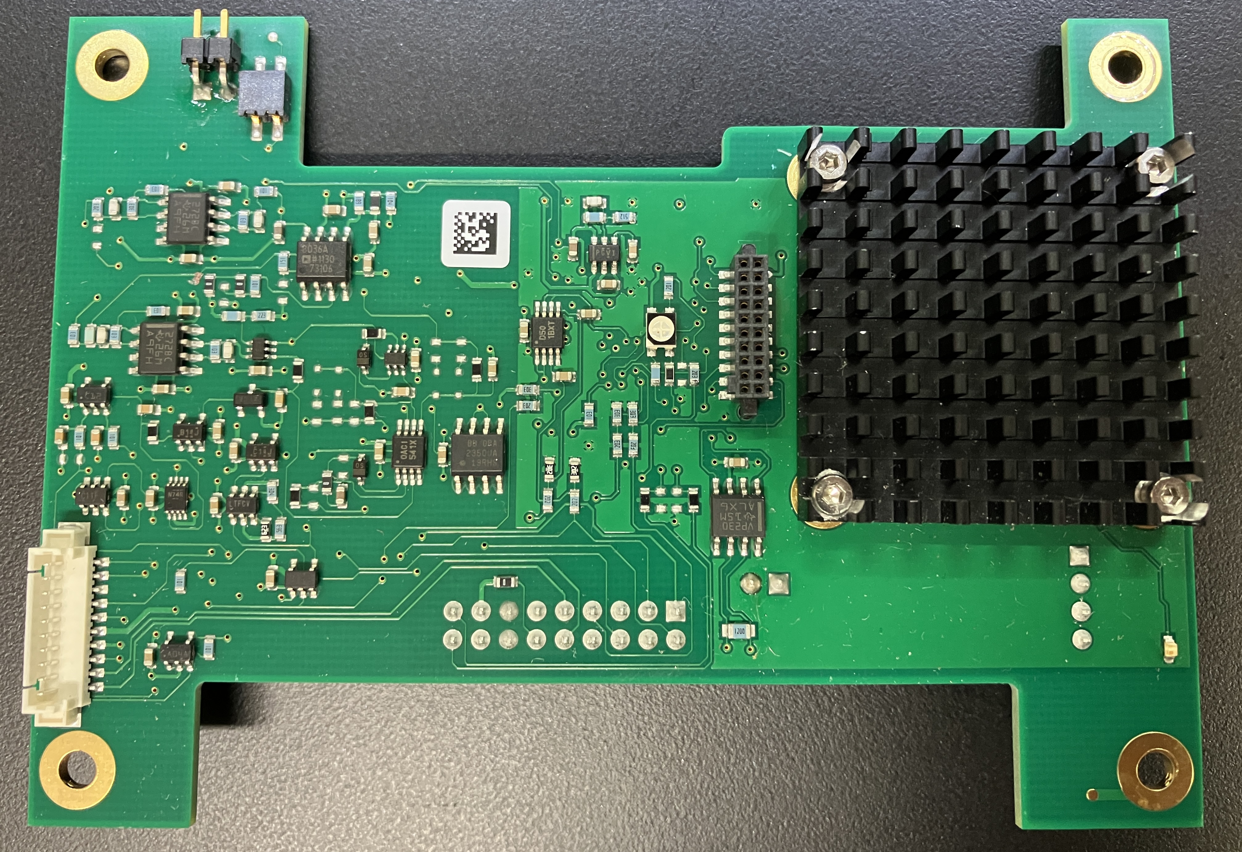
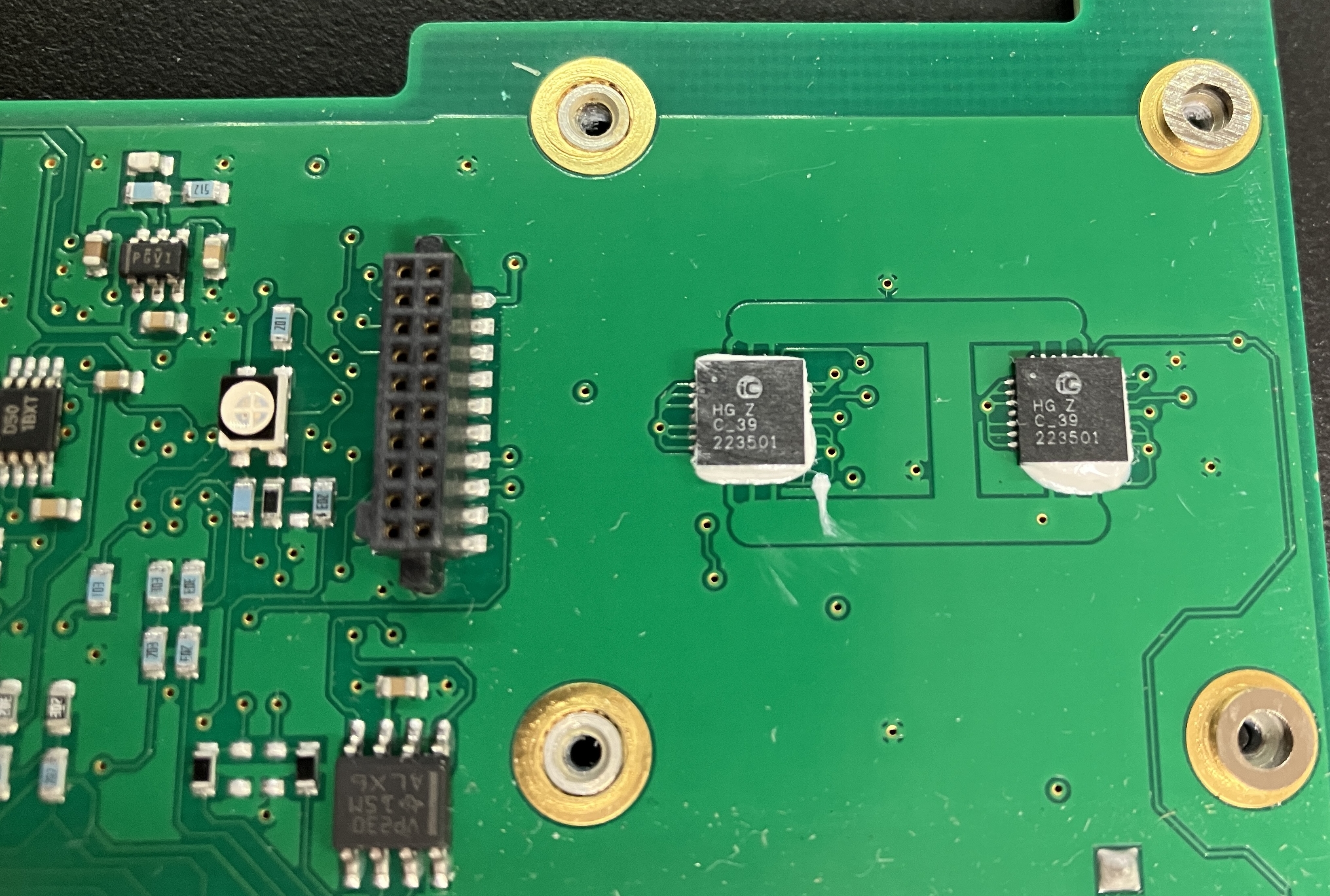
Under the small heatsink are two iC-HG 6-channel laser switch chips, which leads us to believe that this board is responsible for control over the pump diode within the laser head. As mentioned earlier, the system runs without this board, but the diode does not produce any light, and the current reading stays low. A datasheet for these chips is provided at the bottom of this page. There aren't many other noteworthy components on the top of this board other than a few unlabeled connectors. Our final conclusion for this additional board is that it's a diode driver or amplifier board specific to the higher power Sapphire LPX systems. Perhaps the higher power driver circuitry could no longer be integrated into the footprint of the original OEM controller board, thus requiring this extra board.
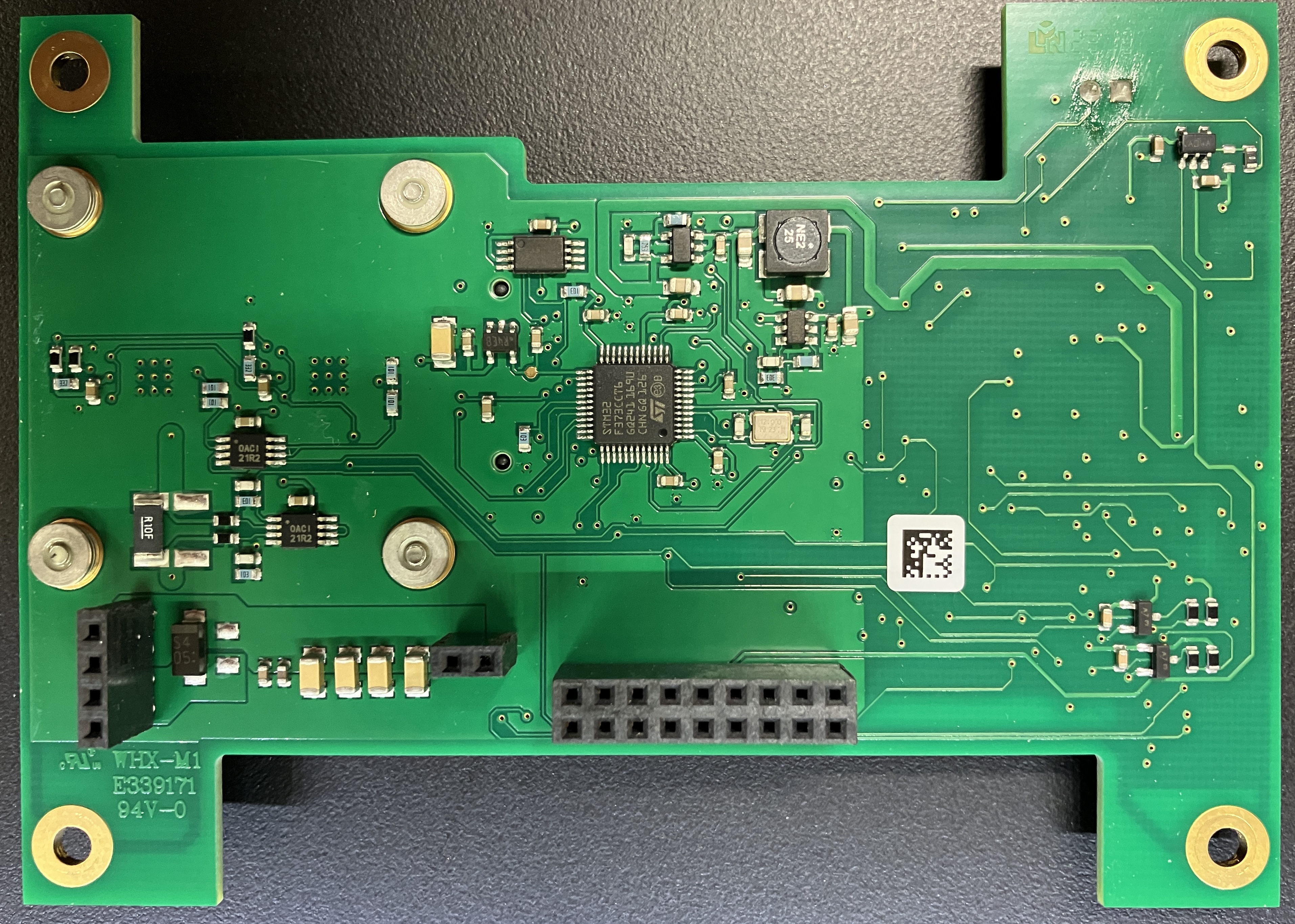
On the back of the daughter board are the three pin headers that connect to the Sapphire OEM controller mounted beneath. Near the center of the board is an STM32 32-bit Arm Cortex MCU.
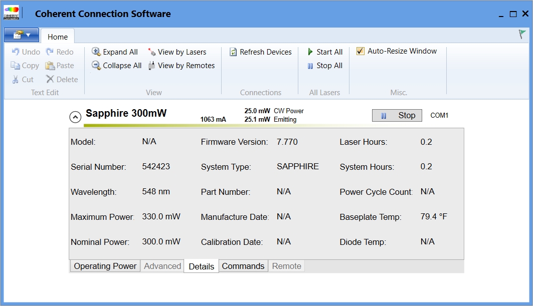
Serial communication with the Sapphire OEM controller is pretty straightforward. Connect a serial cable to the DB-9 RS-232 connector and configure a serial terminal with the following settings: baud rate: 19200, parity: none, data bits: 8, stop bits: 1, flow control: none. A USB mini-B cable can also be used to connect to the OEM controller (provided it's a USB variant). It uses an FTDI chipset, and will show up as a USB-to-serial converter under devices. The same parameters apply for the USB interface, it is functionally equivalent to the DB-9 serial port, but the two interfaces cannot be used simultaneously. A table of serial commands is available within the operator's manual linked at the bottom of this page. The command syntax is very similar to that of the CUBE series lasers from Coherent. Also, Coherent provides GUI software for control and monitoring of their laser systems. Coherent Connection version 6 is compatible with the Sapphire series of lasers and can be downloaded freely from the Coherent website. We would like to take a moment to thank Coherent for making their software available for public download and free of any licensing, not to mention it is very easy to use! It is worth noting that the Coherent connection software will seem very slow when sending commands to the laser or getting data from it. This is because of significant programmatic delays of up to 500ms that are intentionally included. Due to the design of the OEM controller, serial commands must be spaced out and not be sent too rapidly or the unit will throw an error or respond with invalid information. Even the operator's manual mentions that a 500ms delay should be included between serial commands. While this is pretty extreme, there is nothing that can be done unfortunately. When we first established serial communication with this laser, we noticed that both the head and system hour counters read zero. We figured this was just a software glitch, but it actually started to count up after several minutes of runtime. It looks like we lucked out with this unit. It has a manufacture date of 2022 and came with zero hours on the clock. As expected for a brand new laser, its performance is stellar!
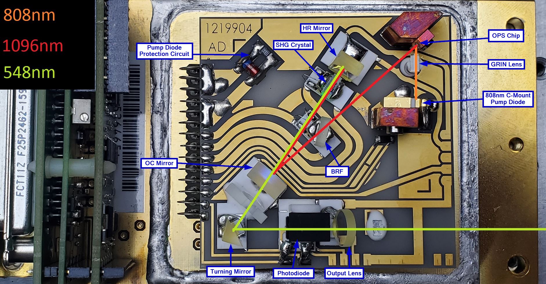
The optical path for this OPSL laser system is as follows, strap yourself in! A c-mount pump laser diode produces 808nm laser light. We estimate the max output of this c-mount diode to be between 500mW and 1500mW. Coherent's OPSL lasers are generally pretty efficient. Light then passes through a FAC (fast axis correction) lens mounted directly to the front of the pump diode. This lens makes the fast and slow axis angles the same as they exit from the diode. Next, laser light passes through a GRIN (gradient index) lens. The purpose of the GRIN lens is to condense the light down to a point on the OPS chip. Unlike typical lenses, GRIN lenses use density instead of geometry to manipulate the light. More information about GRIN lenses can be found at the bottom of this page. Light then hits the OPS (optically pumped semiconductor) chip, which converts the 808nm laser light into 1096nm laser light. Next is the BRF (birefringent filter), which filters the 1096nm laser light and narrows its bandwidth. Light then hits the HR (high reflector), passing through the SHG (second harmonic generation) crystal during the process. The 1096nm light is then reflected into the SHG crystal, which is placed between the HR and OC (output coupler). At this point, second harmonic generation takes place, resulting in the doubling of the frequency, and the wavelength being divided in half. It is important to note that the HR (high reflector) in this optical system is not only for the 548nm SHG wavelength, it is also a critical part of the OPS chip's resonant cavity. The end result is the production of 548nm laser light. The BRF and SHG crystal are mounted on small PTC heaters, and are very sensitive to temperature. Proper operation of these components depends on precise temperature control. After the 548nm laser light exits from the OC, it passes through an additional lens (purpose unknown), and then reflects off a turning mirror. After the turning mirror, some light is reflected off to a photodiode for measurement. Since this is a fiber-coupled laser, no beam forming or collimating lenses are present at the end of the optical path. The final optic is the output lens. Immediately after the output lens is a small glass pillar (damaged in picture) that the fiber would attach to. Instead of the beam just exiting from the laser head as a free space beam, it is coupled into a single-mode, unshielded fiber. This is common with OEM laser systems as the fiber allows the beam to be precisely and safely delivered to the target. Below is an annotated image of the beam path for this laser which includes labels for the optical components.
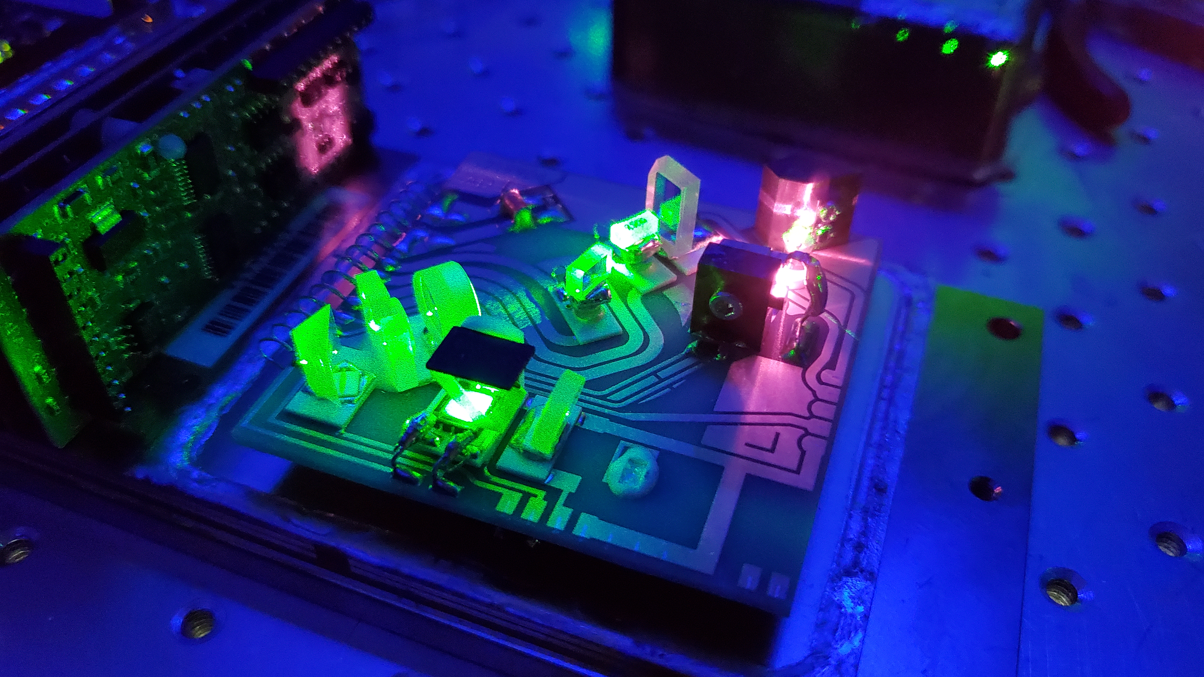
The image below was taken by Patrick (Zenodilodon) of his Sapphire 548-300 to which he removed the cover for repair. It clearly shows the IR light from the 808nm pump diode being converted to 548nm laser light. The 548nm light is a very unique shade of lime green that almost looks yellow. It is very difficult to portray the true color of laser light through images and video.
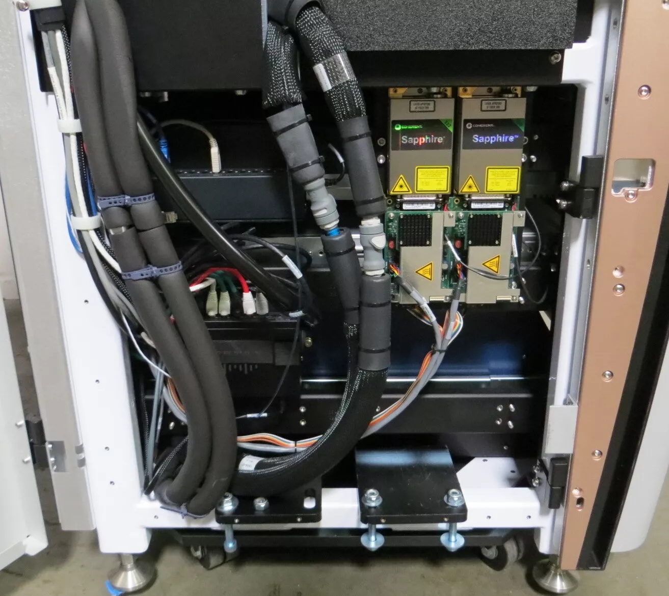
Below is an image of a Pacific Bio (PacBio) Sequel DNA sequencer (bottom half) with the side cover removed. Through some research, we were able to determine the origin of these Sapphire laser systems with a very high confidence. In the image below, you can clearly see two Coherent Sapphire laser heads with their respective controllers mounted to an aluminum base plate in exactly the same configuration as ours. This base plate is installed in the sequencer next to some coolant or fluid lines. A significant amount of Pacific Bio Sequel DNA sequencers are being parted out, and the laser assemblies are being sold separately. Notably, some units seem to contain 530nm/532nm lasers where others contain the 548nm laser heads. We are not sure what difference it makes, and not even sure why the sequencers use these uncommon wavelengths. It appears that they were manufactured by Coherent as an OEM product for Pacific Bio. This explains why this particular laser system does not show up in any Sapphire datasheets or documentation that we could find. Also, emails and phone calls to Coherent were futile, they were not interested in sharing any information about this specific laser system, other than this notable comment: "it is a special laser..."
To learn more about OPSL laser systems and their components, visit the links below. If you have a Sapphire laser head and a Sapphire driver board, the OEM operator's manual linked below will likely be very useful! Sam's laser FAQ also has useful information about repairing damaged Coherent Sapphire OPSL lasers.
- Coherent Sapphire LP OEM Operator's Manual PDF
- Coherent Connection Version 6.0 (GUI control software for Coherent lasers)
- Sam's Laser FAQ - OPSL lasers page
- Coherent - OPSL technology whitepaper
- Diamond E-2000 datasheet
- Generic eBay link for E2000-FC hybrid adapters
- Generic eBay link for FC fiber optic collimators
- Wikipedia - Polarization-maintaining optical fiber
- Wikipedia - DNA sequencing
- ThorLabs - GRIN lens application notes