This writeup is dedicated to the resonator (laser head) contained within the Laserscope/AMS Greenlight HPS surgical laser system. It's capable of producing up to 120 watts of 532nm laser light, and is pulsed/modulated by a q-switch. The pulsed nature means it can emit pulses in the kW power region. This is one intense DPSS laser! The resonator assembly is mounted to the top of the Greenlight HPS frame and is generally covered by the top plastic section which includes the display screen. The housing is made of several pieces of milled aluminum and is quite heavy.
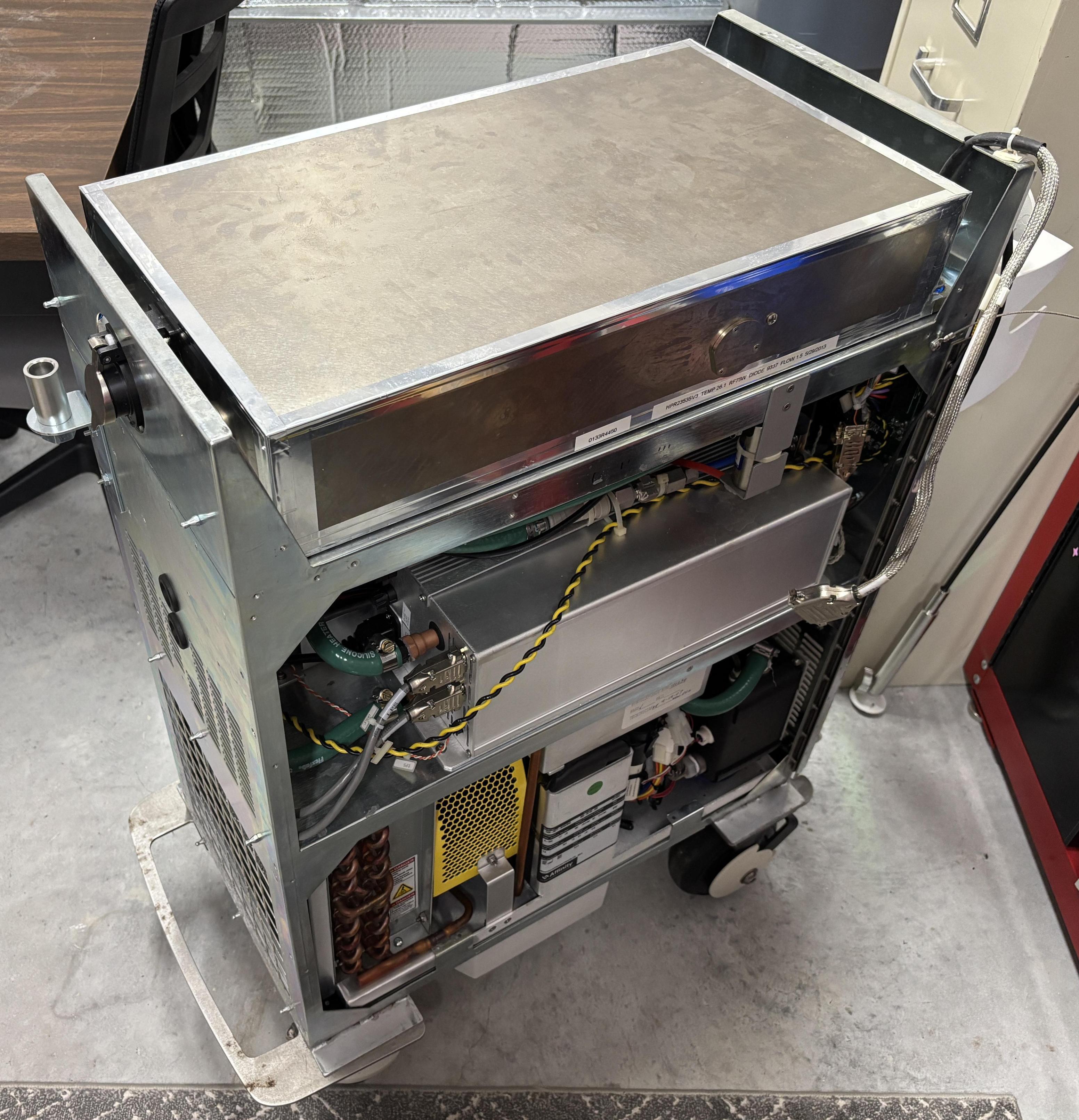
All connections except for the fiber port are located on the bottom of the resonator assembly. There are two sets of cooling water connections. The narrow blue and red tubes are for the laser diode, for which the flow is regulated by a valve below the resonator. The q-switch and YAG rod are cooled by the larger diameter hose barbs on the bottom of the resonator enclosure. High quality silicone hose is used for the water cooling connections throughout the system. Towards the top left of the image below are two studs and bolts, which are the pump diode power connections. The anode and cathode are electrically connected to the respective output studs of the laser diode driver. In a separate tray that extends below the resonator enclosure is a circuit board that is referred to as the laser control board (LCB). This board manages the crystal temperatures, monitors the photodiodes, controls the aiming beam, and controls the safety shutter. Two twist-lock connectors are installed in the tray, near the center of the unit. These are sealed passthrough connectors. The 17-pin connector carries the same CANBUS and RS-485 communication buses that are shared by the other modules. The smaller 6-pin connector is used to deliver power to the laser control board. Both the power and data connections go directly to sockets on the rear panel board. The thin black cable secured by foil tape is for the electrical contacts and thermistor within the fiber connection port. This cable goes to a connector on the rear panel board. Lastly, the three BNC connections on the middle of the bottom of the enclosure are for the q-switch crystal. The middle BNC is for a thermostat mounted to the q-switch baseplate. The left and right BNC connectors deliver RF power to each crystal individually.
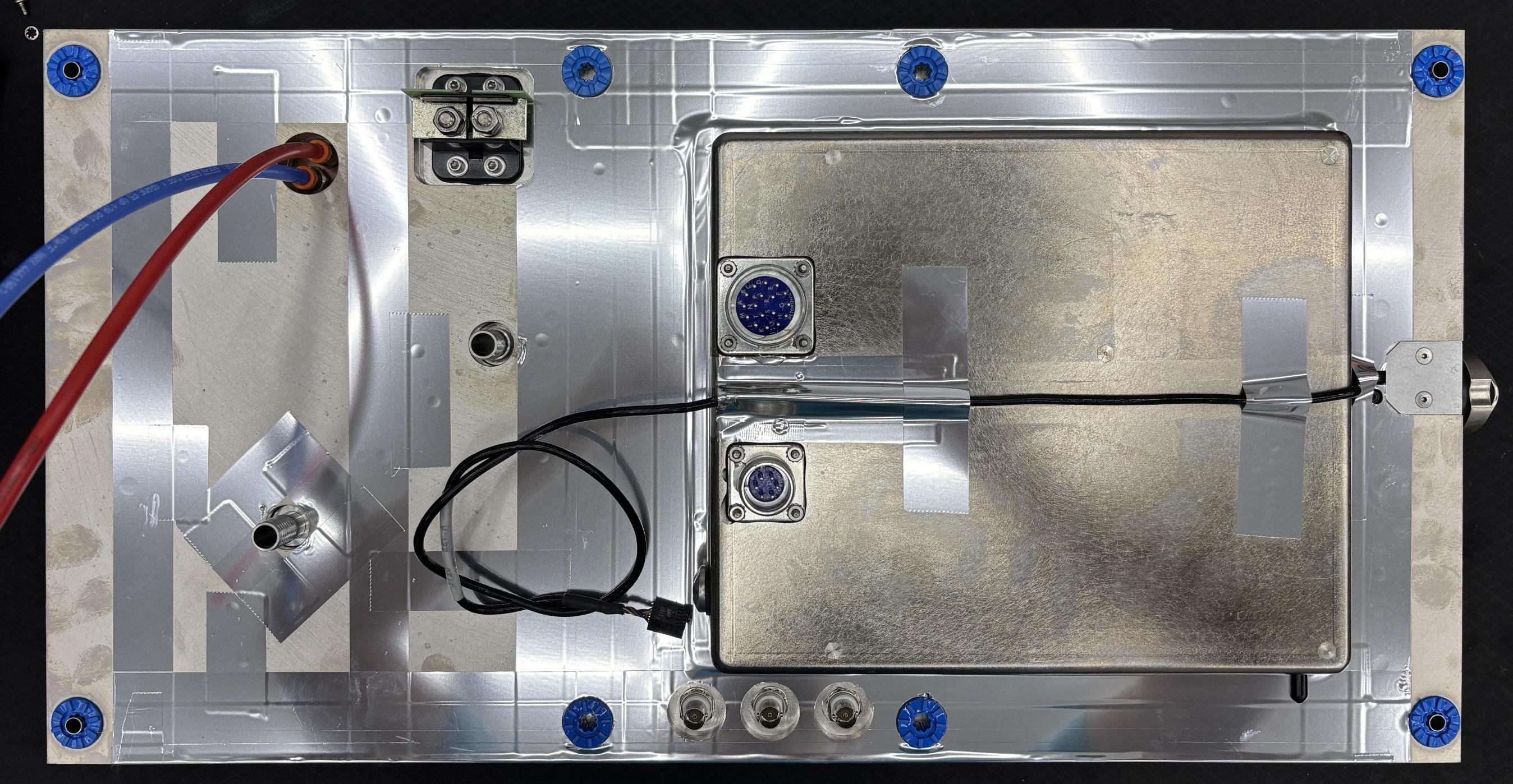
A small PCB is attached to the laser diode terminals. The board is labeled AMS Diode ESD Monitor (0133-5500) and is self explanatory. It is unlikely to fully prevent ESD, but may be used to determine if the diode has been subjected to excessive ESD.
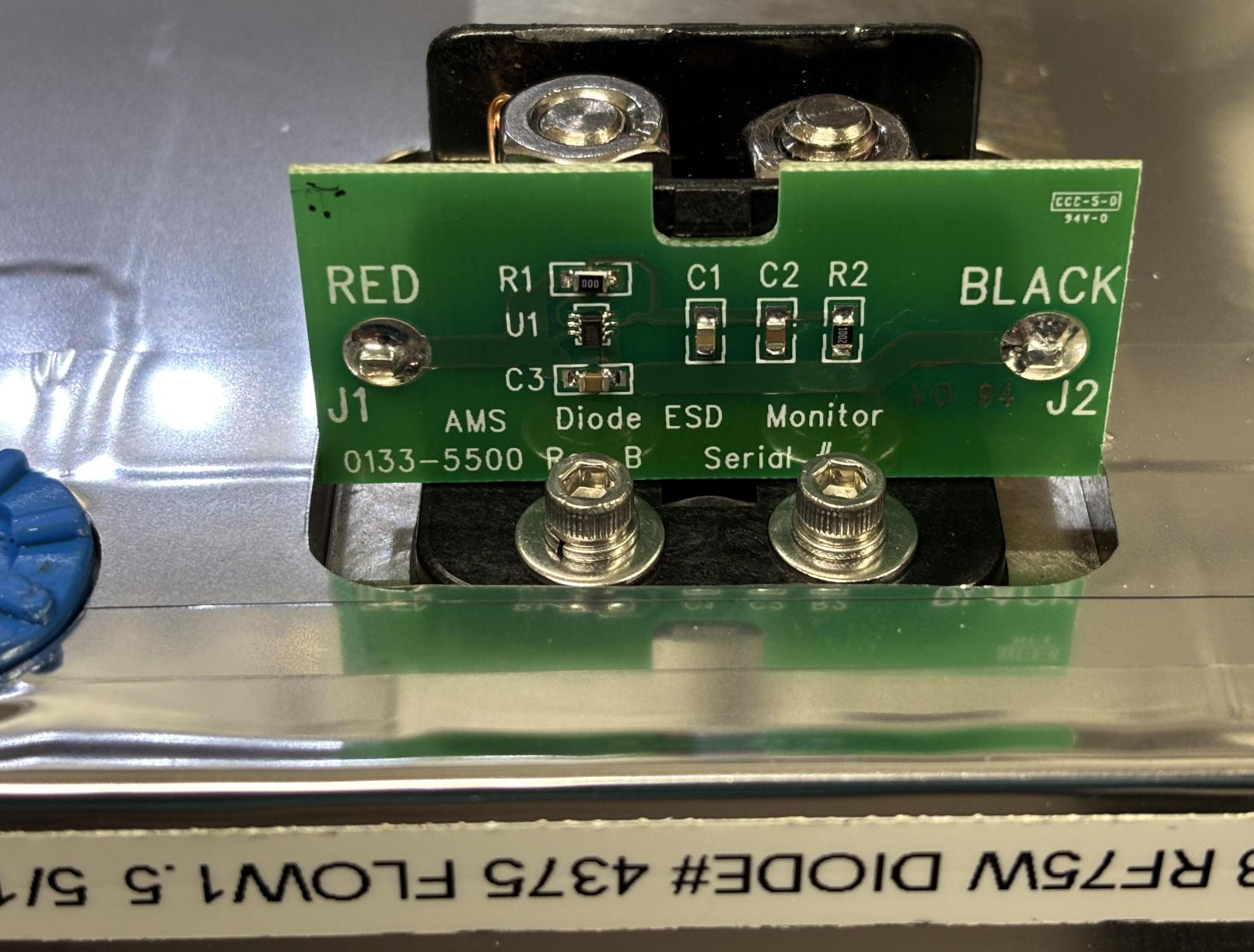
A small metal cover with a gasket allows for easy replacement of a desiccant pouch without opening the resonator and cutting the foil tape. AMS says the desiccant should be changed around every 6 months to prevent LBO coating failure.
The top cover of the resonator is secured with several hex screws. Importantly, there is no sealing gasket, only foil tape applied around the perimeter of the resonator enclosure and any openings. In order to open the resonator, the foil tape must be cut or removed. The resonator should not be left exposed to the ambient air and moisture for very long due to the hygroscopic properties of the LBO crystal coatings. They will absorb moisture over time and can be completely destroyed if the resonator is left unsealed for a while or without suitable desiccant. It is very disappointing that AMS did not use a gasket, but this is specifically mentioned in the XPS service manual, which is a very similar system to the HPS. The manual also stresses the importance of changing the desiccant every 6 months to prevent moisture buildup. This resonator enclosure is made of several individual pieces of milled aluminum. It was likely too expensive for them to design them in such as way to accept sealing gaskets. Certainly doable, but not in their best interest. The desiccant access panel does use a gasket, allowing for easy replacement of the desiccant pouch. With the cover removed, the optics are visible. It's a Z-FOLD arrangement that includes an 808nm pump diode stack, two LBO crystals for second-harmonic generation (SHG), a q-switch for modulation, an Nd:YAG rod, and a safety shutter. Other ancillary components include dual photodiodes and an aiming beam.
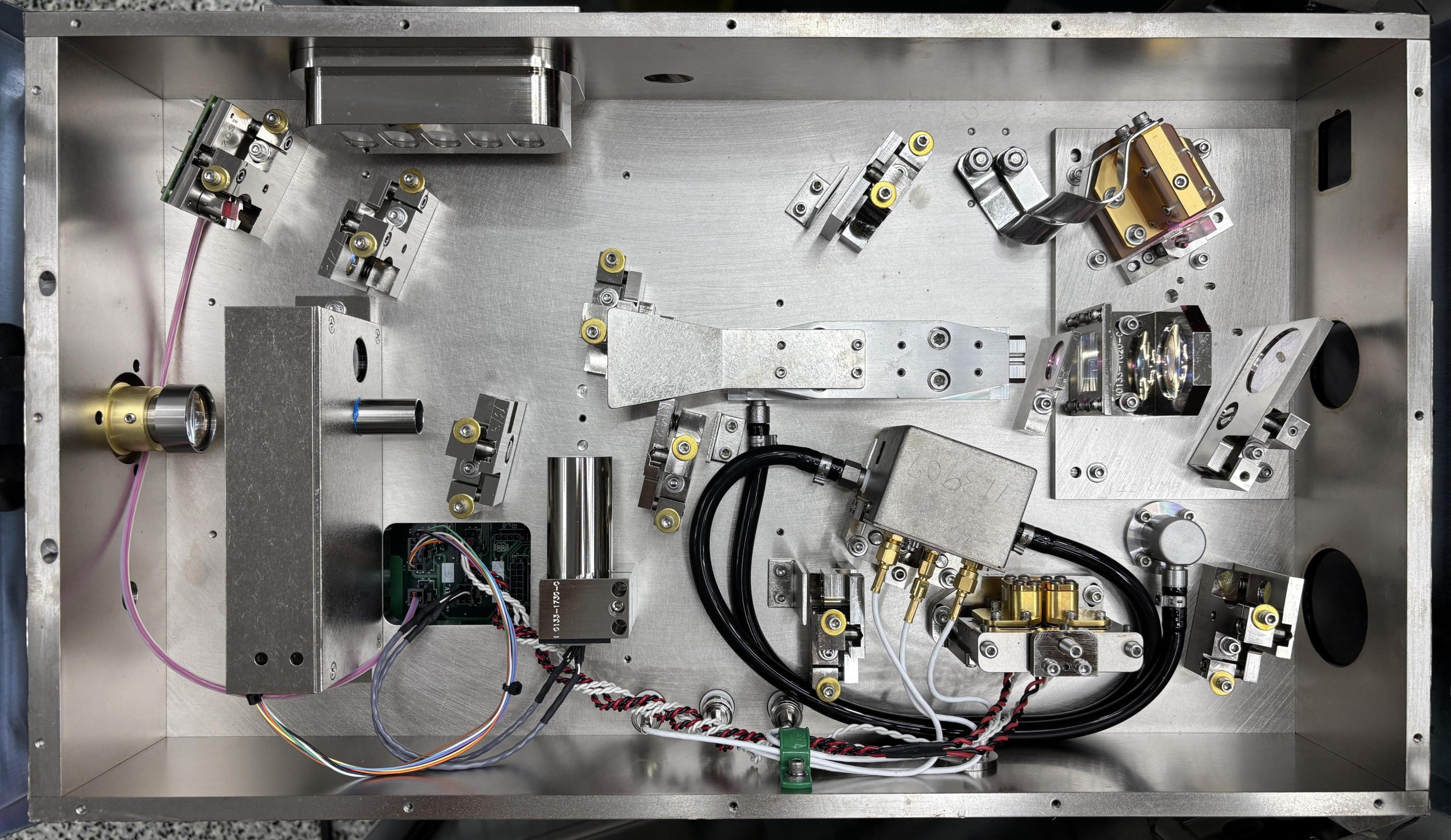
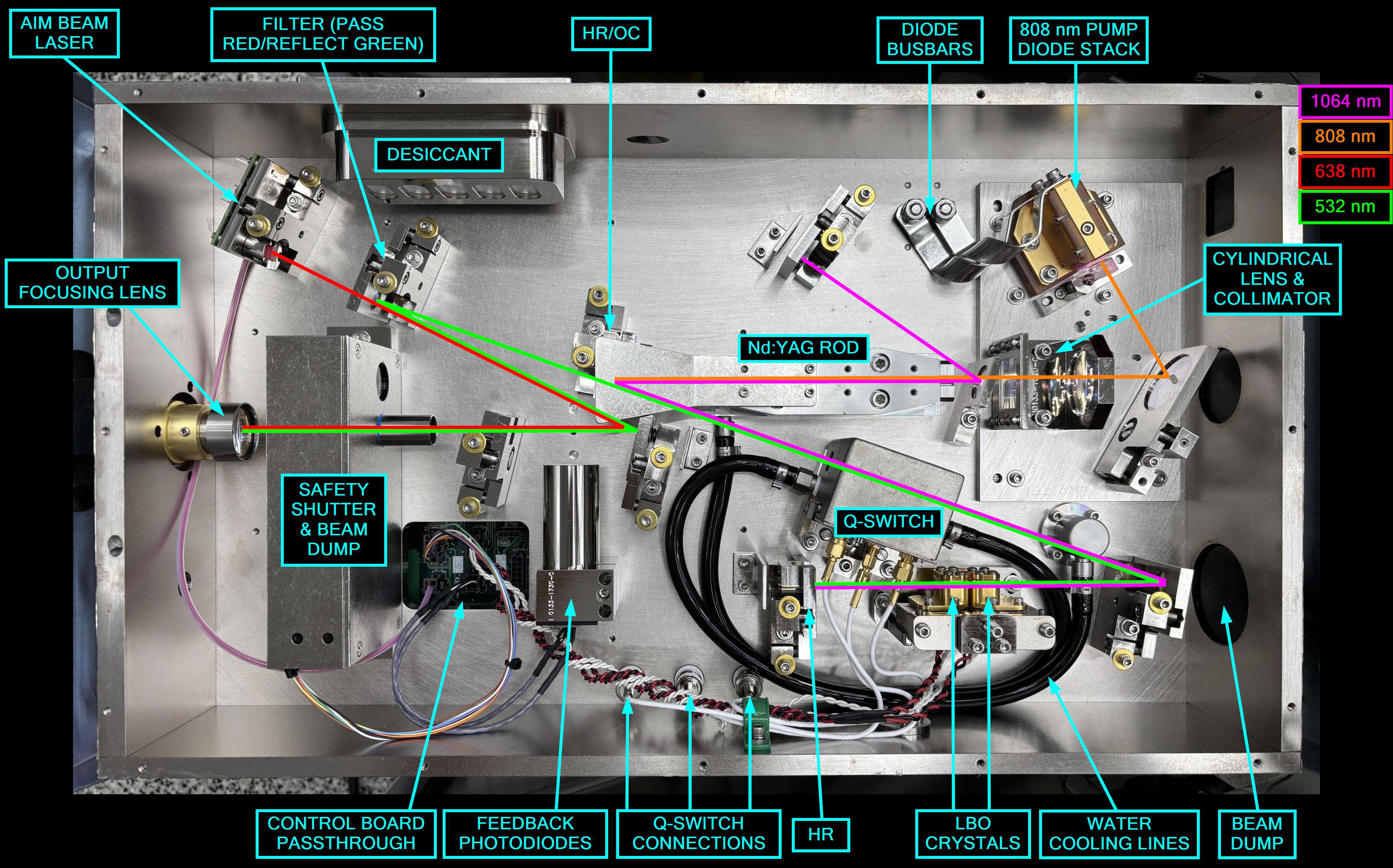
Around 200+ watts of 808nm laser light is emitted by a custom pump diode stack located in the corner of the resonator. This diode stack is water cooled due to the amount of heat it generates. Due to the high current requirements of the pump diode, solid busbars are used to connect it to a set of terminals that feed through to lugs on the bottom of the resonator. 808nm laser light bounces off a reflector and through a beam collimator and cylindrical lens which shape the beam. Light continues through an optic before entering the Nd:YAG rod from the end. A small amount of light reflects off the optic below the YAG rod and hits an optic located above. We aren't sure of the purpose of this, but there does seem to be an access port on the side of the case which would permit viewing this particular reflected beam from outside of the casing. As the 808nm light passes through the Nd:YAG rod, 1064nm light is produced due to the spectral transition of the neodymium ion. The 1064nm light then reflects off a filter and passes through the q-switch before hitting the LBO (lithium triborate) crystals. There are two crystals within the q-switch and two LBO crystals. We're not completely sure why this is, other DPSS lasers generally only include one of each. As light passes through the LBO crystals and bounces off a high reflector, SHG (second harmonic generation) takes place, which doubles the frequency and halves the wavelength, producing 532nm laser light. This exits through a filter near the YAG rod and passes through the safety shutter before hitting the focusing lens and exiting the resonator. A small 5mW aiming beam laser diode directs a 638nm beam towards a filter that passes red light and reflects green. After that, the aiming beam is reflected back towards the safety shutter and out of the resonator as well. The aiming beam helps the operator direct the 532nm surgical beam during the procedure. Below is an image that illustrates the beam path and identifies the important components.
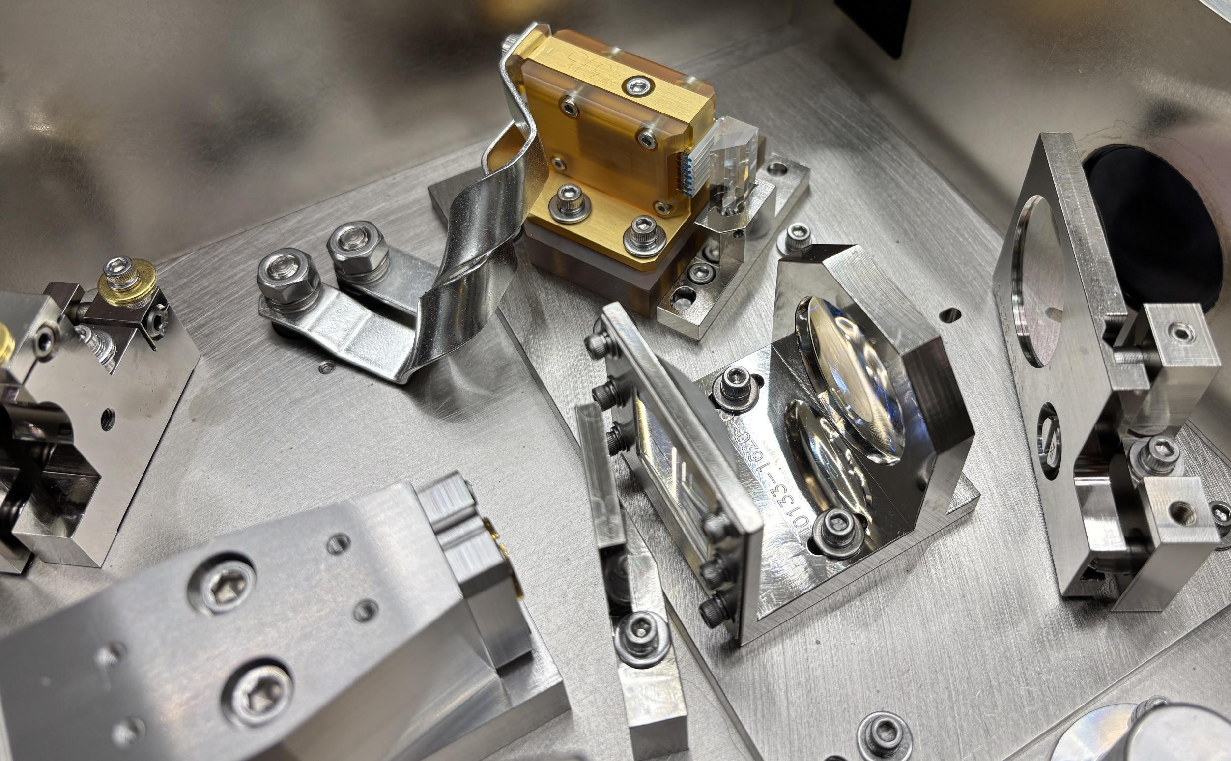
The image below provides a closer look at the monster pump diode stack. There is an array of lenses mounted directly in front of each level of the stack, perhaps GRIN lenses or similar. There is a continuous angled prism mounted in front of the stack as well.
Below is a table of diode voltage and current measurements during various stages of operation. There is very little change in voltage or current from idle to a 20 watt coag beam. It steps up a bit for the 80 watt vapor beam, but still less than we expected. The q-switch is likely doing the majority of the modulation and power adjustment work. It appears that the diode is mostly static during system operation, with only minor variations in voltage.
| STATE | CURRENT | VOLTAGE |
|---|---|---|
| IDLE | 34 A | 11.7 V |
| 20W COAG | 37 A | 11.7 V |
| 80W VAPOR | 64 A | 11.9 V |
In this image, you can see the enormous cylindrical lens which shapes the beam before it enters the end of the Nd:YAG rod visible behind it (pink coating).
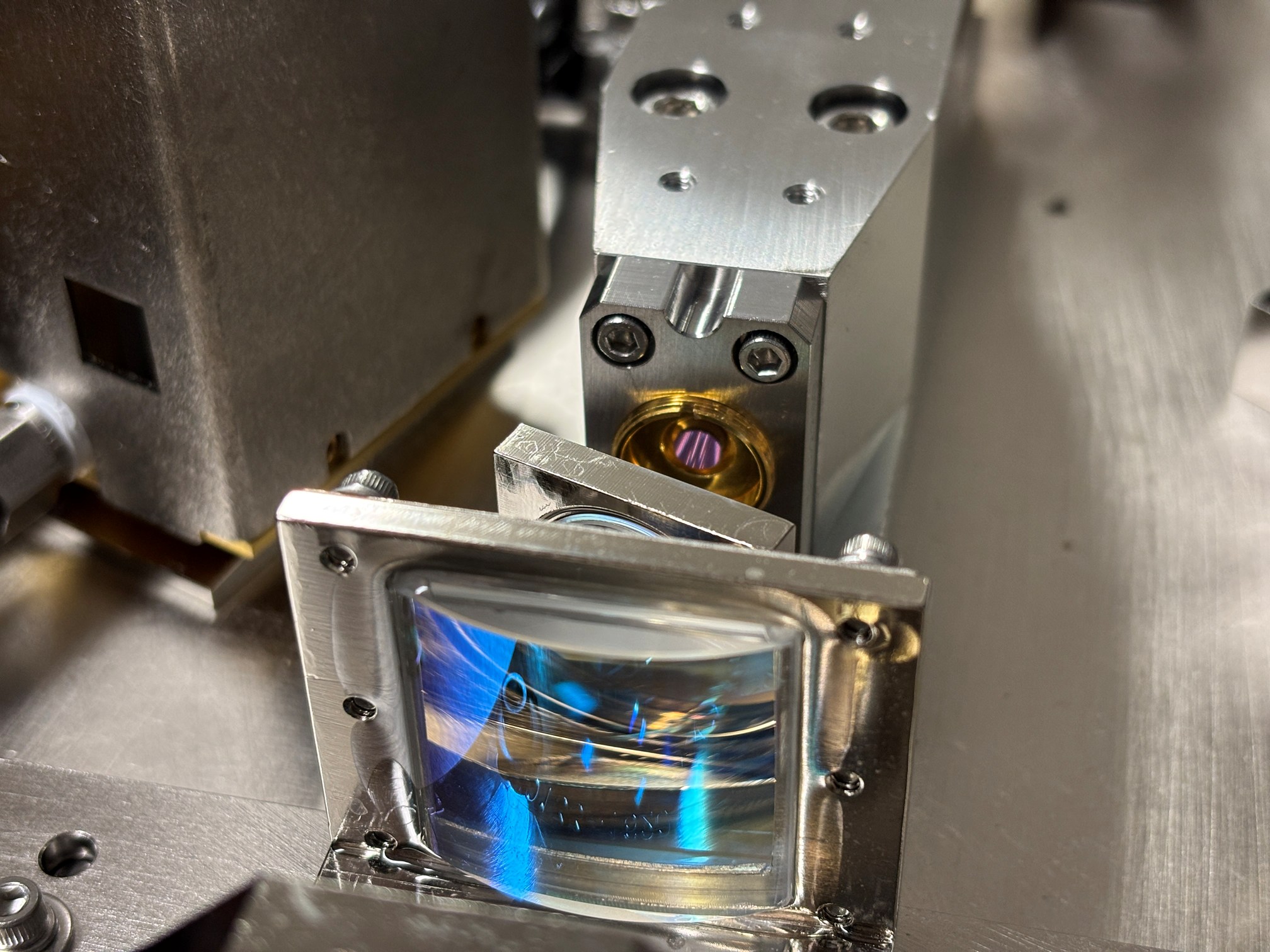
This image showcases the other side of the Nd:YAG rod and the HR/OC, the one critical component where all three wavelengths converge. All optics are secured within high quality kinematic mounts to facilitate alignment.
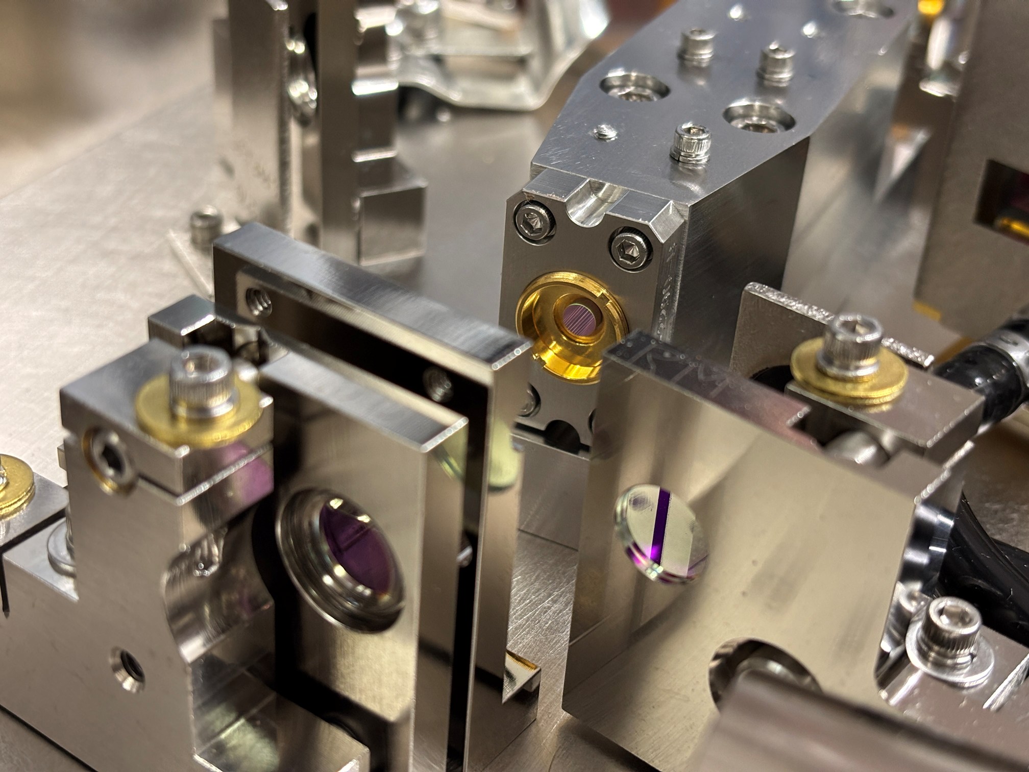
We removed the metal flange secured to the YAG rod housing in the image below, to provide a view of the HR/OC. The flange is present to contain stray beams and reflections, which protects the technician while aligning the unit. The YAG rod carrier is water cooled.
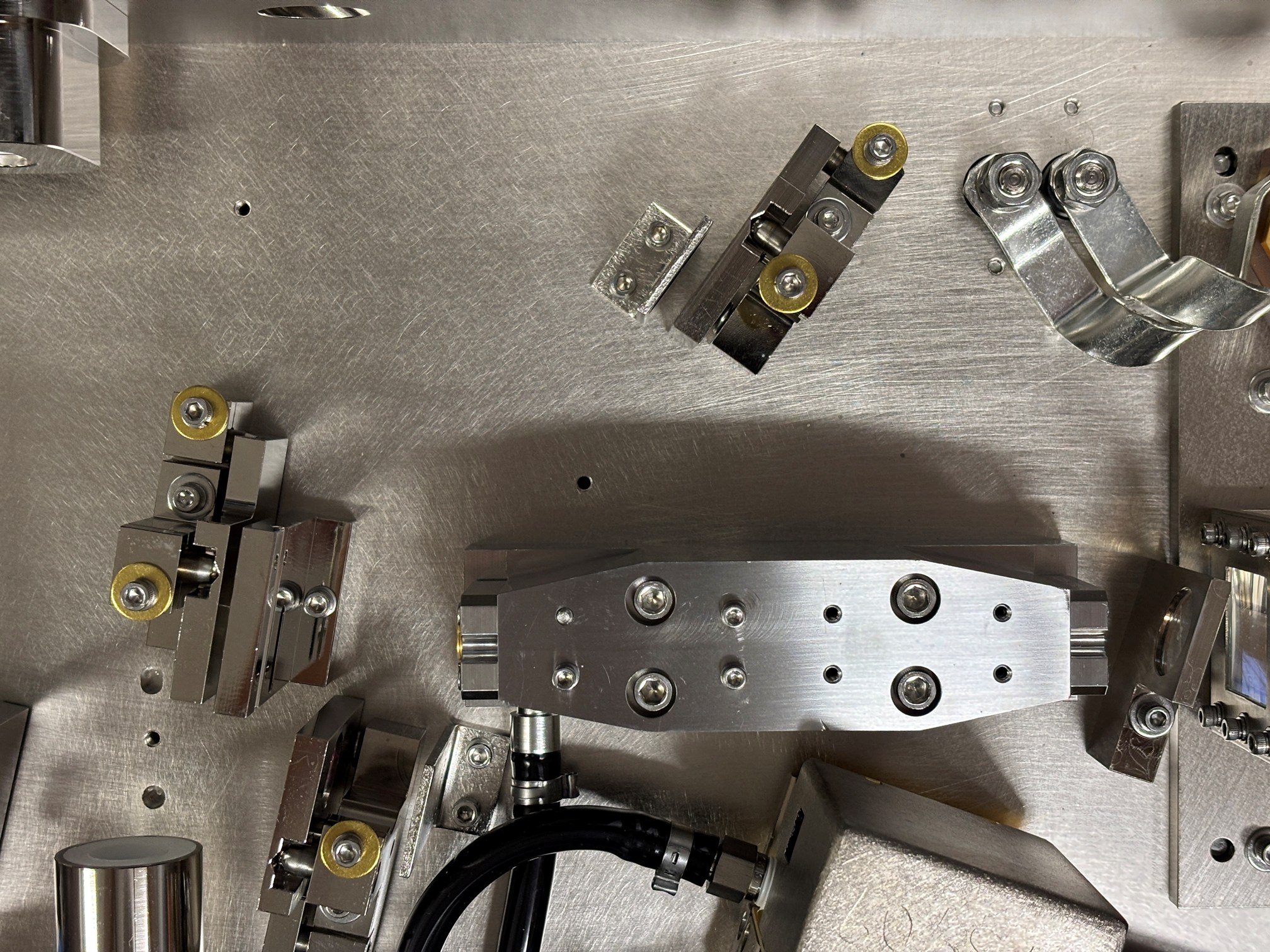
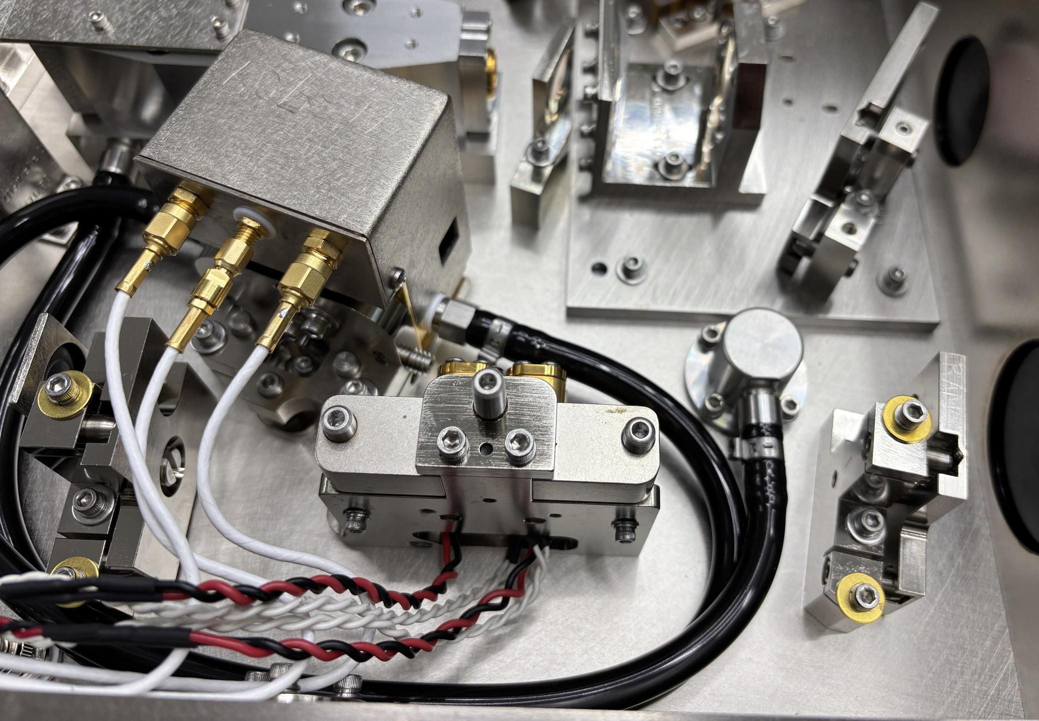
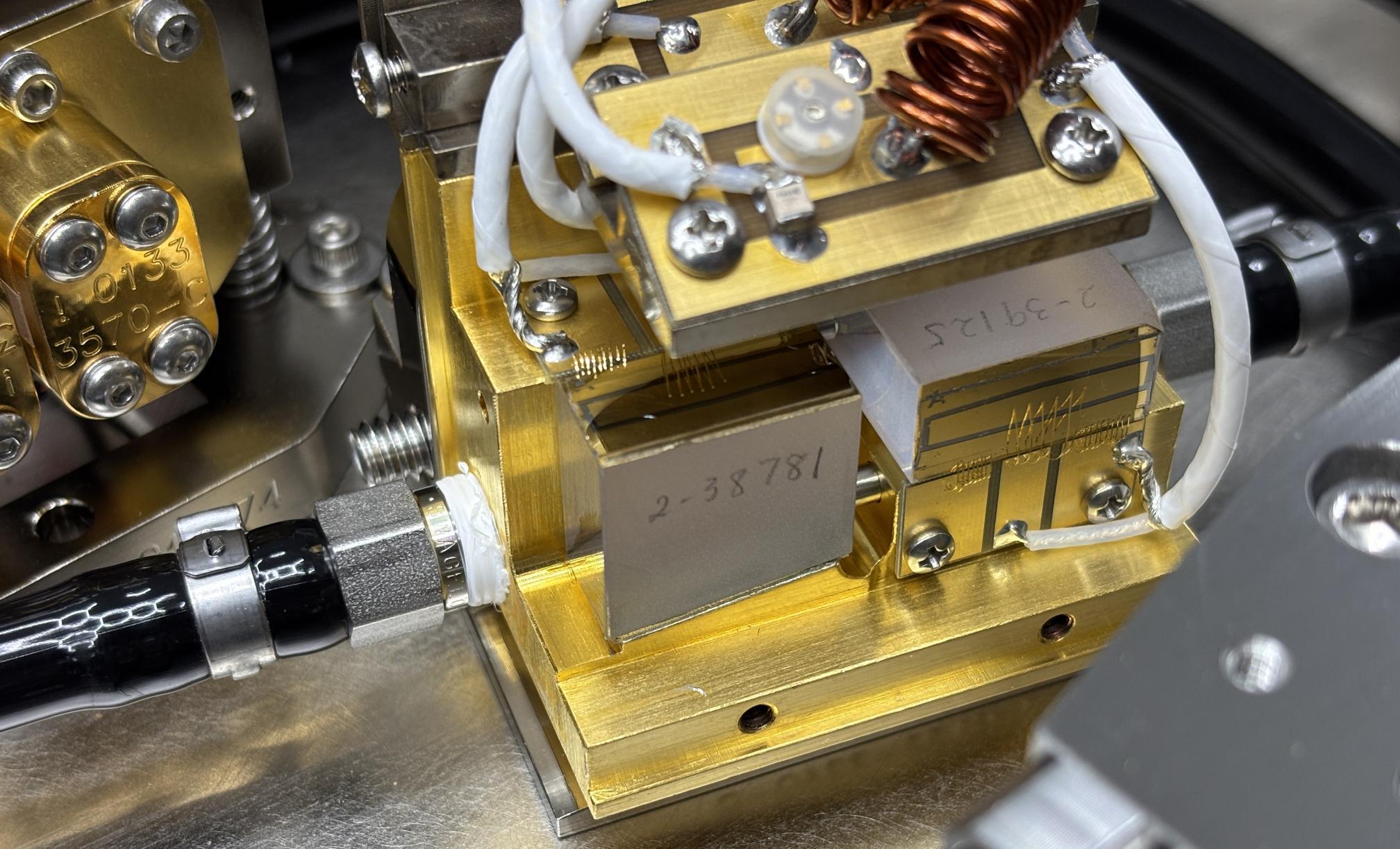
Two critical components are visible below. On the left is the q-switch crystal assembly, with three individual coaxial connections. Each crystal has a dedicated RF connection, and the center is for a thermostat. The q-switch crystal assembly is water cooled, as evident by the black hoses. To the left is the SHG crystal carrier, which includes two crystals along with their dedicated TECs and thermistors. The red and black wires route to each TEC and the white wires are for the thermistors.
This particular resonator was borrowed from a different Greenlight HPS that was already disassembled. In the image below, the effect of moisture absorption by the LBO crystals is visible. The end of the square crystal should be transparent, not frosted or opaque like the image below. Unfortunately, these crystals are damaged beyond repair and must be replaced before this system will ever produce 532nm laser light again. In extreme cases, we have even seen crystals fracture and break due to moisture. The AMS Greenlight XPS (similar system to the HPS) service manual specifically mentions the potential for the LBO crystal coatings to be destroyed by prolonged exposure to moisture. Each crystal is secured within its own platform that is independently thermally regulated and monitored from the other. They are still kept around the same temperature of 100 degrees Fahrenheit.
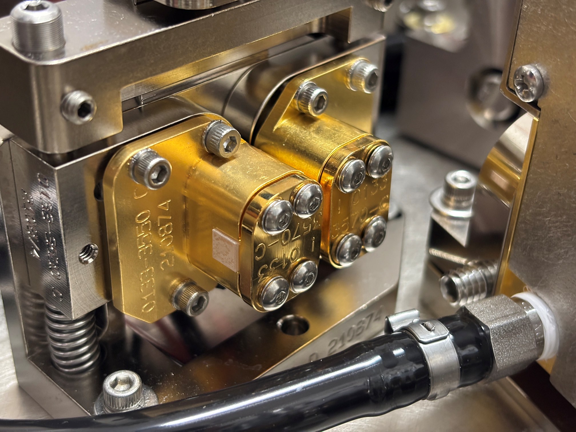
The q-switch contained within this laser head is a very unique unit. Due to the amount of energy being dumped into the crystals, the whole assembly is water cooled. Additionally, there are two independent crystals in the module, with one crystal rotated 90 degrees and placed in front of the other. It is our understanding that this was done for redundancy and capacity reasons, just to ensure the high intensity beam can be adequately modulated. We have never seen another q-switch with this dual-crystal arrangement. Each crystal has its own independent coax and RF connection. However, these combine at the BNC output connection on the RF driver. Both crystals are driven together, and cannot be controlled independently. A thermostat is installed within the q-switch crystal carrier to inform the rear panel board if the temperature exceeds the maximum threshold.
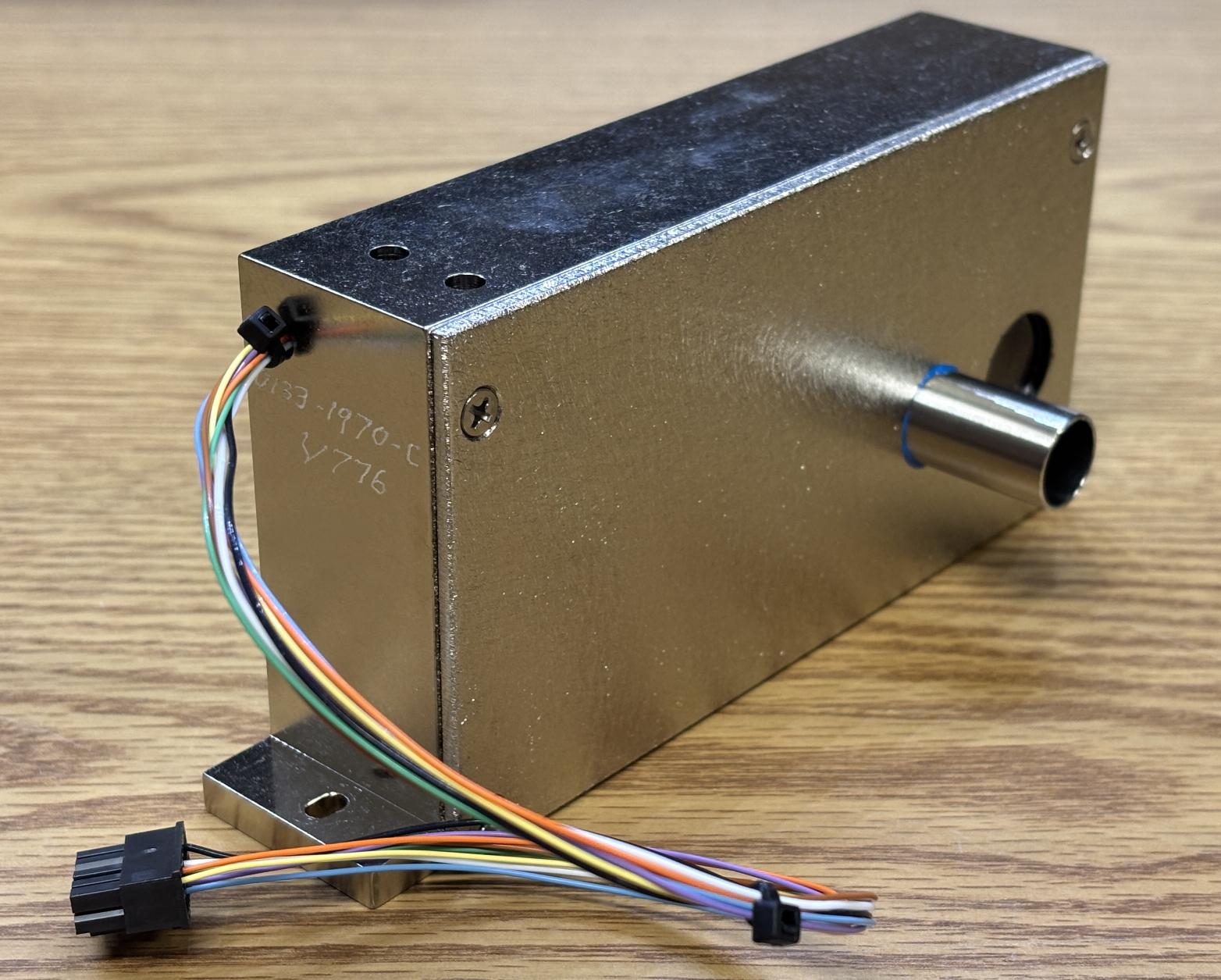
This is the Greenlight HPS resonator safety shutter. It's an electromagnetic, intrinsically-safe unit that seems to be designed specifically for this application. The shutter is driven and monitored by logic on the laser control board. Laser light enters through a metal tube on the front of the shutter and exits through a hole on the other side when the shutter is opened.
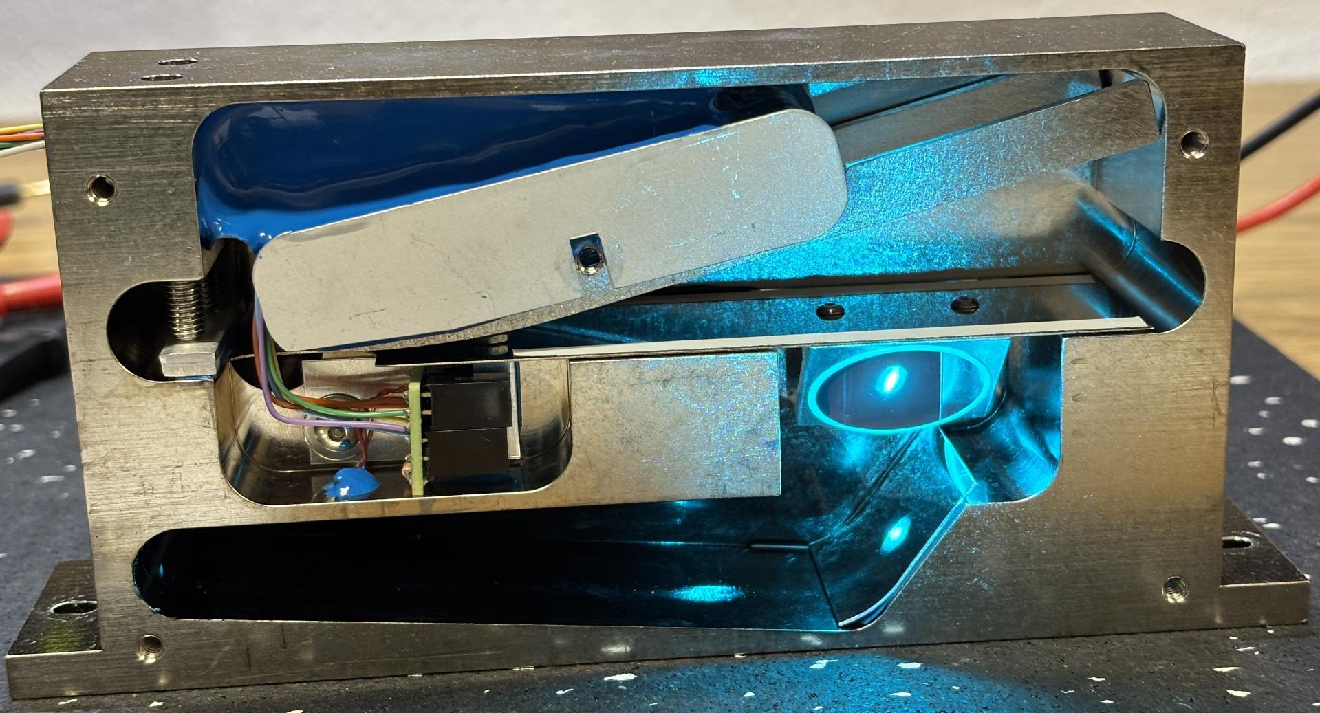
The shutter is fail-safe, meaning the default, unpowered position is closed, which blocks the beam. Using a strong 24V electromagnet, a flexible metal armature can be pulled upwards to allow light to pass, or forced downwards to block light. When unpowered, the armature springs downwards and blocks the beam. The armature moves a mirror into the beam path when it's in the closed position. This redirects the beam into the lower cavity of the shutter which acts as a beam dump. Two optical sensors monitor the position of the armature. One is normally open, and the other is normally closed. This allows the system to detect the failure of a sensor, as they should never be in agreement. The laser control board uses these sensors to constantly monitor the position of the shutter, as their states reverse when the shutter position changes. If the shutter behaves unexpectedly, the system will alarm and cut power to the diode stack. The emitters of these sensors are provided with 5V DC and then monitored by the LCB. The shutter also has an NTC thermistor adhered to the frame, which is monitored by the LCB. In the image below, a low-power 488nm beam was directed at the armature mirror to show how the beam is dumped into the lower cavity.
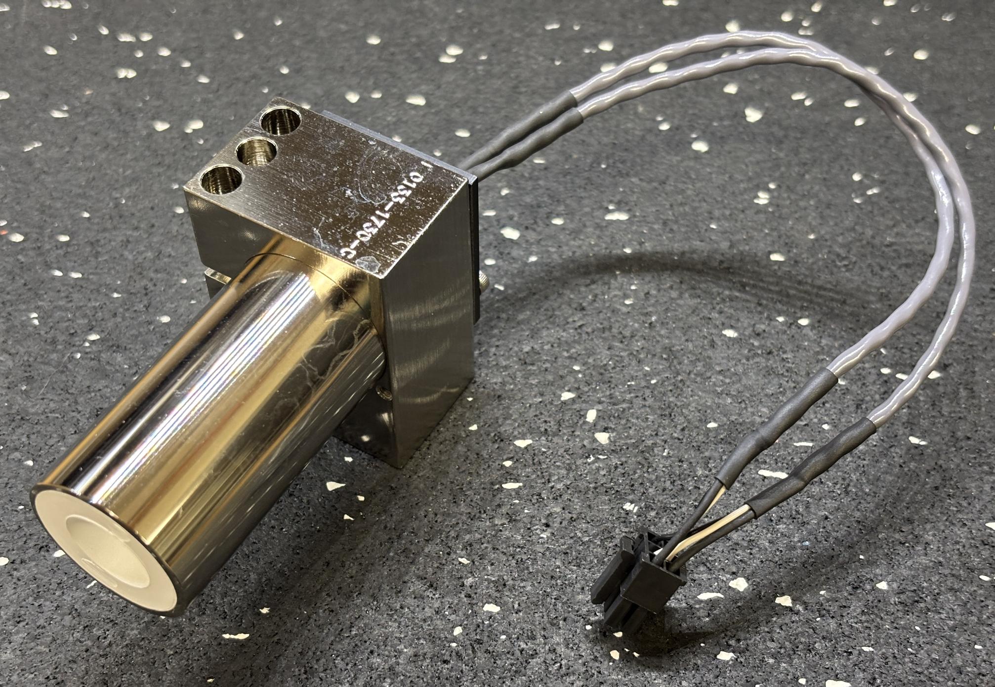
Two silicon photodiodes are installed at the end of a metallic tube with a white plastic inner structure. These photodiodes monitor the beam, but we are not surer how precisely they are able to measure the power level. The photodiode harness connects to the laser control board.
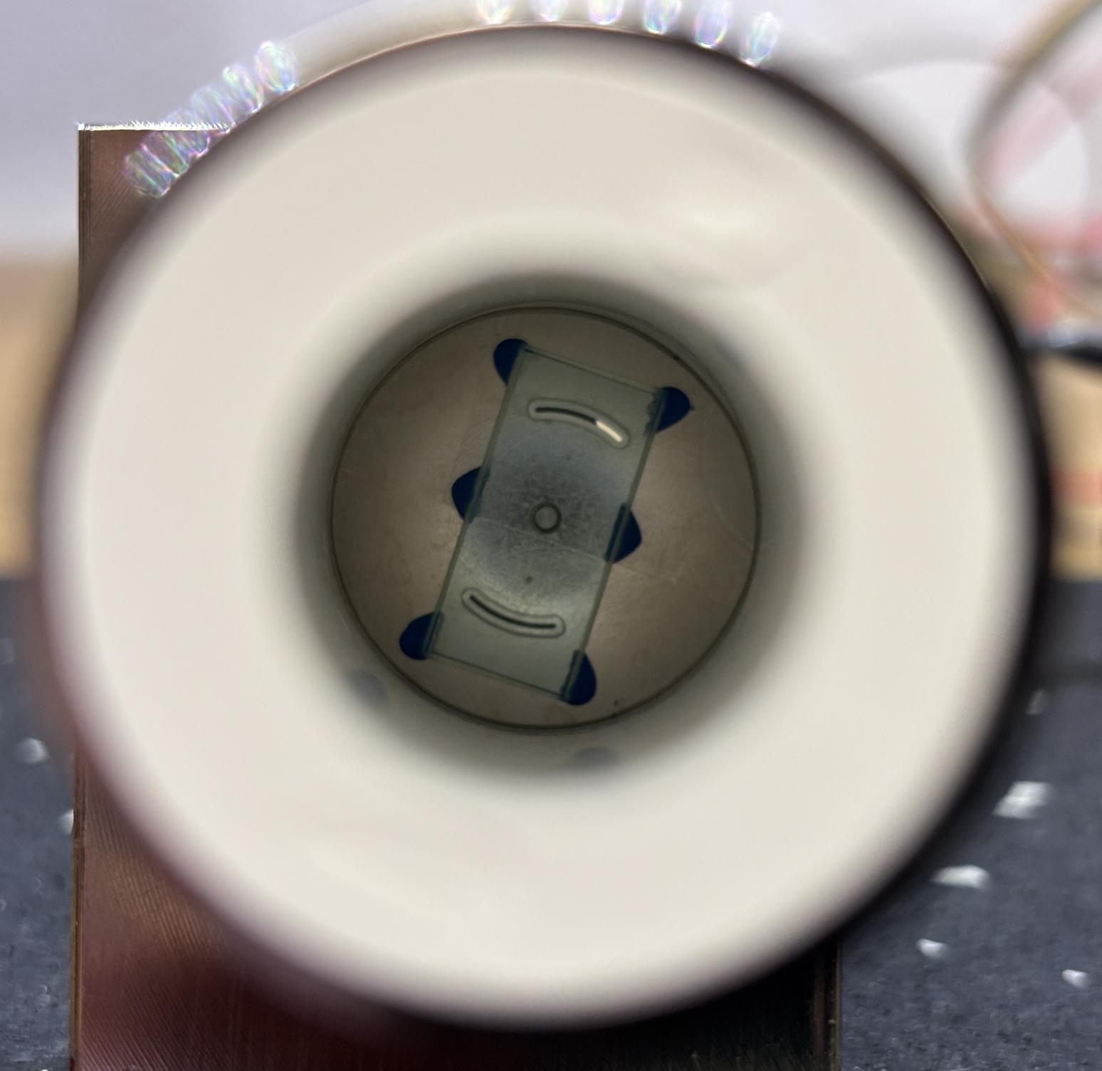
Looking down the barrel of the photodiode assembly reveals an small plate with slits cut in front of each photodiode, perhaps to limit the amount of light that can pass through.
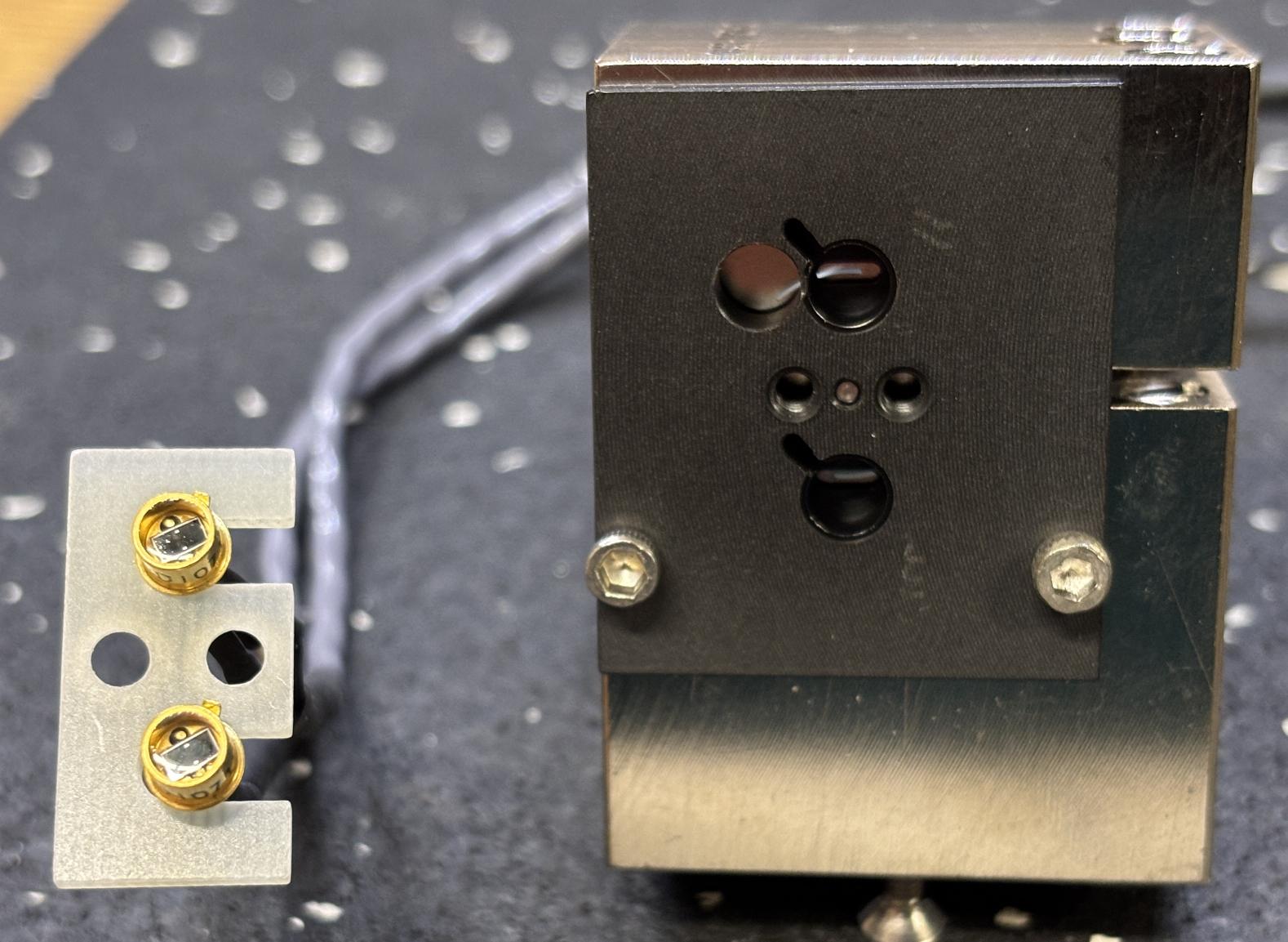
A milled section of PCB keeps the photodiodes held into the rear of the assembly. Both photodiodes are PIN-3CDI models manufactured by OSI Optoelectronics.
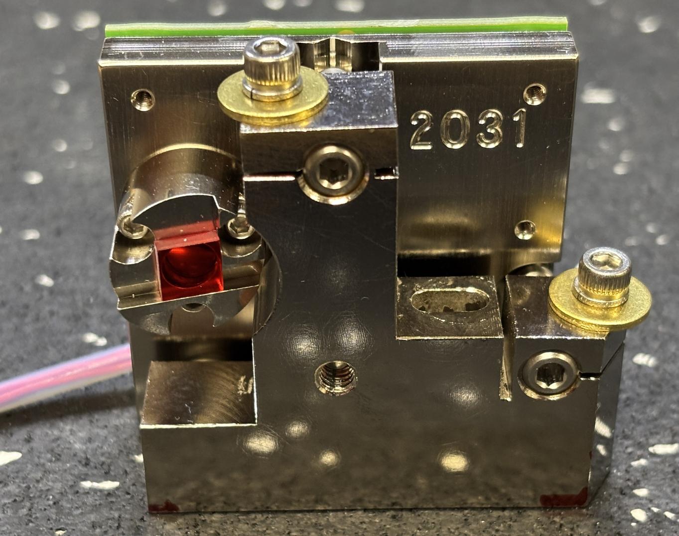
This is the aim beam module. It incorporates a 5mW 638nm red diode laser and small driver board onto a kinematic mount, which secures to the baseplate.
The board is labeled AMS AIM REV B. The board receives 5V DC, a ground connection, and a control connection from the laser control board. 3 of the 4 pins on the Molex Micro-Fit connector are utilized. The 4-pin white header is likely used for calibration or testing and is left unconnected inside of the resonator.
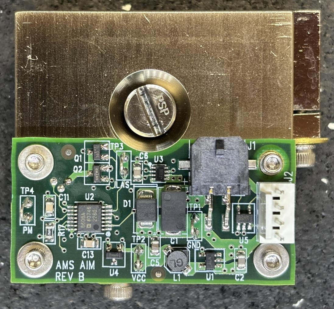
To enable the aim beam, connect 5V DC to pin 1, GND to pin 3 and use pin 2 as the control/enable signal. Voltage can be varied from 0-5V on pin 2 to adjust the intensity of the aim beam.
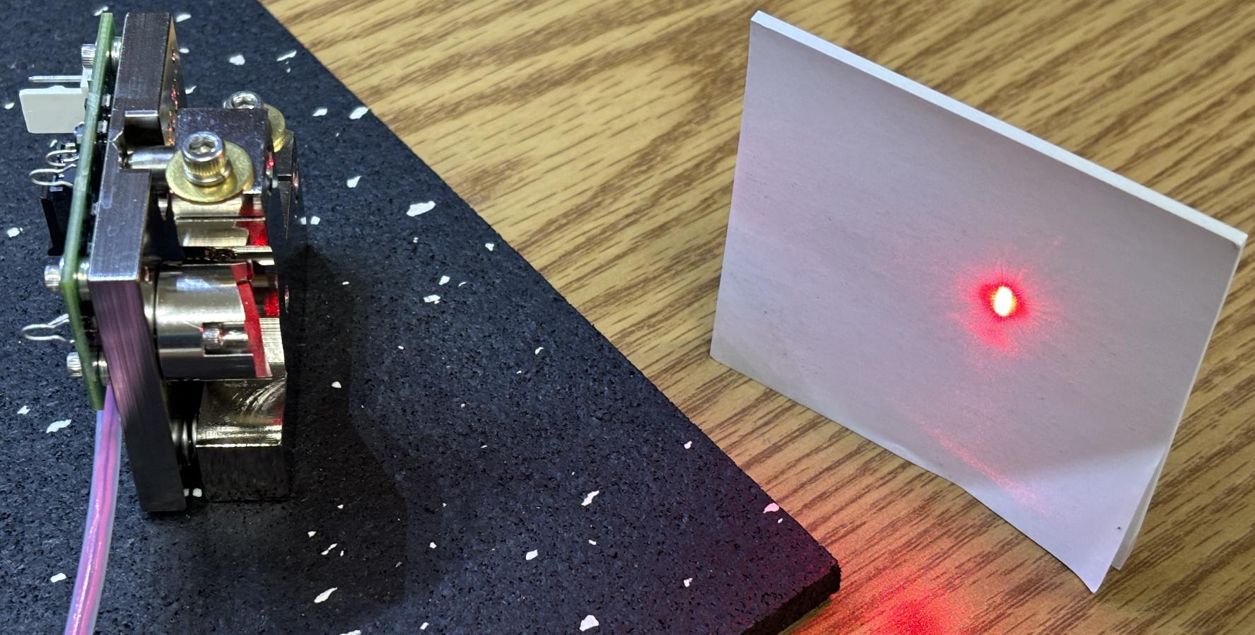
Two screws recessed deep into the aluminum frame are used to secure the output focusing lens and collar.
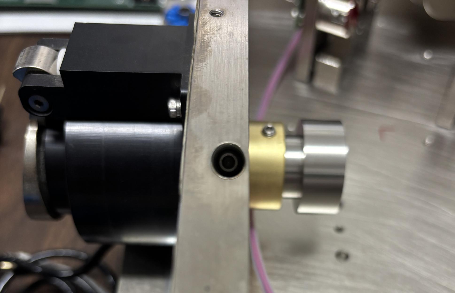
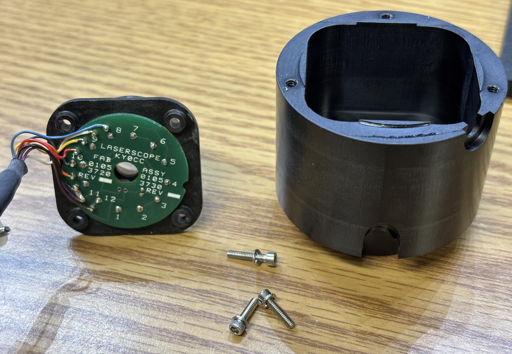
This is the fiber port assembly (0133-0280). It secures to the front of the resonator enclosure over the output aperture. It permits laser light to pass through into the optical fiber, while securing the fiber in place. A small PCB also detects the presence of a fiber and identifies its capability/model based on the pin arrangement. The arrangement of shorted pins is reported back to the rear panel board over the black cable. There is no logic contained within the fiber or fiber port connector pictured below. Only shorted pins are read by the RPB.
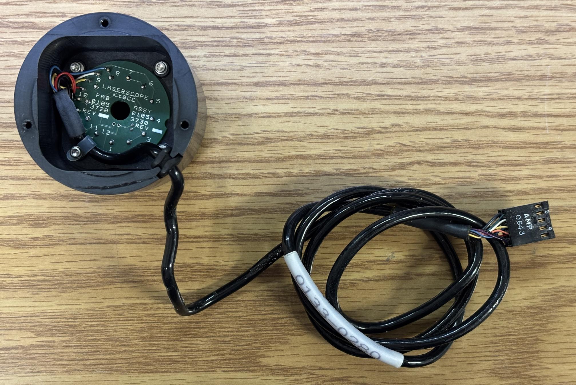
Earlier non-AMS Laserscope models also incorporated an RFID communication subsystem to read unique identifiers from the optical fiber and pair them with the smart card. Other Laserscope patents also mention the usage of precision resistors to accurately convey the fiber capabilities to the rest of the system, but we have not seen this implemented on any units. The only other notable component on this board is an AD590KF temperature transducer. This is used to detect overheating of this connection if there is a fiber alignment problem.
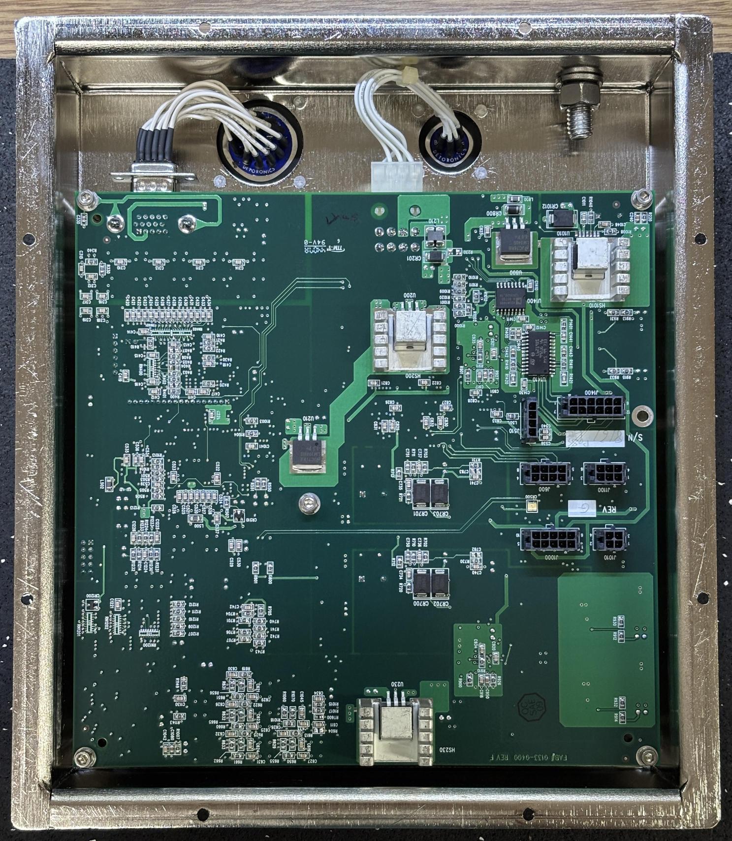
Mounted in a separate tray below the resonator is the Laser Control Board or Resonator Control Board (LCB) (ASSY# 0133-0440). The tray is still sealed by foil tape as connections from this board route directly via an opening in the baseplate to the components. This board has several responsibilities that include monitoring and controlling the crystal temperatures, controlling the aiming beam, monitoring the photodiodes, and managing the safety shutter. Two circular connectors are used to connect this board to the rear panel board. This board communicates digitally over CANBUS and RS-485 to the other modules and receives DC power from the rear panel board. The green "heartbeat" LED is also visible from within the resonant cavity when looking down at the board. Discrete connections from the various components within the resonant cavity pass through a rectangular opening and plug into several Molex Micro-Fit connectors on the LCB. During our testing, we determined that the LCB will immediately begin regulating the crystal temperatures once the board receives power. The heater drive circuit hits the TECs at around 2.5-5 V DC at first and then settles at around 0.55-0.65 V DC to maintain the temperature. The crystal carriers are warm to the touch, but not hot.
A table of thermistor measurements is provided below as a reference. Based on our analysis, the control board seems to keep the crystals at around 100 degrees Fahrenheit. A type-K thermocouple was adhered directly to the crystal mount for these measurements.
| STATE | AMBIENT TEMP | CRYSTAL TEMP | THERMISTOR RESISTANCE |
|---|---|---|---|
| POWERED OFF (COLD) | 79° F | 78.8° F | 9.58K OHMS |
| RUNNING (>5 MIN) | 79° F | 100-101° F | 5.45K-5.50K OHMS |
Taking a closer look as the laser control board reveals a high degree of complexity for some relatively simple functions. This board requires three separate DC voltage rails for input power. 24V, 5V, and 15V DC. Several regulators located on the reverse side of the board further regulate and convert the DC power to other voltages, such as 3.3V for the logic. Each TEC has its own independent channel (TEC0 and TEC1). The TECs are controlled by a LTC1923 and a series of power MOSFETS to switch the output. Several test points are present which can be used to monitor the TEC voltage as well as input power. There are also dedicated test points per channel for the TEC outputs and thermistors. It is surprising to see so many labeled test points on this board. The other boards within the Greenlight HPS have little to none. Other notable test points on this board include CAN (TP301) and +VCAN (TP300), which we used to inject 5V for the CANBUS transceivers with this board isolated from the others. The presence of several ADUM1400/1402 digital isolators leads us to believe that basically all digital control and monitoring lines are isolated from the MCU. The standalone ADC is likely used for thermistor/photodiode readings and the DAC is likely used for the aiming beam intensity adjustment. Interestingly, the safety shutter appears to be driven by an ST L6219 stepper motor driver. There is a variety of other components on this board, some listed below as well. We aren't completely sure what's going on with the two CMOS analog multiplexers, perhaps some signals are redirected based on the operating state of the board.
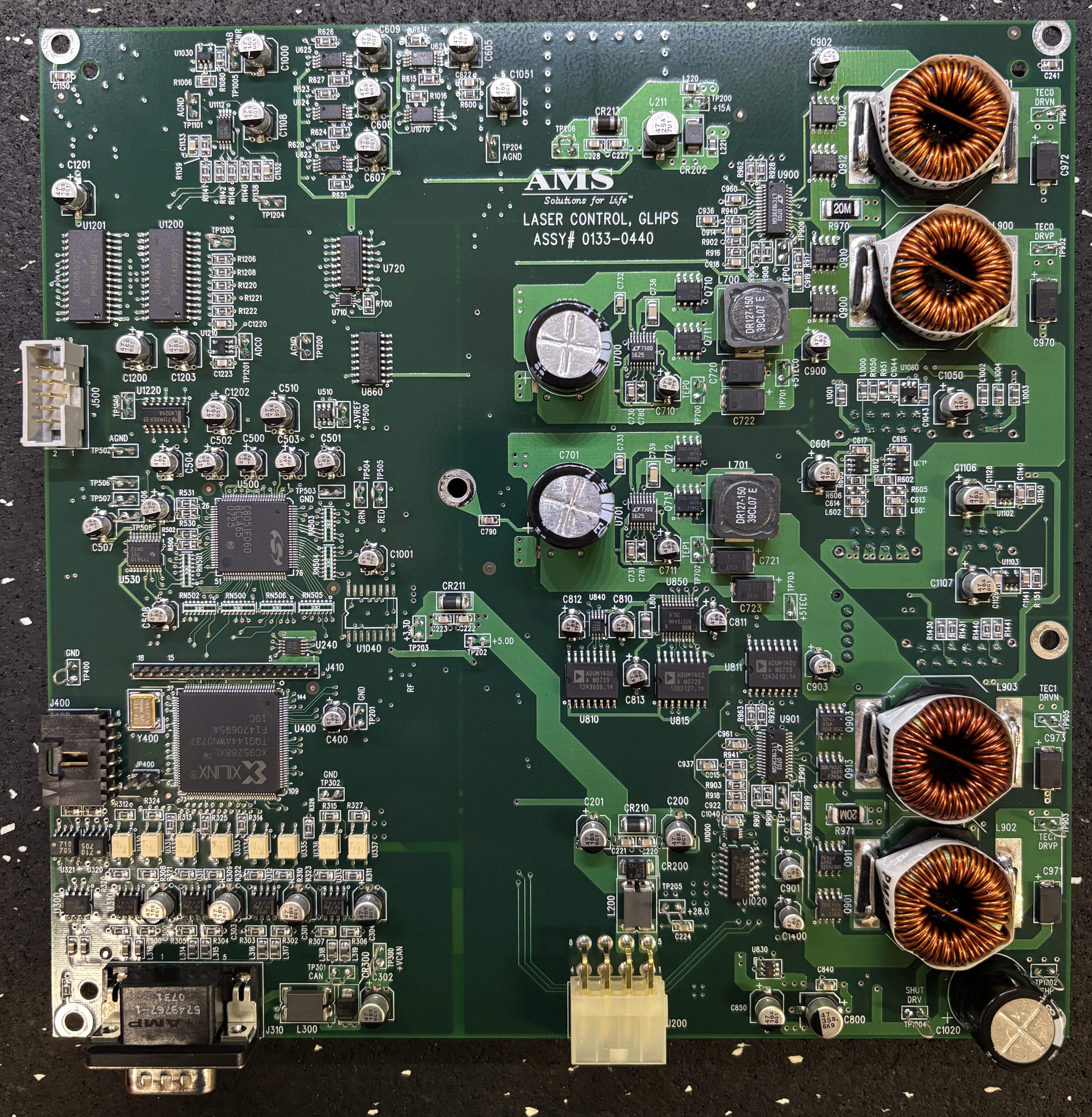
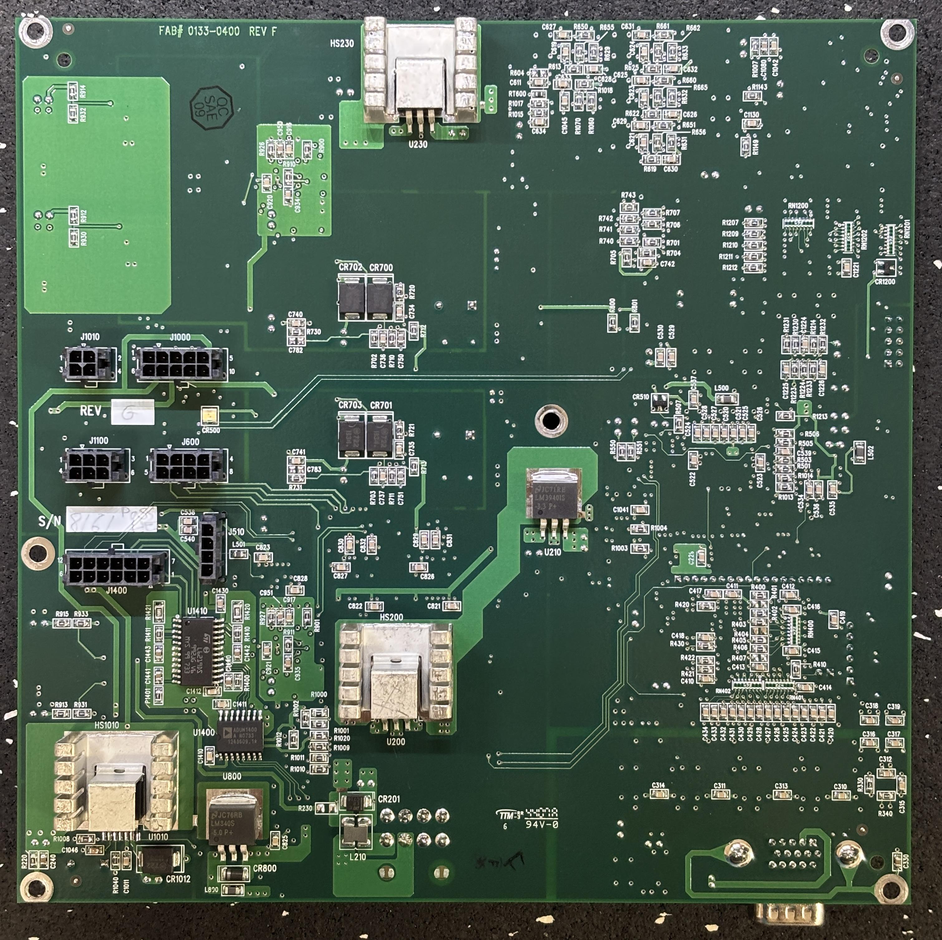
This table identifies the important components mentioned above, based on their silkscreen markings on the PCB.
| SILKSCREEN ID | PART | DESCRIPTION |
|---|---|---|
| U900/U901 | LTC1923 | TEC CONTROLLER |
| U1200/U1201 | DG406 | CMOS ANALOG MULTIPLEXER |
| U1020/U860/U720 | NEC PS2801-4 | PHOTOCOUPLER |
| U850 | BB ADS7844 | ANALOG TO DIGITAL CONVERTER (likely for TEC/therm measurement) |
| U530 | TLV5610 | DIGITAL TO ANALOG CONVERTER (potentially for aiming beam) |
| U810/U811 | ADUM1400 | DIGITAL ISOLATOR (potentially for TEC feedback) |
| U815 | ADUM1402 | DIGITAL ISOLATOR (potentially for shutter feedback) |
| U621, U623-U625, U1070, U1112 | TI L393 | DUAL DIFFERENTIAL COMPARATOR |
| Q*** | VARIOUS | IRF/IOR POWER MOSFET (TEC output drive) |
| U1410 | ST L6219 | STEPPER MOTOR DRIVER (shutter control) |
| U1400 | ADUM1400 | DIGITAL ISOLATOR (potentially for shutter control) |
| U200, U210, U230, U800, U1010 | VARIOUS | DC VOLTAGE REGULATOR |
The table below identifies the connectors on the LCB as well as their pin-outs.
| ID | TYPE | FUNCTION | PIN-OUT |
|---|---|---|---|
| J200 | Molex Mini-Fit (8-pin) | DC power input | 1. +24V DC 2. GND 3. +15V DC 4. N/C 5. +7V DC 6. GND 7. N/C 8. GND |
| J310 | DB-15 | CANBUS and RS-485 communication | Located on HPS CANBUS page - Click here |
| J510 | Molex Micro-Fit (4-pin) | UNKNOWN/UNUSED | |
| J600 | Molex Micro-Fit (8-pin) | Crystal TECs and thermistors | 1. CRYSTAL THERMISTOR 2. CRYSTAL THERMISTOR (GND) 3. CRYSTAL THERMISTOR 4. CRYSTAL THERMISTOR (GND) 5. CRYSTAL TEC1 NEGATIVE 6. CRYSTAL TEC1 POSITIVE 7. CRYSTAL TEC0 NEGATIVE 8. CRYSTAL TEC0 POSITIVE |
| J1000 | Molex Micro-Fit (10-pin) | Safety shutter | 1. OPTO POSITION SENSOR A OUTPUT (NO) 2. OPTO POSITION SENSOR B OUTPUT (NC) 3. +COIL (WHITE) [24V DC] 4. N/C 5. -COIL (BLACK) [GND] 6. N/C 7. OPTO POSITION SENSOR EMITTER GND 8. OPTO POSITION SENSOR EMITTER +5V DC 9. NTC THERMISTOR 10. NTC THERMISTOR |
| J1010 | Molex Micro-Fit (4-pin) | Aim beam | 1. +5V DC 2. ENABLE/CONTROL (0-5V) 3. GND 4. N/C |
| J1100 | Molex Micro-Fit (6-pin) | Photodiodes | 1. UPPER PHOTODIODE (BLACK) [PD CATHODE] 2. UPPER PHOTODIODE (WHITE) [PD ANODE] 3. UPPER PHOTODIODE (SHIELD) [PD CASE] 4. LOWER PHOTODIODE (BLACK) [PD CATHODE] 5. LOWER PHOTODIODE (WHITE) [PD ANODE] 6. LOWER PHOTODIODE (SHIELD) [PD CASE] |
| J1400 | Molex Micro-Fit (12-pin) | UNKNOWN/UNUSED |
Below are some useful resources regarding this resonator assembly. The patents and FCC information are worth checking out specifically.