This page encompasses our ongoing efforts to deepen our understanding and selectively modify elements the AMS Greenlight HPS laser system. Using a smart card to operate the laser is inconvenient, and so is using the built-in display touchscreen. This is especially true since the digitizers tend to fail on these units, making it impossible to adjust the output power setpoint. The system will still work and can be put in READY mode and activated using the foot switch, but it's still not ideal. It's also worth noting that the XPS manual makes several mentions of a service mode. One sentence gives us a glimpse of what that may look like: "Enter the Service mode by hooking up your laptop to the USB". From what we already know about medical technology systems, this will be the single most protected feature of this system. Modern vehicles aren't even this bad. Service mode is probably a dead end, but it was worth mentioning. This challenge is one of the reasons why we took this further, ideally we won't even need service mode.
Hacking the Greenlight HPS is very dangerous, and we highly recommend you DO NOT try anything that you read on this page. Interfering with the digital control system of a high power pulsed laser is a great example of tempting fate. Here are some things that could happen: you cook your retinas, you go blind, you burn the wall, you set the workspace on fire, you destroy the laser, you attract unwanted attention. There are many bad scenarios that could result from messing around with a dangerous system (like the Greenlight HPS) in this manner. So yes, we are basically telling you not to replicate any of the experiments or tests on this page. If you do, that's on you.
1. Understanding the Topology
The AMS Greenlight HPS laser system is comprised of several primary modules or nodes. These primary nodes all communicate with each other in a coordinated manner to ensure safe and controlled operation. In this writeup, we are focusing on the nodes that are part of the CAN/interrupt bus network. CAN/interrupt bus is terminology used by AMS in the XPS service manual. This really means CANBUS and RS-485 combined into one harness that loops through these nodes. The following nodes are connected together via a harness that includes CANBUS, RS-485 and an isolated transceiver DC power circuit.
- RPB: Rear panel board (aka: main control board)
- DLB: Data logging board
- LPS: Laser power supply (diode driver)
- DISP: User interface touchscreen
- LCB: Laser control board (resonator control board)
Importantly, this excludes the chiller, q-switch driver, and other ancillary components. Since those modules don't communicate over the CANBUS network, they were addressed separately. Return to the HPS main page to learn about those components. Starting with the basics, let's look at the path this harness takes through the nodes:
DISP J300 -> LPS J310 -> LPS J300 -> RPB J310 -> RPB J300 -> DLB J310 -> DLB J300 -> LCB J310
The display and laser control board (resonator) are end modules, with the rest having two connections, essentially an in and an out, but this communication bus has no direction. J300/J310 refers to the connection identifier, which is present on the boards in silkscreen and on tags attached to the harnesses. Since CANBUS requires termination, the two end nodes provide this termination resistance of 120 ohms.
2. Establishing CANBUS Communication and Being a Good Listener
CANBUS, most well-known for its use in vehicles, is a well documented communication protocol. It's surprisingly simple, resilient, and extensible. Getting started with CANBUS only requires a simple USB-to-CANBUS dongle. For this project we used an Innomaker USB2CAN board and a Linux computer. Numerous options are available, and some of the more expensive options are bundled with powerful software that simplifies the process of analyzing and probing the bus. In our case, we worked with the raw CANBUS data and developed a series of custom Bash and Python scripts to interact with the system over CANBUS. The first step of "hopping on the bus" was to decipher the pin-out for the J300/J310 harness. This correlates directly with the "Laserscope common logic" as we call it, which refers to the MCU, CPLD, CANBUS transceivers, and RS-485 transceivers found on the primary nodes listed above. Using continuity and resistance tests, we mapped out all the signals to pins on the J300/J310 DB-15 connectors.
| DB-15 PIN | DESCRIPTION |
|---|---|
| 1 | CAN_HIGH |
| 2 | +VCAN (5V DC) |
| 3 | RS-485 TRANSCEIVER #1 (U310) B |
| 4 | RS-485 TRANSCEIVER #3 (U312) A |
| 5 | RS-485 TRANSCEIVER #4 (U313) B |
| 6 | CAN_LOW |
| 7 | GND |
| 8 | RS-485 TRANSCEIVER #2 (U311) B |
| 9 | RS-485 TRANSCEIVER #3 (U312) B |
| 10 | N/C |
| 11 | GND |
| 12 | RS-485 TRANSCEIVER #1 (U310) A |
| 13 | RS-485 TRANSCEIVER #2 (U311) B |
| 14 | RS-485 TRANSCEIVER #4 (U313) A |
| 15 | N/C |
With the pin-out deciphered, we used a DB-15 breakout board which has both male and female connectors along with the terminal blocks to act as a "tap" for the harness. This allows us to connect and monitor each signal while keeping all nodes connected together. We connected CAN_HIGH, CAN_LOW, and GROUND from the USB2CAN adapter to their respective pins on the breakout board. Make sure to install the termination resistor/jumper on the CANBUS adapter, as it's essentially another branch from the bus and needs to be terminated properly. The next step is determining the CANBUS baud rate, we just guessed based on what most vehicles use, and turned out to be correct. The CANBUS baud rate is 500,000 bps, probably the most common option. You can determine the baud rate with an oscilloscope and cursors by measuring peak-to-peak and doing some math, but guess and check with common baud rates is usually faster. With the baud rate set correctly and the system powered on, we were met with a steady stream of CANBUS data, much like you would get from a car if you tapped into its CANBUS network. Here is what that looks like, this is a burst of messages transmitted in less than one second from power on. This was captured using the candump command from the can-utils Linux package.
10000503#146A4D964E
10000554#1205FF
100003B8#1400000000
10000354#1203FF
10000302#120100
10000345#00
10000359#120253
10060305#800003020018
10000154#12017F
08030148#120100
10000167#120000
10020141#1170
1003017E#120001
08030548#120100
10000503#146A4D964F
Feel free to do your own research about CANBUS, but it's actually a really neat protocol and is quite easy to understand. The basic concept is that all nodes transmit data on a common bus, and all other nodes can see that data. Transmissions include an identifier (and priority) and a data payload. Nodes can transmit data using one or multiple IDs. Based on the ID/priority, a node can either act on or process the message, or ignore it. Imagine being in a room of people talking and having the ability to only listen to specific voices while ignoring the others. There's of course way more to CANBUS than this, such as acknowledgement, error handling, and priorities, but those are the basics. CANBUS is generally unencrypted, but it can be. Luckily, the Greenlight HPS does not encrypt any CAN traffic. Using the candump command on a Linux computer, we captured all CANBUS data from startup to shutdown, and individually captured running sessions where we put the HPS in to ready mode and turned on the beam. This allowed us to get a general idea of what's happening and when. Timestamps are useful to pinpoint blocks of data when something interesting is happening, such as when laser emission is occurring. However, without a mapping of CANBUS IDs and their purpose, it's just a mess of data. Using a combination of manual analysis and help from AI, we mapped out some IDs and constructed a rough understanding of what they represent. When designing a system, the mapping of raw CANBUS data/IDs to physical values or descriptions is contained within a DBC file. These DBC files are of course proprietary information, and not willingly provided by OEMs. There is no DBC file for such as niche system like the Greenlight HPS. However, if you're into cars, the opendbc project is worth checking out.
Having said that, it is possible to slowly map out functions through trial-and-error and watching data values change when you physically interact with the system. Arguably the most useful thing we have done throughout this process was to leverage AI to help us develop a custom Python script that displays as many parameters as possible in a human-readable format while listening to the CANBUS of a live system. The program lists out system status, various setpoints and parameters, and clearly displays what's currently happening. It also lists out every CANBUS device ID, value, the last time it was transmitted, and a description. This is complemented by a confidence level that correlates to whether we were able to verify the true purpose of the specified ID/value. Using this program, and several iterations of it, we figured out how the system ramps up and down during its self test. We also learned what CANBUS device IDs correlate to the foot pedals by pressing them and watching the data values change. One major advantage of this program is its ability to replay captured CANBUS data. This is much safer than connecting it to a live system. The program is available for download at the bottom of this page. REMINDER: We do NOT recommend using this on a live system, as tapping into the CANBUS of a high energy laser is dangerous. A safer option is to download the program and example data that we captured, and run the program on your computer using the replay feature, without even connecting a CANBUS adapter. This is much safer and allows you to watch a HPS startup and operate in realtime, while examining the CANBUS data.
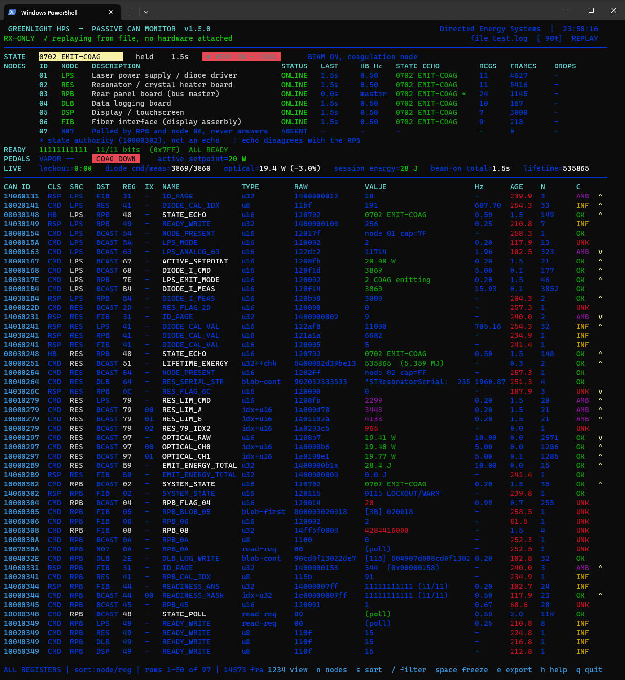
Skip to the bottom of the page or download the Python program and example capture below. After installing Python and the required dependencies, replay a capture with the following command: python hps_monitor.py --replay test_capture.log
3. Isolating Nodes and Deciphering Their Communication Patterns
When many nodes are transmitting on the CANBUS at once, it's quite difficult to determine which IDs belong to which nodes. That information is nice to know when reverse-engineering a system. To help narrow down individual CANBUS device IDs to individual nodes, we used the highly scientific process of unplugging various nodes and analyzing how traffic on the bus changed. This of course results in the Greenlight HPS panicking, throwing an error, and often shutting itself off. Every node must communicate in a well behaved manner for the system to operate. Otherwise it'll latch a fault and refuse to do much of anything. Disconnecting the DLB specifically is entertaining as the display screen will just show the text "Goodbye" and the system will cease most operations. What we learned is that the RPB (rear panel board) is the bus master, not only does it provide the +VCAN 5V signal and ground for the entire network of transceivers, but it also polls the other modules for their status and state over CANBUS. The LCB (laser control board) broadcasts its status and some parameters such as photodiode measurements on the bus unprompted, while polls can reveal additional parameters. The DLB (data logging board) does not broadcast much, but must consistently respond to a keep-alive poll or else the system will panic and shut down. During various states of operation, many more IDs are active on the bus. During startup, all the nodes enumerate, announce their presence and broadcast several parameters that include serial numbers, software versions, and setpoints. Once the system finishes booting and arrives at the STANDBY (idle) status, the bus quiets down significantly. When the system is put into READY mode and laser emission is activated, many more IDs begin broadcasting and the bus gets busy.
4. Replaying Captured Data
We started this journey by capturing all CANBUS data from a full startup sequence, to idle, and to laser emission. We isolated just the touchscreen display, powered it, and tapped into its CANBUS connection directly. It's important to re-iterate the need to provide the +5V DC VCAN input and ground either using test points on the board (if available) or pins on the DB-15 connector. The transceiver power circuit for all modules is provided by the RPB. This seems to be an isolated circuit, perhaps as a safety feature. Dropping this circuit would immediately kill all CANBUS and RS-485 transceivers, subsequently leading to a system shutdown. We began replay of the captured CANBUS data shortly after power was applied to the display (outside of the Greenlight HPS). Waiting until the screen displayed "please wait" seemed to help. If the replay is started too early or late, this exercise will not work. If everything was done properly, the display screen will react in the same way as it would if it were attached to a functional system. It counted down and arrived at the home screen. Most impressively, it indicated emission as per the captured sequence, even without a smart card inserted! It also displayed the session energy and laser on time, just as it was in the capture. The display is clearly not performing any active checks on the other modules, it just reads their states and likely answers to any requests regarding smart card validity and the overall system ready state.
Unfortunately, this exercise was not successful on other modules such as the LCB (laser control board), or the entire rest of the system. Removing the display touchscreen and replaying data on the CANBUS causes the other modules to enter an error state, as evident by a RED heartbeat LED (typically green during normal operation). Clearly, the other modules are performing active checks or expecting session-specific data from the display board.
5. Simulating/Impersonating the Display Touchscreen
Following the unsuccessful replay attacks, we made several attempts to design and test a program that simulates all functions and CANBUS communication from the display screen board. The display screen does several things. It broadcasts a monotonic counter that constantly increments upwards, broadcasts a real time clock, echoes the ready state, responds to system arm requests (prior to emission), and of course displays operating parameters and errors. Using AI and some custom Python scripts, we made several attempts at a "display screen simulator". This program mimicked as many function as possible from the display screen, basically impersonating it. The program broadcasted the same counter, clock, and echoed the system state. It also responded accordingly to polls by other modules. Theoretically, this should have worked, allowing the rest of the system to boot up all the way, run the self-test, and enable the laser. Unfortunately, this was not successful. The system booted up much farther with the simulator program running, but still went an error state, seemingly right as the self test was beginning. We presume this is because our simulator did not participate on the RS-485 interface at all. This interface has eluded us up until this point, and we have all but ignored it. One other possibility is some sort of dynamic handshake taking place between the display and another module, complex enough that our simulator program was not able to replicate it.
6. The RS-485 Nightmare
There are four individual RS-485 channels, consisting of an A and B terminal, that route through the same harness as the CANBUS. Unlike the CANBUS, we've had absolutely no luck in capturing and deciphering any data from the RS-485 interface. We have not been able to determine the baud rate, or even whether it's a full duplex or half duplex arrangement. Data seems to come in bursts, rather than a constant stream like what is present on the CANBUS. Perhaps our probing and capture methods are insufficient, but even attempting to decode signals from the interface with an oscilloscope has been unsuccessful. We call this the RS-485 nightmare because it seems to be the one aspect of this system we have not yet figured out, and it's also likely to be the one thing holding us back from fully taking control of the system. One notable thing we did learn while tirelessly probing the RS-485 interface is that sending any data to it (assumed invalid, since we don't know what's valid) causes the system to error out and stop laser emission. Our understanding is that the RS-485 interface is primarily used as an interlock circuit, and a "last resort" method for preventing a dangerous situation. The CANBUS network would have to fail spectacularly for this to be necessary, as even the bus going down causes a fault and subsequent shut down. Perhaps in some edge case valid data could be still streaming on the bus, and RS-485 could be used to bring the system down if one of the nodes figures out something's not right. This is further reinforced by the description of a CAN/Interrupt bus in the XPS service manual. Since CANBUS is called out by name, the interrupt bus is likely referring to RS-485.
7. Microcontroller Exploits
Another reverse-engineering avenue is to dump the firmware stored in the Silicon Labs C8051F0 MCU. Each major node has a variant of this MCU, and we believe they are what's responsible for the CANBUS and RS-485 communication between nodes as well as managing their respective node. What makes this even better is the presence of a JTAG header on each board, which is pin-for-pin compatible with the standard ISP debug tools. We traced the pins back to the MCU to verify this. In theory, connecting a JTAG debug tool directly to this header with the included ribbon cable should allow us to at least connect to the chip. Getting this firmware and decompiling it would be extremely useful. From decompiled firmware, we should be able to reconstruct PID loops, CANBUS syntax, and information related to the RS-485 interface. We have made multiple attempts at this, but have not been successful. We're currently acquiring another debugger, just to rule it out. It's also possible that the JTAG interface on these chips has been disabled. This seems unlikely though, as the JTAG headers are populated on each board with the Silicon Labs MCU. Although we have not yet been able to confirm this, these chips likely have protection bits set to prevent firmware readout through programming headers. If this turns out to be true, the book "Microcontroller Exploits" written by Travis Goodspeed will likely prove to be useful.
8. The Last Resort (Custom Control Boards)
We are working on another solution in parallel to the CANBUS and RS-485 reverse-engineering. This solution is is a guaranteed success, but it has several drawbacks and complexities of its own. We are currently working on designing and testing a series of circuit boards that are intended to be drop-in replacements for the existing boards that control the various modules of the Greenlight HPS. This kit will consist of three boards/assemblies. The first board will replace the digital control board housed within the Vuemetrix diode driver. This is actually the easiest one to design and fabricate, as it only needs to enable and trim the Vicor DC-DC converter modules. It will be controlled over RS-232 or a simplified CANBUS network with documented definitions and commands. The second board is slightly more complicated as it will replace the rear panel board, which brings everything together. This will act as a GPIO board that monitors and controls the chiller, monitors the various flow switches and temperature sensors, controls the q-switch driver, monitors the interlocks, and monitors the foot switches. This board will likely be based around an Arduino Mega, as it has plenty of I/O and serial interfaces. It will also feature CANBUS, USB, and RS-232 communication. Again, when you design the communication protocol, it is much more straightforward as you actually know what commands to send to get the desired outcomes. The last board is arguably the most complicated as there are two distinct challenges. This board will be a drop-in replacement for the laser control board contained within the resonator assembly. The first challenge is the fact that the resonator must be unsealed to access and replace the laser control board. This board shares the same cavity as the optics, and specifically the LBO crystals, which are sensitive to moisture. If any part of the resonator is unsealed, you likely have only a couple of days to properly reseal the cavity, provided the environment is reasonably well climate-controlled. This isn't an exact science, but if you were to complete this operation within 4-8 hours, inside an air-conditioned, relatively clean room, it should be fine. The main drawback of the resonator's design is the lack of sealing gaskets. It uses foil tape instead, which needs to be replaced with the same foil tape or a reasonable substitute. It would also be wise to replace the desiccant during this process. The second challenge is replicating all the critical functions performed by this board. It manages the crystal temperature by driving the TECs, monitors the photodiodes, controls the shutter, and drives the aim beam. These functions alone are not very complicated, but integrating them all onto one board is quite a challenge. Just look at how complicated the OEM board is! It's still doable, but we do have an interesting workaround to this particular challenge. Custom harnesses can be made, along with a simple breakout board that simply jumpers all the required connections to the sealed twist-lock connectors on the bottom of the resonator. This allows for a very quick resonator seal and unseal (~1 hour), just to install the jumper harness and board. With all critical connections moved to the external connectors, unlimited time can be spent designing, testing, and revising custom boards to drive these components. Based on the amount of pins available on the connectors, this should be possible, provided some grounds are combined. This is a tempting option that we may pursue before fully redesigning the board. At that point, off the shelf modules could be used to replicate the required functions (TEC drive, shutter, etc.). If we design and fabricate these boards, safety is still going to be a priority. This laser system is capable of causing serious damage, so it's critical that all interlocks are honored when retrofitting the system in this manner. Our goal is really just to get around the inconvenient smart card and lifetime usage system. All other interlocks (shutter, external interlock, fiber socket detector, chiller temp, flow switches, etc.) should be maintained to prevent damage to the system and mitigate the safety risks.
9. Miscellaneous Components & Remarks
As we continue working with this system, we will update this page and related pages. We also have a running document of all pin-outs and connection descriptions. That can be accessed via the link below.
Check out the links below to learn more about the solutions and products we used throughout this endeavor.
- HPS Monitor Python program
- Example CANBUS data capture (startup to coag beam)
- NTcanTools - Bash script for automating common CANBUS debugging/analysis functions
- CSS Electronics - High end CANBUS development tools and hardware
- CSS Electronics - CAN DBC file explained
- opendbc (for cars)
- Live LaserSystems TecDRIVE Lite (suitable off the shelf TEC driver for the LBO crystal heaters)