The Xcyte series from Lightwave Electronics/JDSU is a Quasi-Continuous Wave (CW) DPSS laser with a wavelength of 355 nm and a maximum output power of 20-150 mW depending on the model. These lasers were intended to replace traditional gas lasers such as HeCd (Helium-Cadmium) used for application such as flow cytometry and silicon wafer inspection. The Xcyte is referred to as Quasi-Continuous Wave because it's actually a pulsed laser system that operates at a frequency of 100 MHz. This is achived with a built-in 100 MHz mode-locked oscillator. This Pulse Repetition Frequency (PRF) is so high that in most low-bandwidth applications, it behaves as a true CW laser. Only in extremely sensitive and high bandwidth applications would the Quasi-Continuous Wave nature of this laser system become an issue. The laser head is quite a behemoth weighing in at around 30 lbs and measures 18" x 6" x 7". It's a very sturdy milled aluminum chassis with several openings and cutouts. Unfortunately, this laser system is not operational due to a fault within the controller. We are working on repairing the controller, or sourcing a suitable replacement. Once we get the system up and running, we will be sure to update this page!
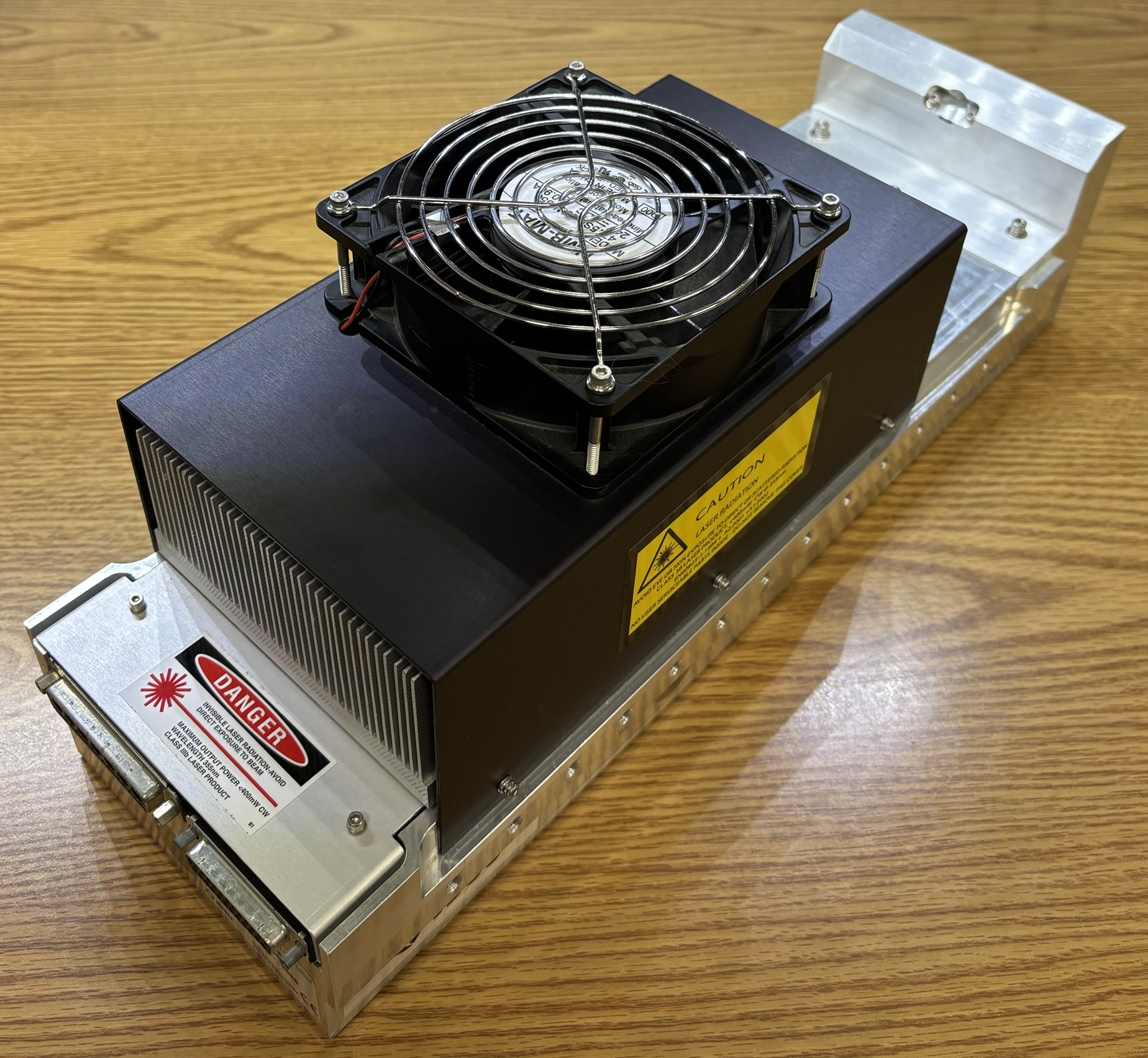
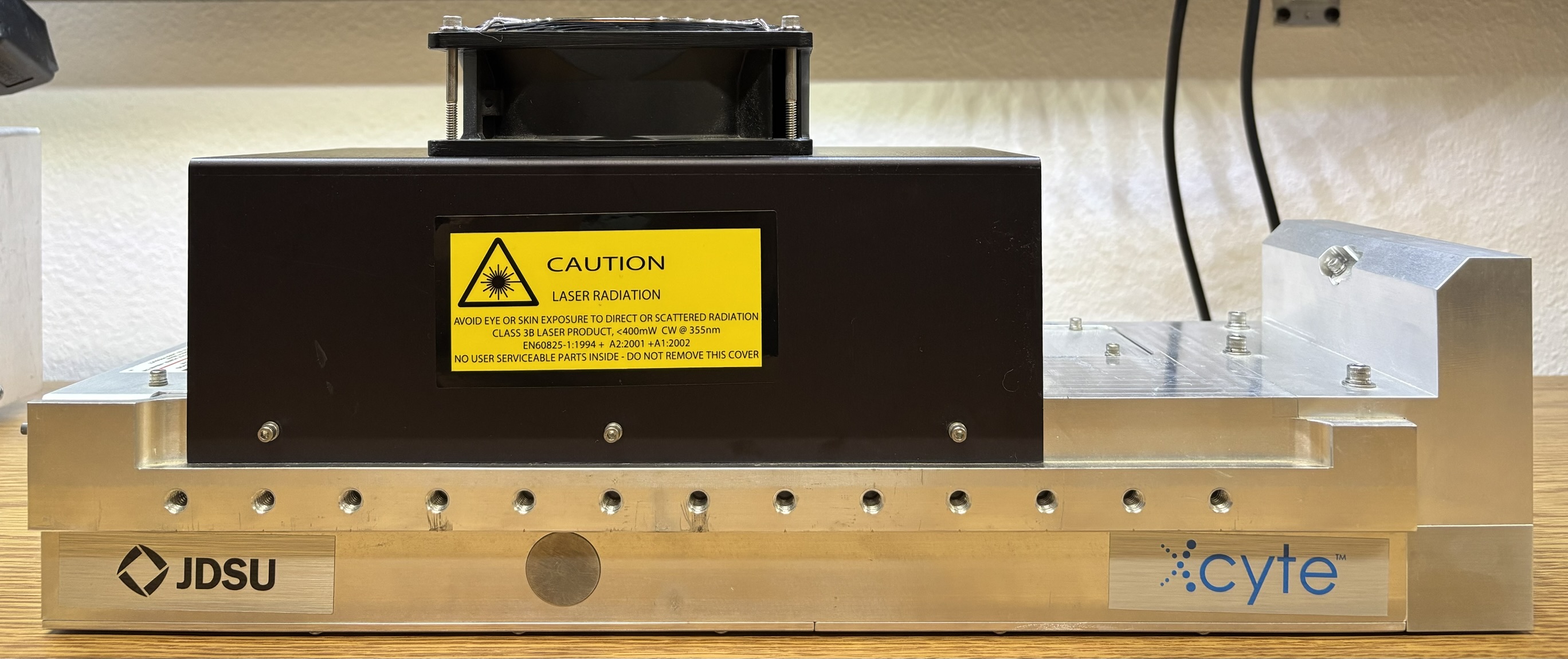
The design of this laser head is a bit unusual, compared to other DPSS units. All of the optical components including the pump diode are contained within the bottom aluminum structure, and are accessed by removing two aluminum plates on the bottom of the case. The TEC is mounted to the top and sandwiched between the heatsink (under the black plate). Mounted above the heatsink is the cooling fan. There are several threaded holes on the side of the aluminum casing for mounting the laser head.
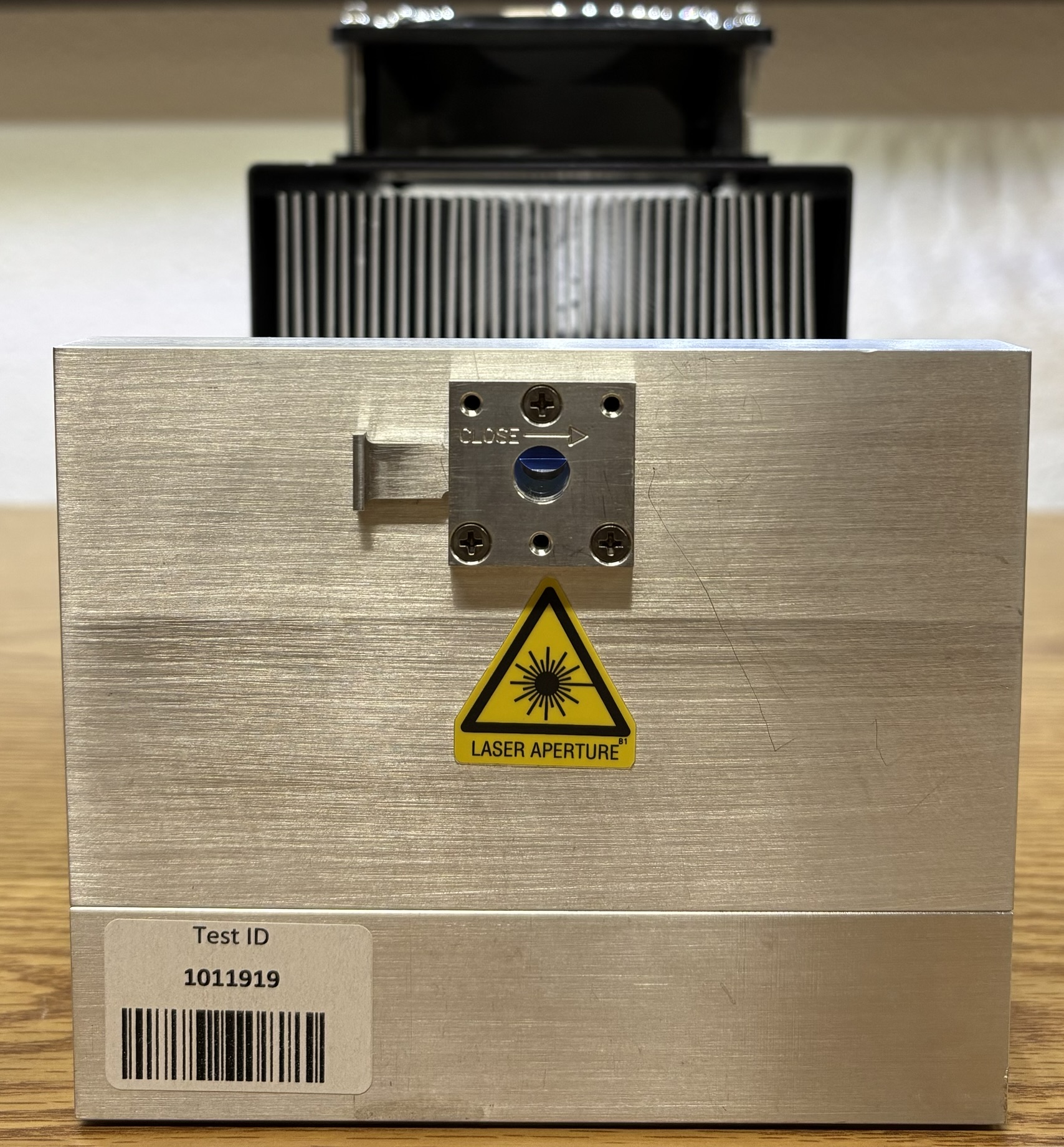
On the front is a simple beam shutter that has threaded holes for mounting attachments such as fiber-coupling adapters. This particlar unit has the optional periscope, which directs the beam up a few inches above the resonant cavity and then out the front. Normal models just emit the beam about half an inch from the bottom. This periscope option was useful when the Xcyte replaced a gas laser in a piece of equipment that required the beam to be at a specific height.
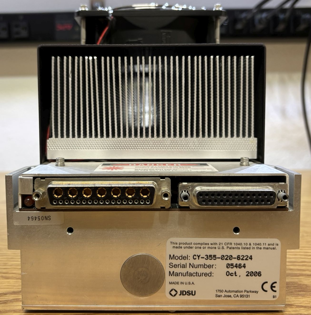
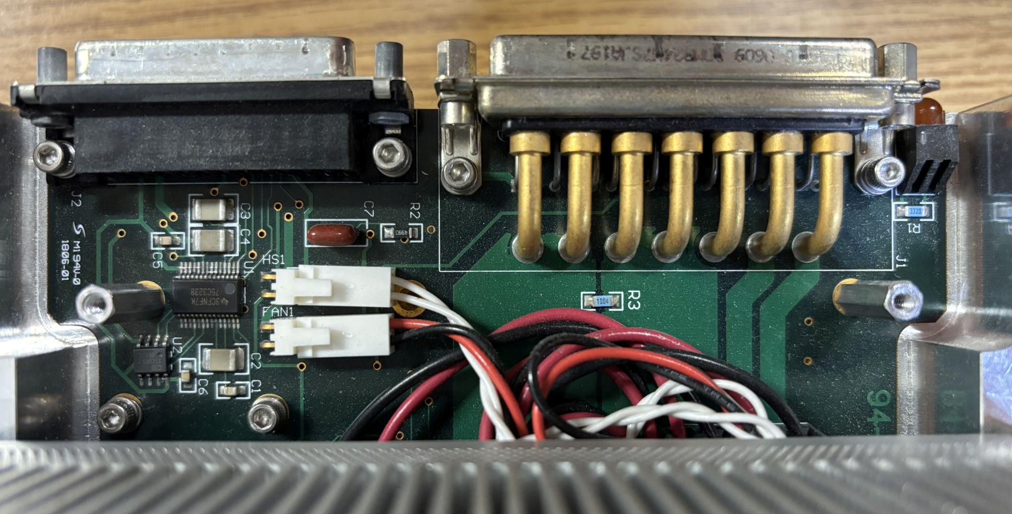
On the back of the laser head we can clearly see through the heatsink and see the two umbilical connectors. The connector on the left is a bizarre DD-24W7 that carries the high current connections for the pump diode, as well as some lower power sensing signals. These connectors are a hybrid of the typical D-SUB connector with some additional, larger pins and sockets. These are often seen in RF applications with small coaxial jacks embedded in the connector. In this case, the connector just includes 7 additional large pins/sockets used solely to carry large amounts of electrical current. The connector on the right is just a standard DB-25 for temperature sensors, interlocks, monitoring, etc.
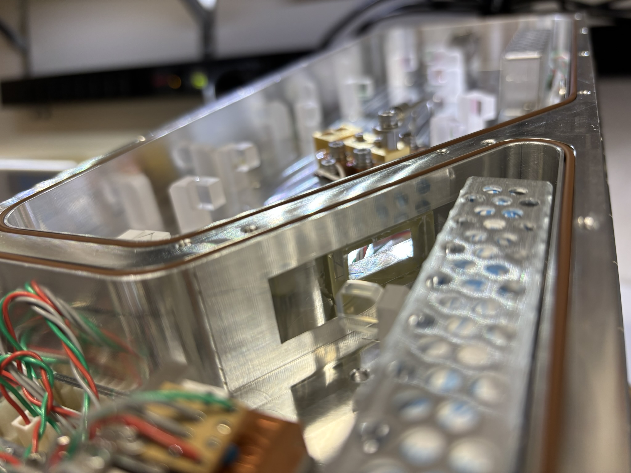
On the bottom of the laser head are two access covers. They are sealed with a gasket and can be removed to reveal the resonant cavity and optical components.

Below is yet another beautiful example of a DPSS resonant cavity! Actually two cavities, which are hermetically sealed and separated from each other.

There is a small glass window that is glued to the aluminum wall that separates the two cavities. Laser light passes from one cavity to the other through this window.
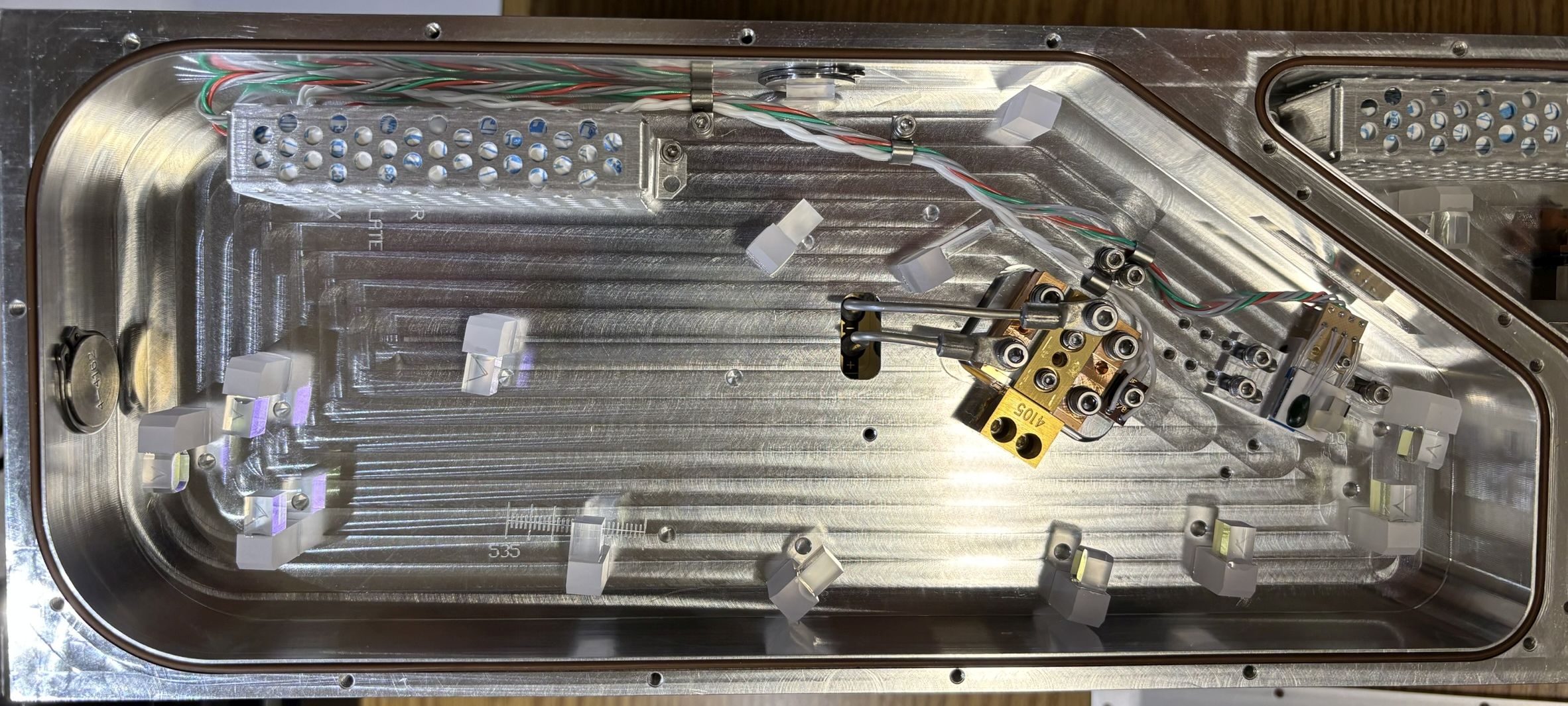
This is the pump diode and SBR (Saturable Bragg Reflector) cavity. A diode laser bar directly pumps an Nd:YAG gain medium. The SBR is located on a small pedestal with a TEC and thermistor to monitor the temperature.
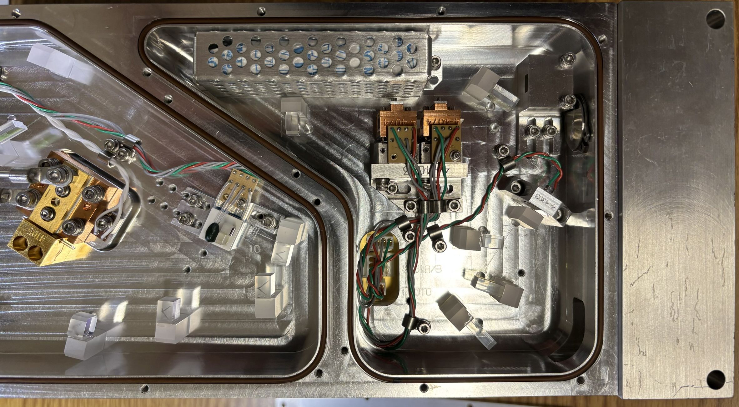
This is the SHG (second harmonic generation) and THG (third harmonic generation) cavity. The final output is sent up through the periscope to the front output aperture. There is a photodiode which measures a reflected portion of the beam for output power control and monitoring.
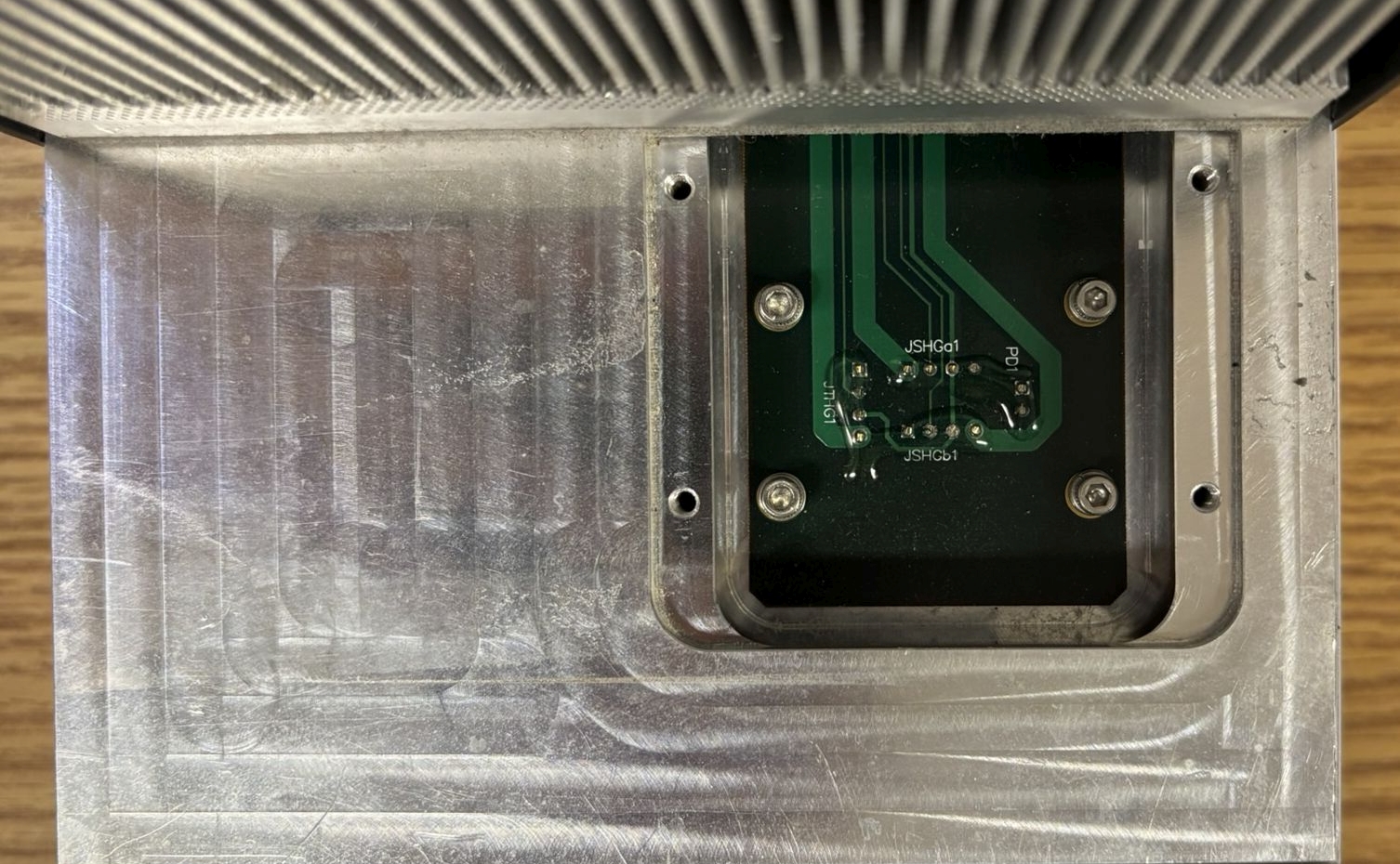
There is a small access cover on the top of the laser head near the front. This can be removed to reveal solder connections for the crystal heaters and sensors located within the resonant cavity below.
Removal of the rear top cover reveals a small circuit board that contains the umbilical connectors, status LED, and some small ICs used to report details back to the power supply. A thinner section of this circuit board continues down the length of the laser head to the access cover that was mentioned earlier. This board also serves as a breakout for the TEC, fan, and all optical components.
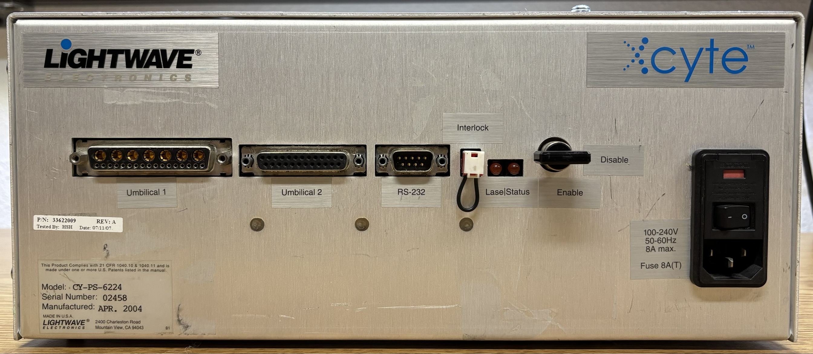
The controller intended for use with the Xcyte laser head is the CY-PS by Lightwave Electronics/JDS Uniphase. It's a plain aluminum box that measures 13" x 11" x 6" and weighs around 15 lbs. This controller is not functional and is the reason why this laser system is inoperable. The controller does turn on, the fans will spin, but neither external status LEDs illuminate. There is no activity or response from the serial port at all. It does supply power to the laser head, but there is no laser emission. So far, we have not yet been able to identify and resolve the fault with this controller. The only side with any notable features and components, other than ventilation holes, is the front. Starting from the left is the umbilical 1 and 2 connectors for the laser head. Umbilical 1 is the strange DD-24W7 connector that was mentioned earlier. Umbilical 2 is just a standard DB-25 connector. Next is the RS-232 serial port for monitoring and control by a computer. After that is a remote interlock jumper, two status LEDs, and the interlock keyswitch. Lastly is the AC input socket and power switch.
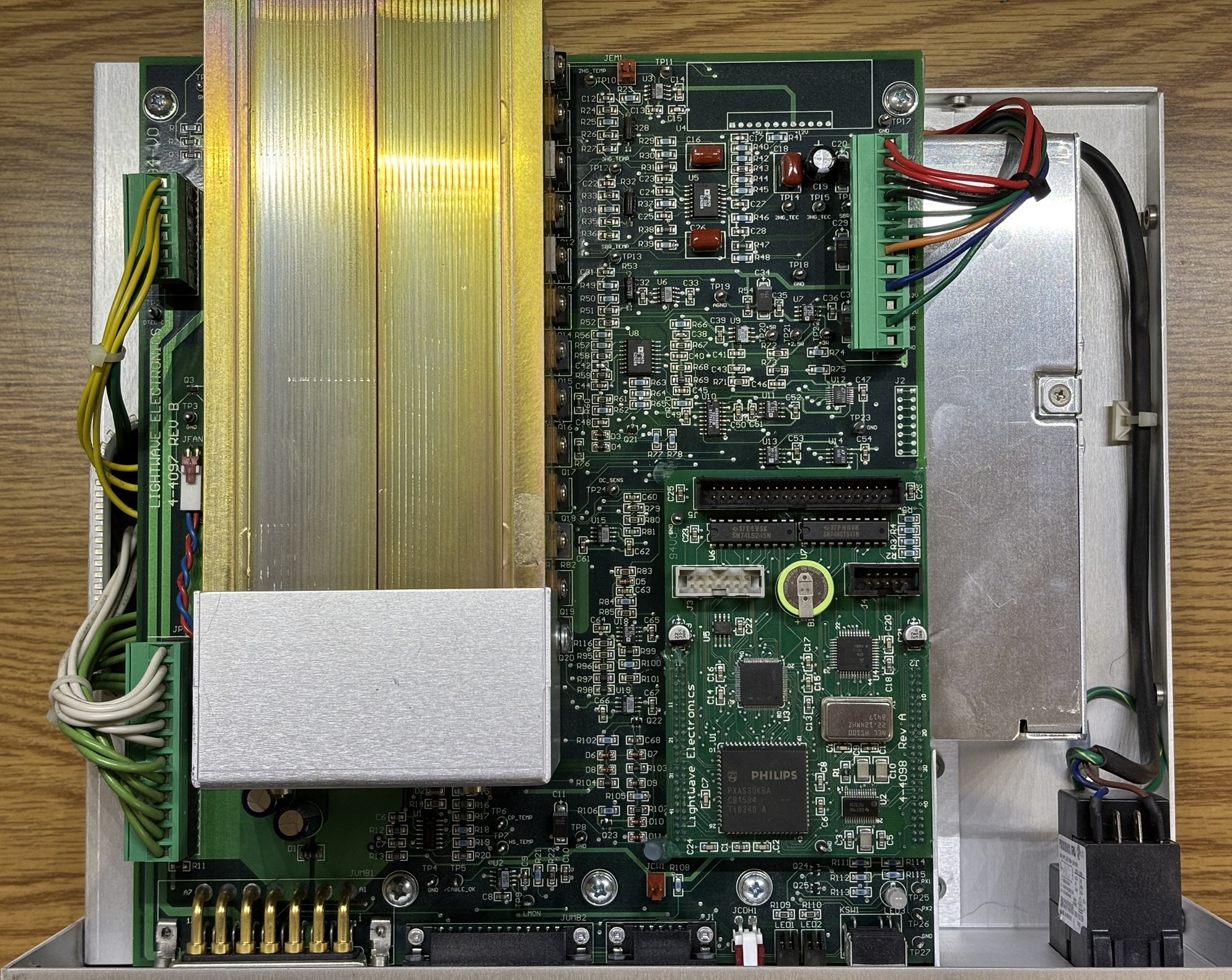
With the cover removed, we can see the large motherboard, heatsink, fan, and power supply (below board) contained within the CY-PS controller. When the controller is powered on, the only signs of life are the fan spinning and the internal bi-color LED on the motherboard lights up red.
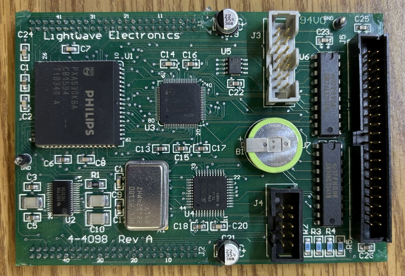
This is the digital control/processor board of the CY-PS controller. It mates to the large motherboard using two sets of dual-row pin header connectors. It is responsible for controlling and monitoring the components within the system. It also interfaces with the RS-232 serial port. We suspect the failure is located within this board or related to some other digital component. It seems like a logic failure or "lights on, nobody's home situation" where all power rails check out fine, but there is just no digital activity, the system does nothing other then power on. We did measure the frequency of the crystal, which matched the target ~22 MHz, so at least we know that part is working.
Interestingly, the actual power supply contained within the CY-PS controller is an off-the-shelf COSEL ACE900F series modular power supply. We have seen these before in other laser systems. They are very high current and low voltage DC power supplies with a wide range of applications. The power supply is capable of around 800 watts of combined DC output power. Since this is a modular unit, it accepts a wide-range AC input and has several DC output rails. The DC rails are listed below along with their functions in this laser system:
- DC +/- 12 V (3.2 A) - Control logic
- DC +/- 5 V (7 A) - Control logic
- DC 24 V (14 A) - Heater/TEC
- DC 3.3 V (60 A) - Pump diode power
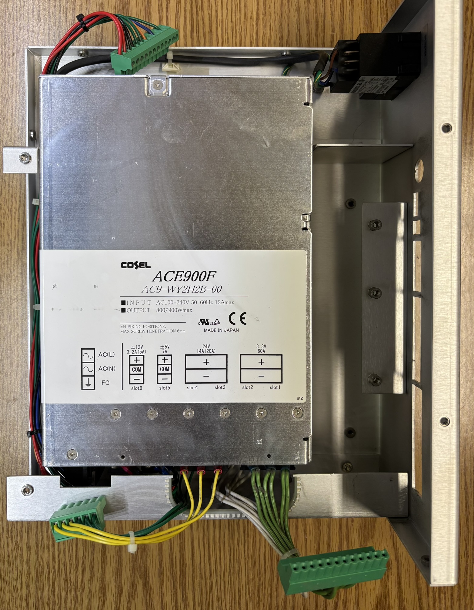
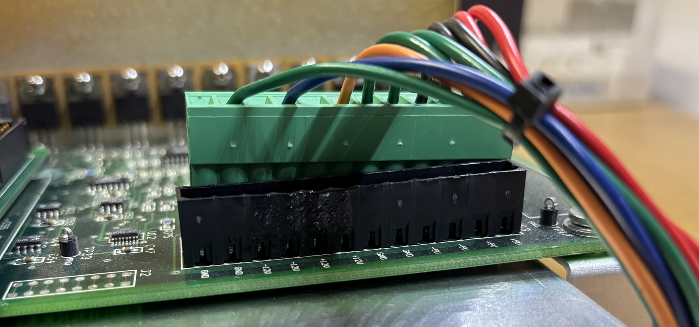
We tested all voltage rails from this power supply and they were spot on. Unless it's a stability or current carrying issue, we do not think the COSEL modular power supply is at fault in this case. We ensured DC power at least makes it to the motherboard through the connectors. Interestingly, one connector appears to have melted a bit, but is still making good connection. Perhaps this is related to our issue. Unfortunately, there is so little information available for this laser system, controller, etc. We don't even have a pin-out. We spent hours troubleshooting the controller and arrived at the conclusion that there must be something wrong with the MCU board or digital control circuitry. Everything else looks fine and tested out okay, the fans run at idle speed when the system is powered on. Also, the lack of activity from the status LEDs or serial port lead us to this conclusion. It does run the heater in the laser head, which gets a bit warm after a while. Based on images of these CY-PS controller, the status LED should come on when the controller is on, even when it's not connected to a laser head. It's worth noting that the datasheet does mention a ~20 minute warm up time for the Xcyte laser system. If you have an Xcyte system, be sure to give it at least 30 minutes to warm up before calling it a dead laser!
