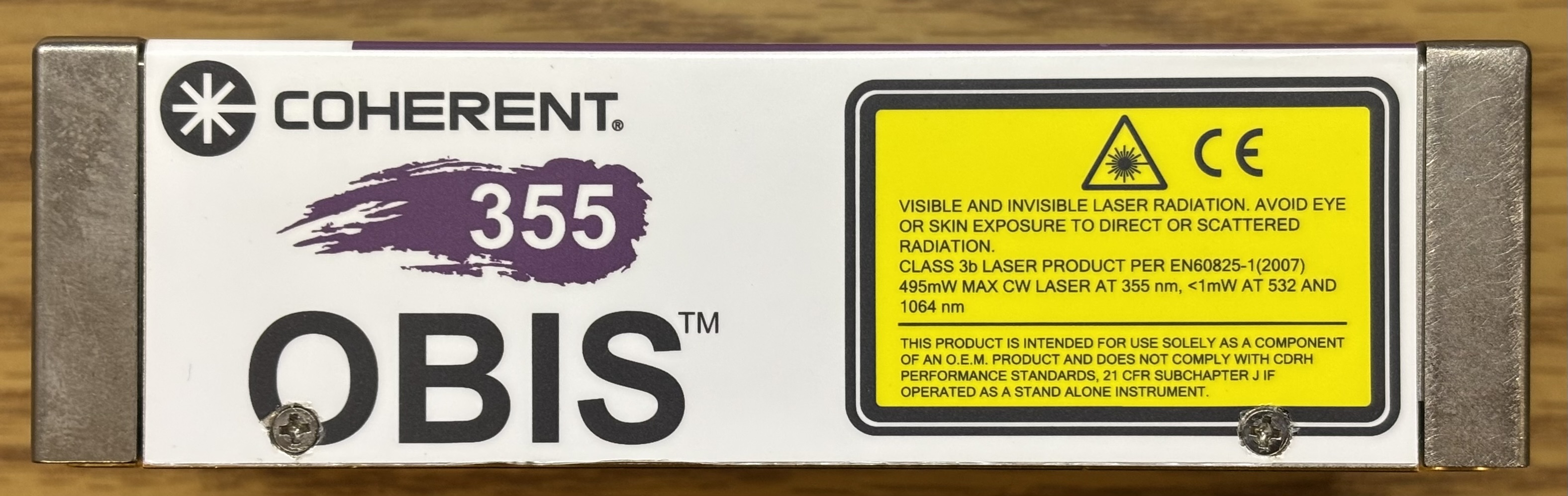
The Coherent OBIS LG 355-20 is a self-contained, low-noise, CW OPSL laser that emits up to 25mW of 355nm (UV-A) laser light. Similar systems are available with a maximum output power of 50mW. The OBIS is a high precision instrument that regulates the temperature of the optics and diode current more precisely than we have seen in other laser systems. This system is an ideal choice for scientific applications such as flow cytometry, semiconductor inspection, and confocal microscopy. Much like the CUBE lasers from Coherent, the OBIS module contains all of the necessary electronics and control circuitry to operate the laser diode along with the temperature-sensitive optics. All that is needed to operate the OBIS LG laser system is a suitable DC power supply and a thermally-controlled mounting surface such as a heatsink and fan. A computer is required to control the output power over the RS-232 serial interface or USB and monitor system parameters. Other lasers from Coherent, such as the Sapphire, require a dedicated controller board as the laser head only contains some of the components necessary for the system to function. In the Sapphire, current-intensive functions such as TEC control and diode power are handled by the dedicated controller. The OBIS integrates all control logic within the main enclosure.
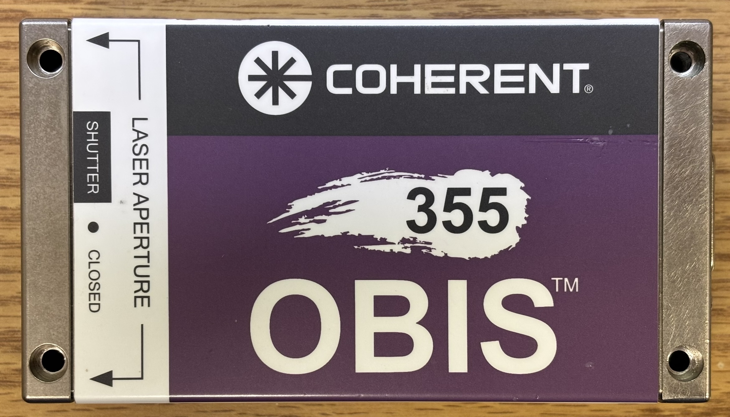
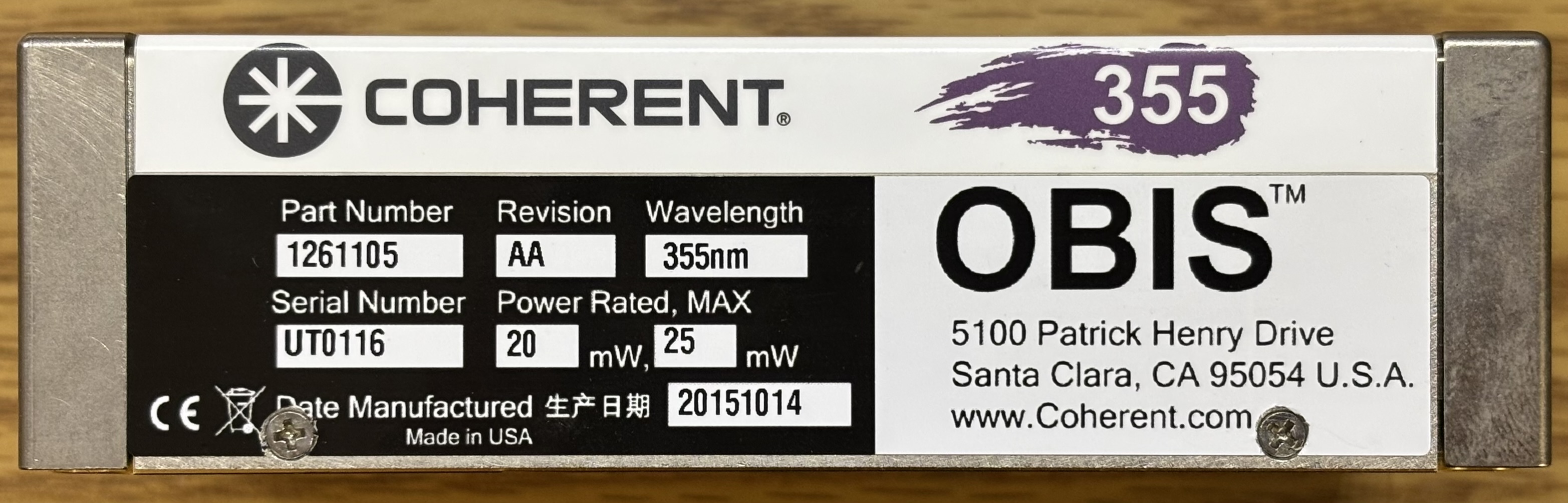
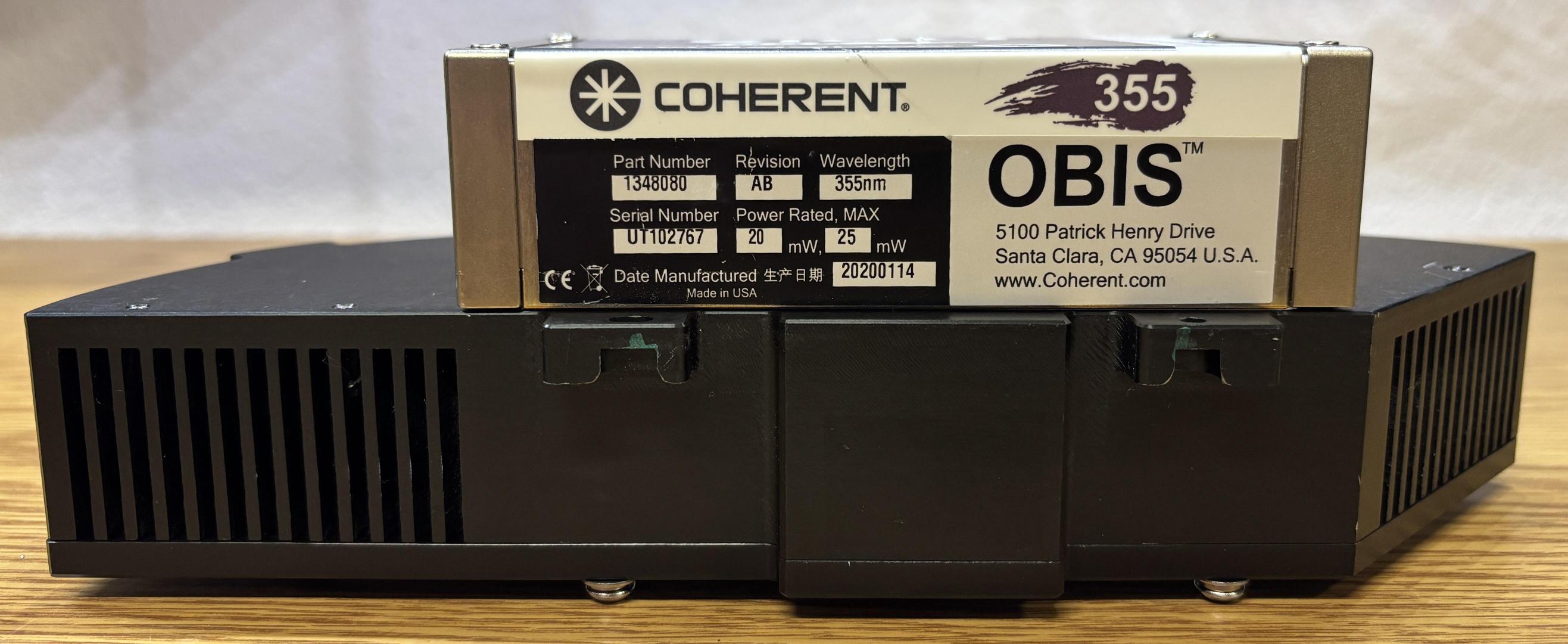
According to the label, this laser system has a nominal output power of 20mW and a maximum output power of 25mW. The software reports a nominal output power of 15mW. This laser was manufactured in 2015 and has about 6000 hours.
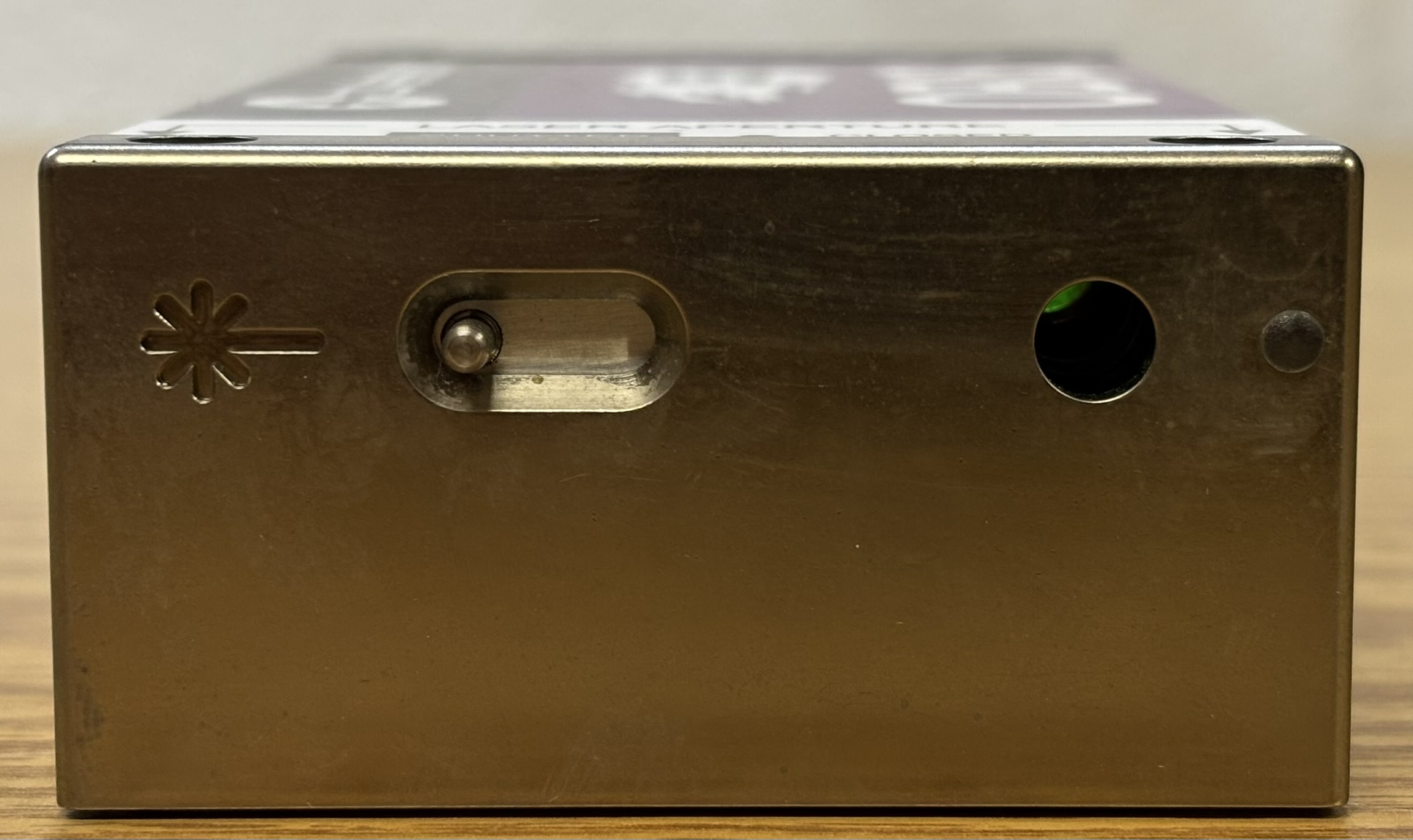
On the front of the laser is the output aperture and mechanical shutter. The laser emission LED is located to the extreme right of the front panel next to the output window.
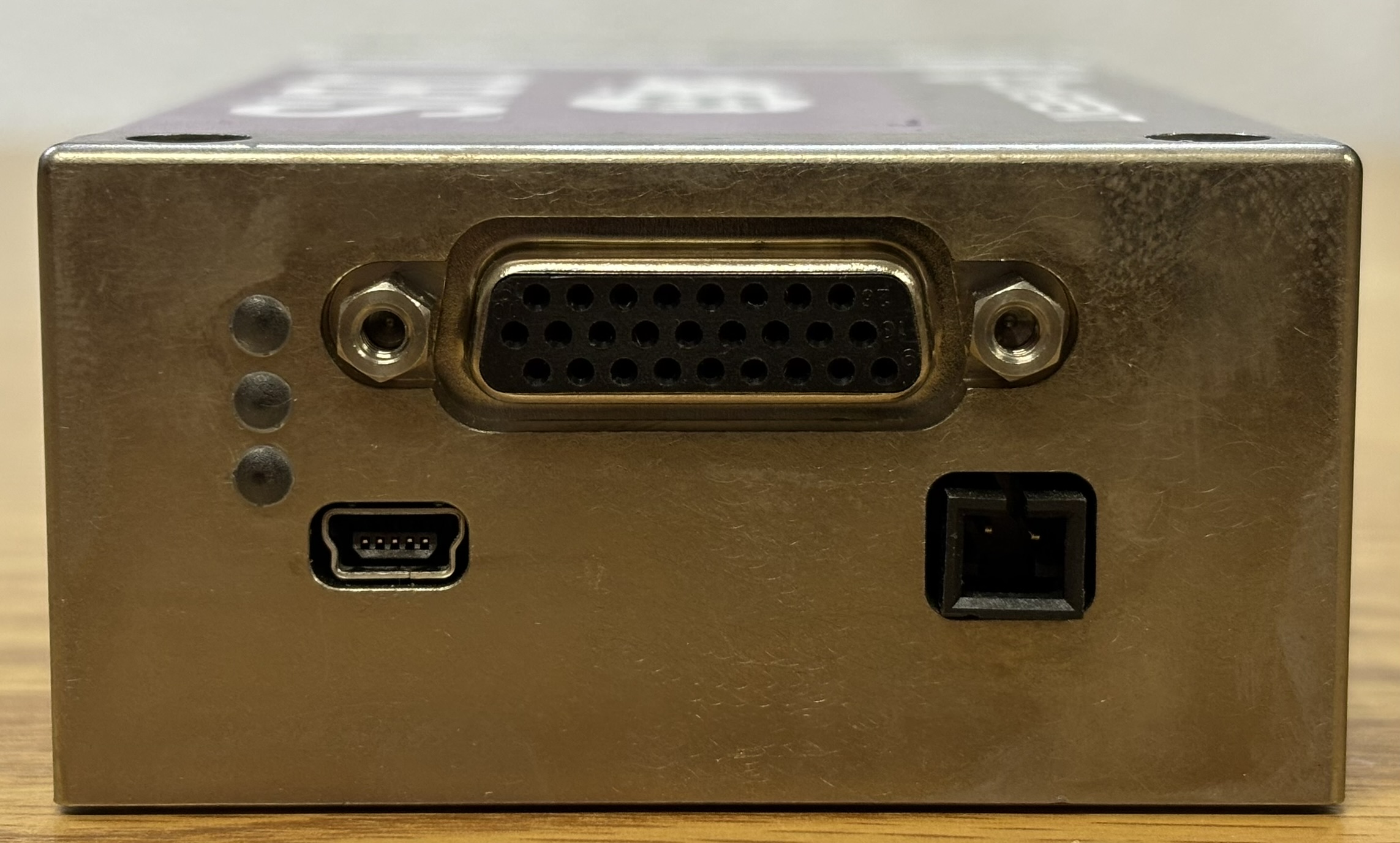
On the back of the laser are 3 status LEDs. The top LED is amber and indicates laser emission. The middle LED is green and indicates system status. The bottom LED is red and illuminates during a fault or when the laser is warming up. The USB Mini-B connector is for the internal USB-to-serial converter and uses drivers supported by Windows 10/11. When the drivers are properly installed, it will show up as a Coherent HOPS device. The black 2-pin connector is for an external cooling fan. Lastly, the DB-26 (HD26) connector is for the DC power input, interlock, enable signal, and the RS-232 serial interface. USB is also available over the 26-pin connector.
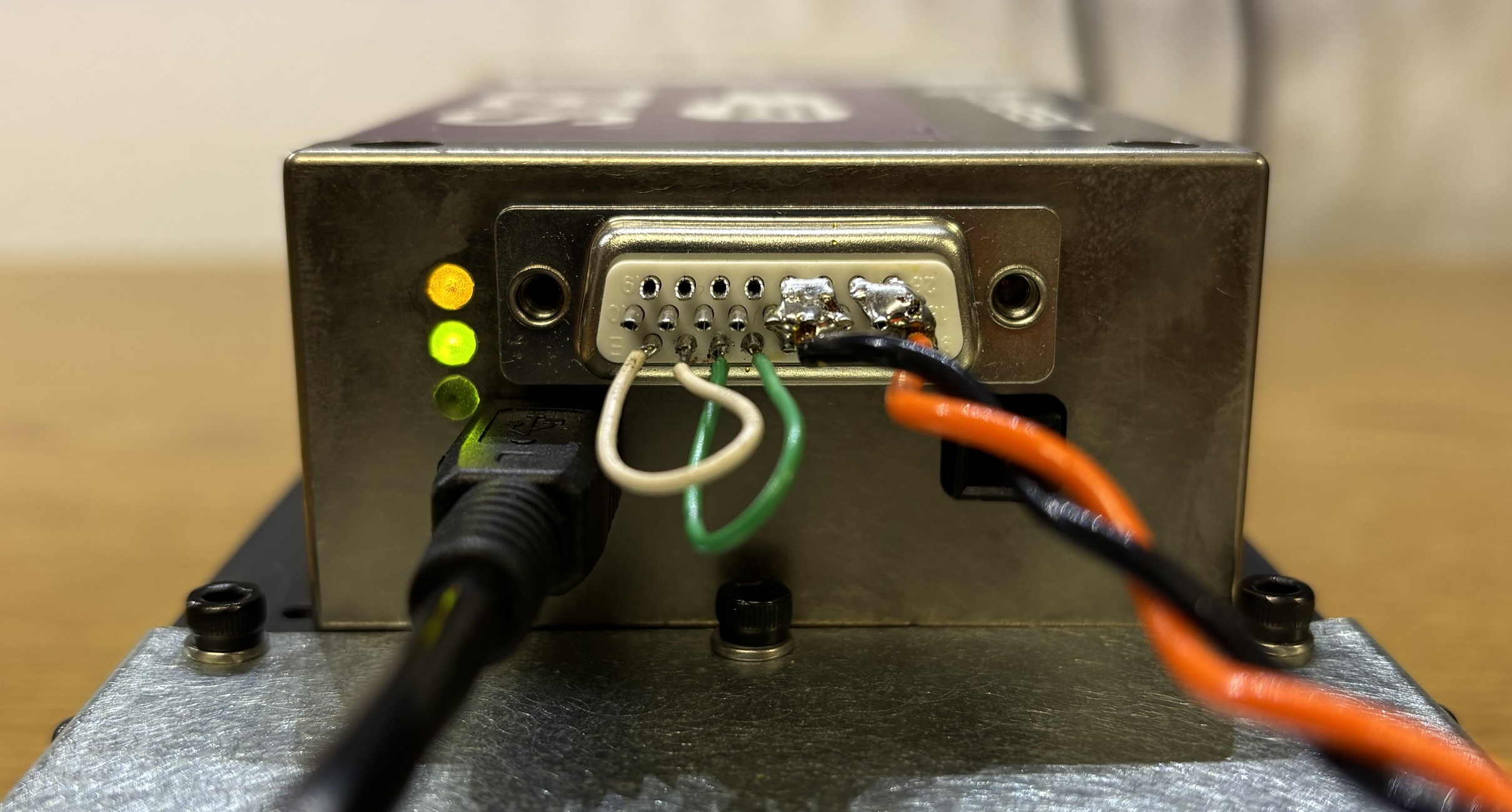
The pin-out for the DB-26 (HD26) connector can be found in the OBIS LG Integrator's Manual but has also been provided below. The OBIS LG requires 24V DC power to operate. Stay as close to 24V DC as possible as undershooting or overshooting the voltage has been known to damage these lasers. The DC power supply must also be capable of providing up to 5 amps of current. We observed this laser drawing peak current during power up, likely while the TEC is cooling the system down to its target target temperature.
| SIGNAL | PINS |
|---|---|
| +24V DC | 7,8,9,17,18,25,26 |
| POWER GROUND | 5,6,14,15,16,23,24 |
| INTERLOCK + | 1 |
| INTERLOCK - | 2 |
| ENABLE + | 3 |
| ENABLE - | 4 |
| USB + | 10 |
| USB - | 11 |
| USB VCC | 22 |
| GND (RS-232/USB) | 21 |
| RS-232 RX | 19 |
| RS-232 TX | 20 |
Establishing serial communication with this laser system is relatively straightforward. The default serial communication parameters are specified below and can also be found in the OBIS LG Integrator's Manual. Command handshake is enabled by default. Refer to the Coherent OBIS LG Laser Systems Integrator's Manual for the full table of serial commands. The USB connection can also be used with regular commands as a USB-to-serial interface. We have a suspicion that the USB interface, when used in conjunction with the Coherent HOPS driver, allows for calibration and advanced manufacturer-only functions.
- BAUD RATE: 115200
- DATA BITS: 8
- PARITY: NONE
- STOP BITS: 1
- FLOW CONTROL: NONE
The wavelength of light produced by this laser system is in the ultraviolet spectrum and is not visible to the human eye. Glow powders or other fluorescent substances/materials are an excellent way to view the output. In the image below, the phosphors contained within paper sticky notes fluoresce a vibrant blue when exposed to the 355nm beam. Use caution when operating lasers that produce light outside of the visible spectrum, as they can still cause permanent eye damage. It's especially dangerous since you cannot easily see the beam.
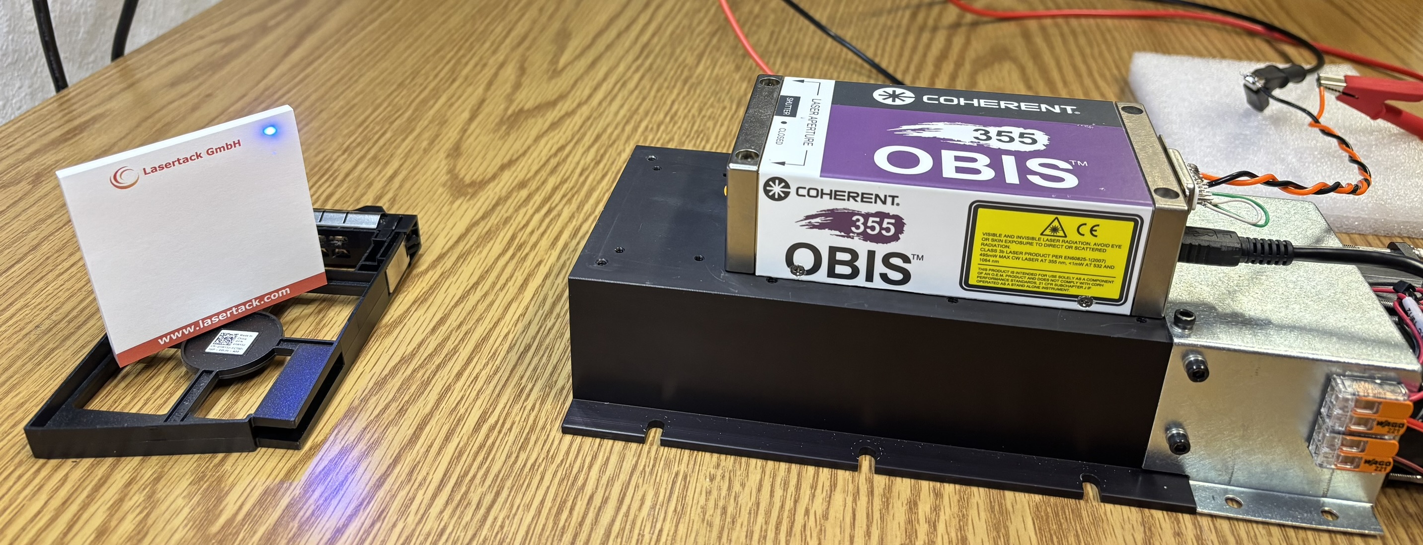
For this portion of the teardown, we disassembled a newer OBIS LG 355-20 from 2020 as it was having some thermal issues and was a better candidate for donating to science. This laser came mounted to an oddly-shaped heatsink and was likely pulled from a piece of scientific equipment.
It was secured to the heatsink with four long bolts that extended entirely through the OBIS chassis to the heatsink. Coherent also recommends thermal pads instead of thermal paste for their lasers. In this case, a very thin and delicate thermal pad was used to ensure adequate heat transfer from the laser head to the heatsink.
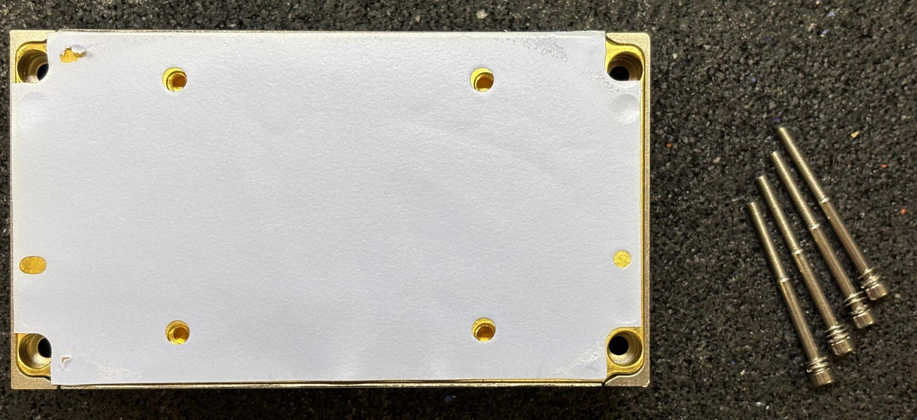
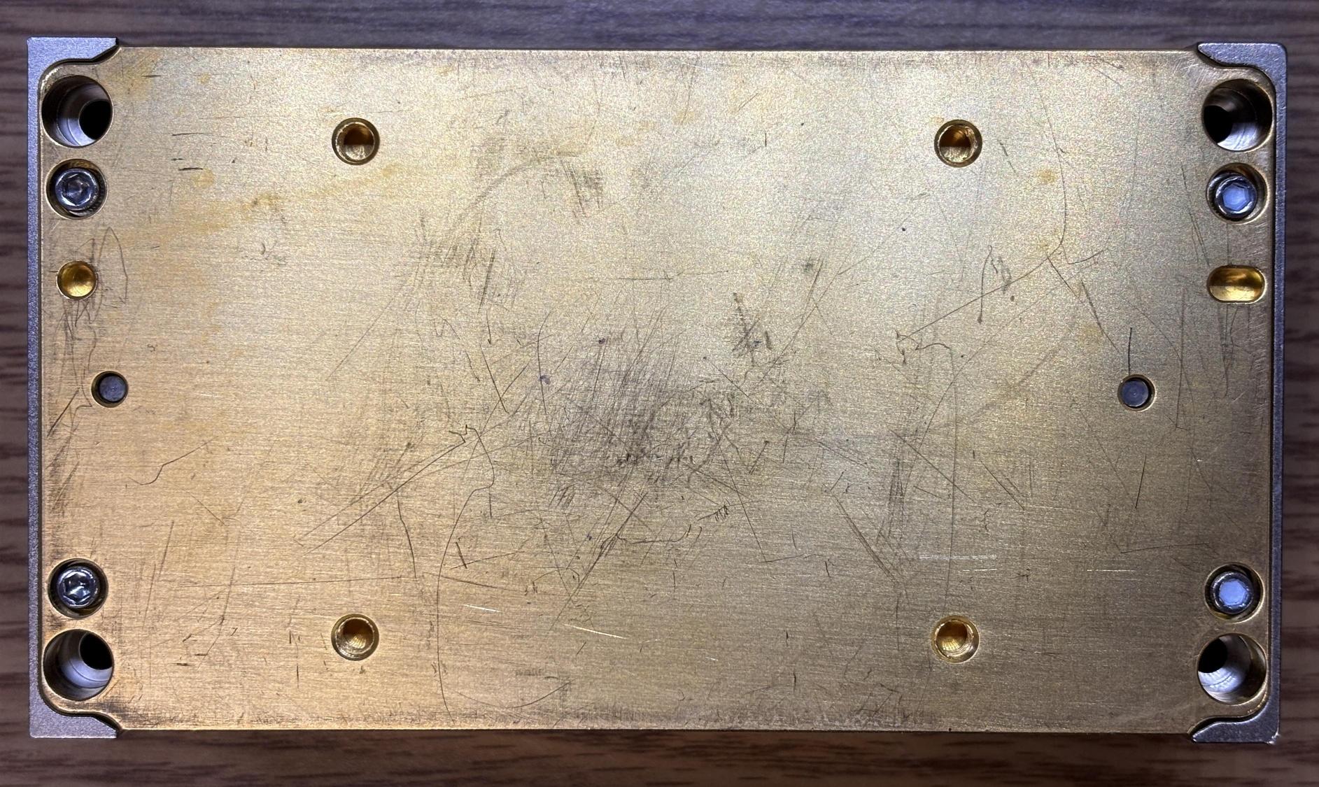
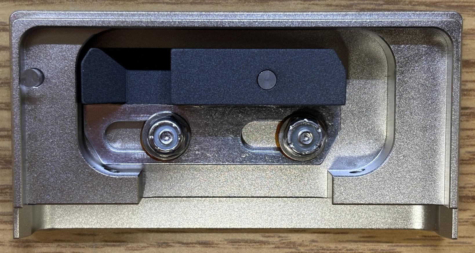
Removing the thermal pad reveals the OBIS thermal baseplate. In addition to the four outer holes for the mounting screws, there are 4 threaded openings closer to the center of the baseplate for mounting the OBIS from the bottom. Lastly, the four hex screws (two on each side) are used to secure the front and back sides of the enclosure to the baseplate.
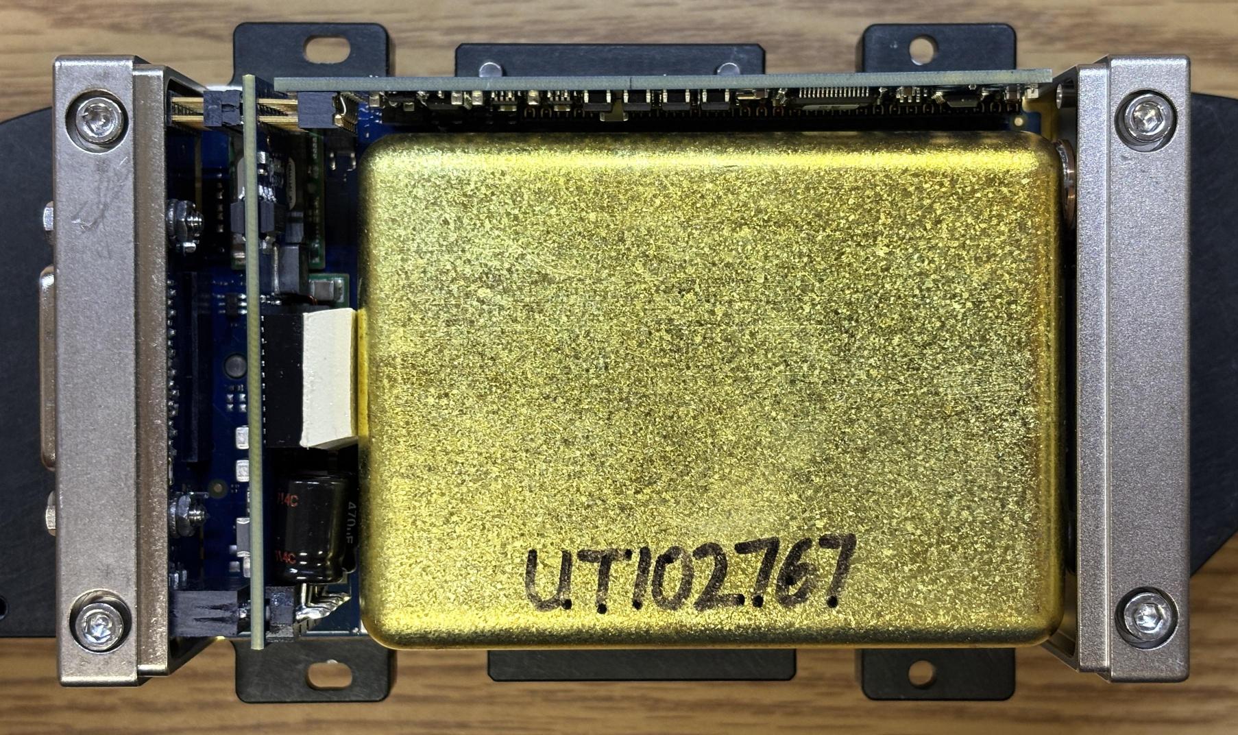
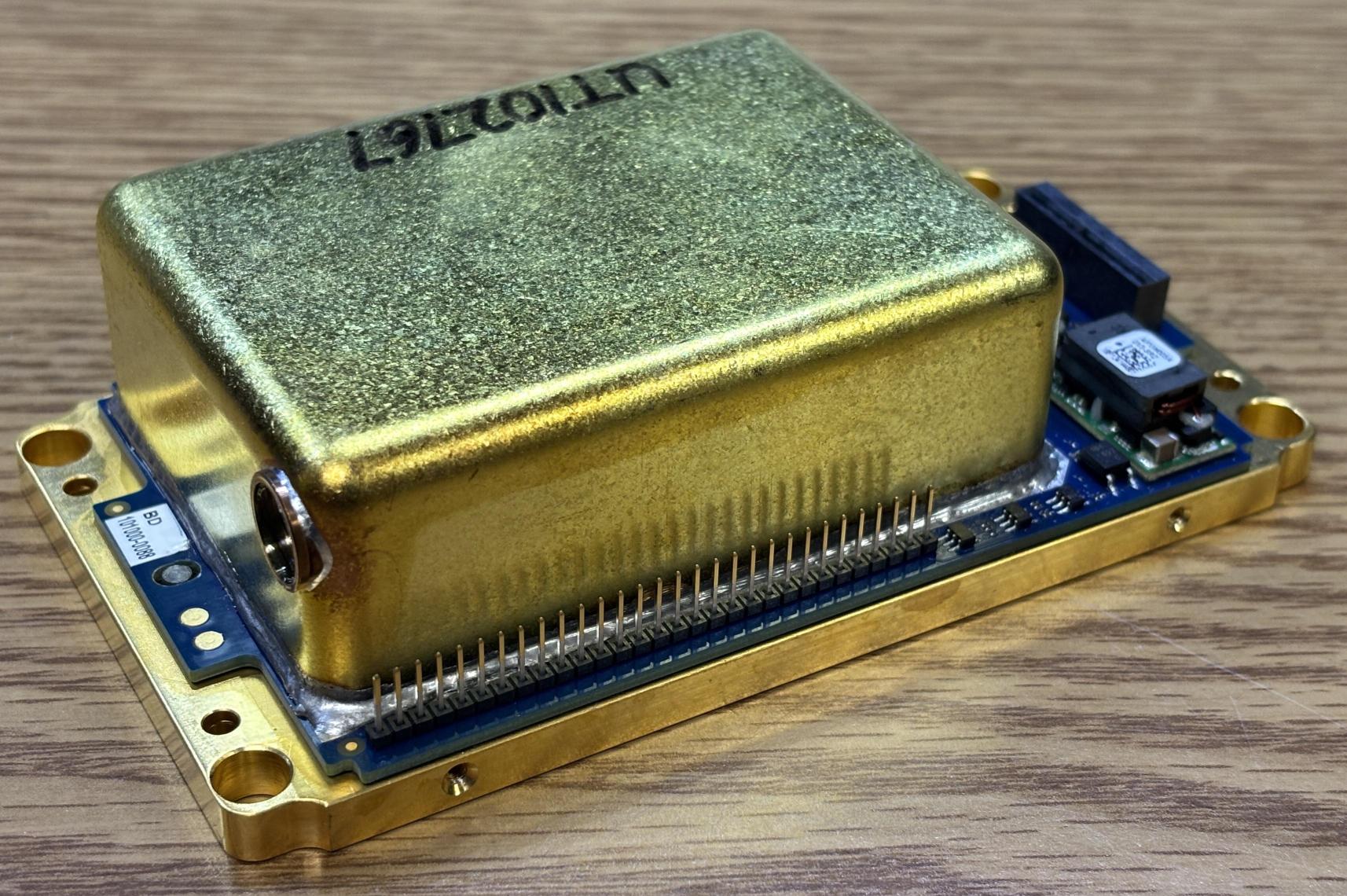
Removing 2 screws on each side of the cover (4 total, hidden under the label) allows the top outer cover to be removed. This reveals the first layer of components, which includes the control boards and sealed optical cavity. The actual laser diode and optical components are located under this metal cover, which is soldered to the bottom circuit board/baseplate.
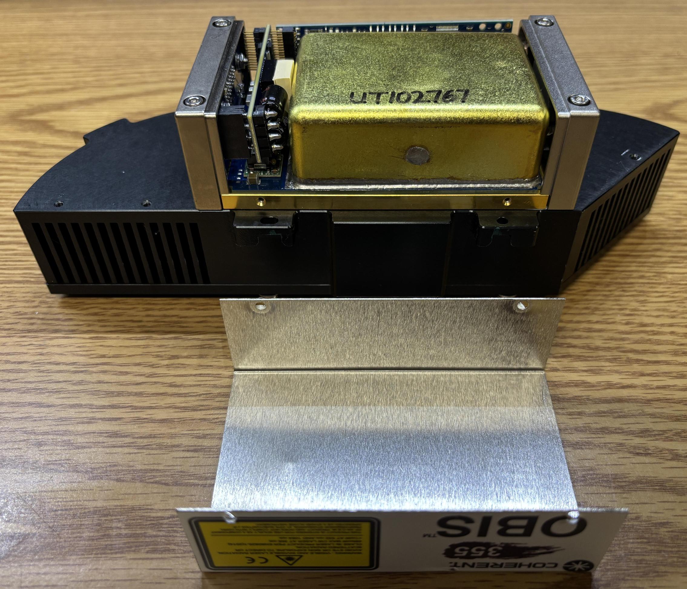
This optical cavity is hermetically sealed and likely filled with an inert gas such as nitrogen. On the front of the sealed enclosure is an optical window that filters out infrared and green wavelengths of laser light, while allowing others to pass though. There are 3 total circuit boards contained within the OBIS LG laser system. The board that runs parallel to the optical cavity is the control and driver board which regulates power to the pump diode and precisely controls the temperature of sensitive optical components contained within the cavity. The boards mounted to the rear of the housing are responsible for power conversion and interfacing/communications. A thick thermal pad is used to dissipate heat from a DC-DC converter.
Removing the mounting screws for the back connector plate allows it, along with the perpendicularly mounted circuit boards, to be removed from the baseplate PCB assembly. Three DC-DC converter modules are now visible on the base PCB. The rear interface, power, and communications PCB has a card edge connector that inserts into a mating socket on the bottom board. The control and driver board has a header that accepts the row of pins that run alongside of the optical cavity.
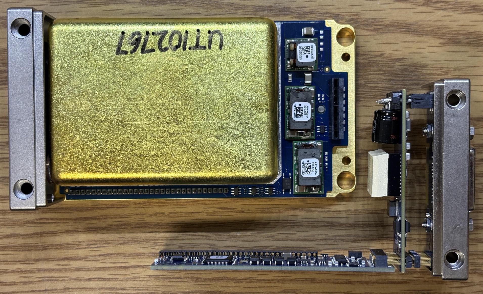
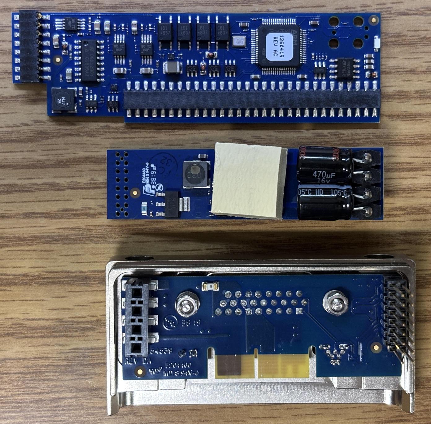
Here are the three boards that make up the OBIS communication interface and control electronics. The top board is the digital board which controls the diode and temperature of the optics. The middle board is just for power conversion. The bottom board is the interface board which breaks out the connections from the DB-26 connector to their respective locations.
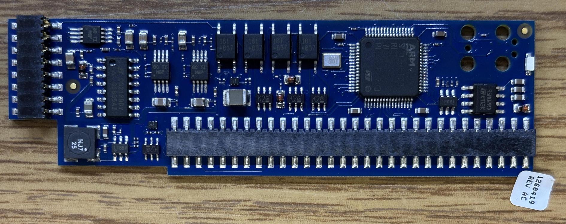
The OBIS digital control board has an STM32 microcontroller which is responsible for running the embedded firmware which controls the laser diode, regulates temperatures, and handles communication with the computer over serial or USB. Additionally, there is a ST M95M02 serial EEPROM which we removed and dumped the contents. Examine the hex dump for yourself by clicking the link below:
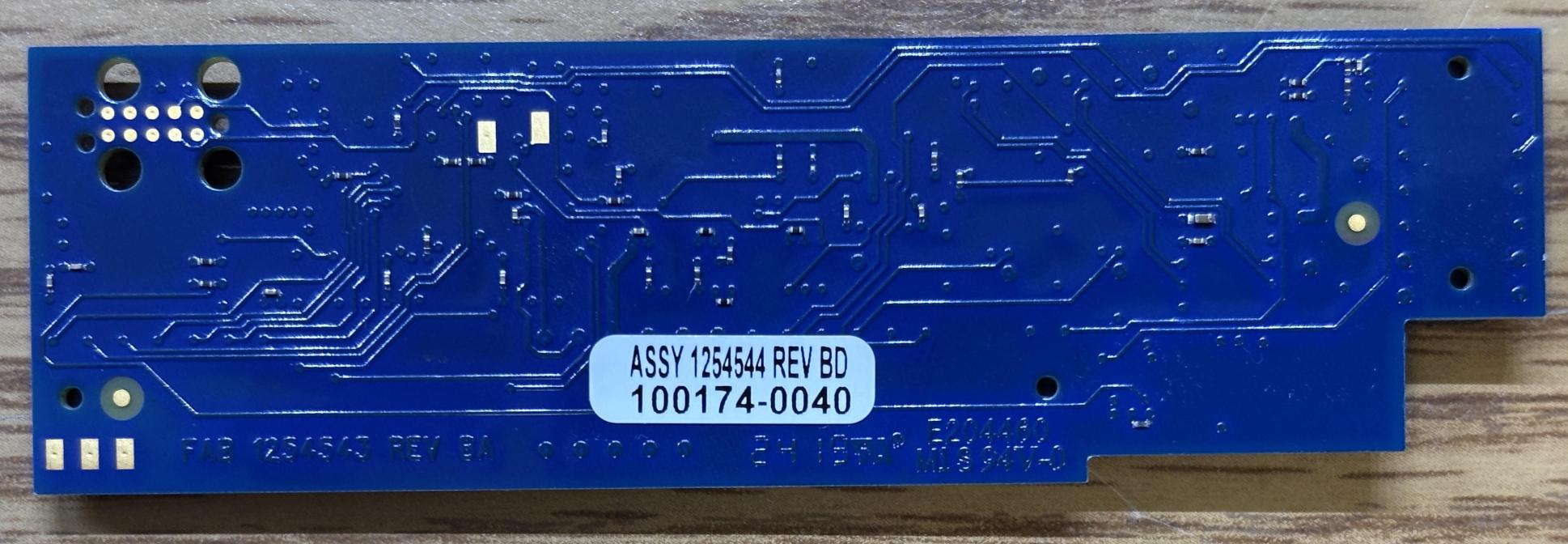
This is the back of the control board, there's not much to see other than an information label and what we presume to be programming pins located on the top left of the board. A test jig would likely clamp on to the board using the four holes and then make contact with the exposed pads.
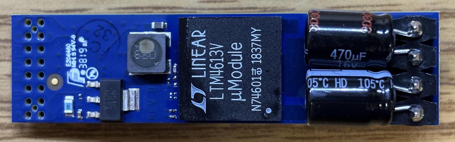
This board is likely responsible for providing regulated DC power for the control electronics within the OBIS. It has a LTM4613 DC/DC μModule Regulator, a LM317A voltage regulator, and some electrolytic capacitors on this side.
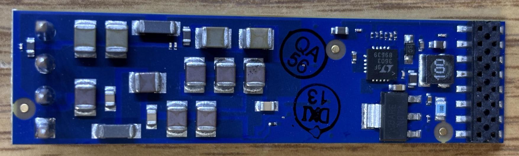
On the other side are several SMD capacitors, another small regulator, and a LTC3603 step-down regulator.
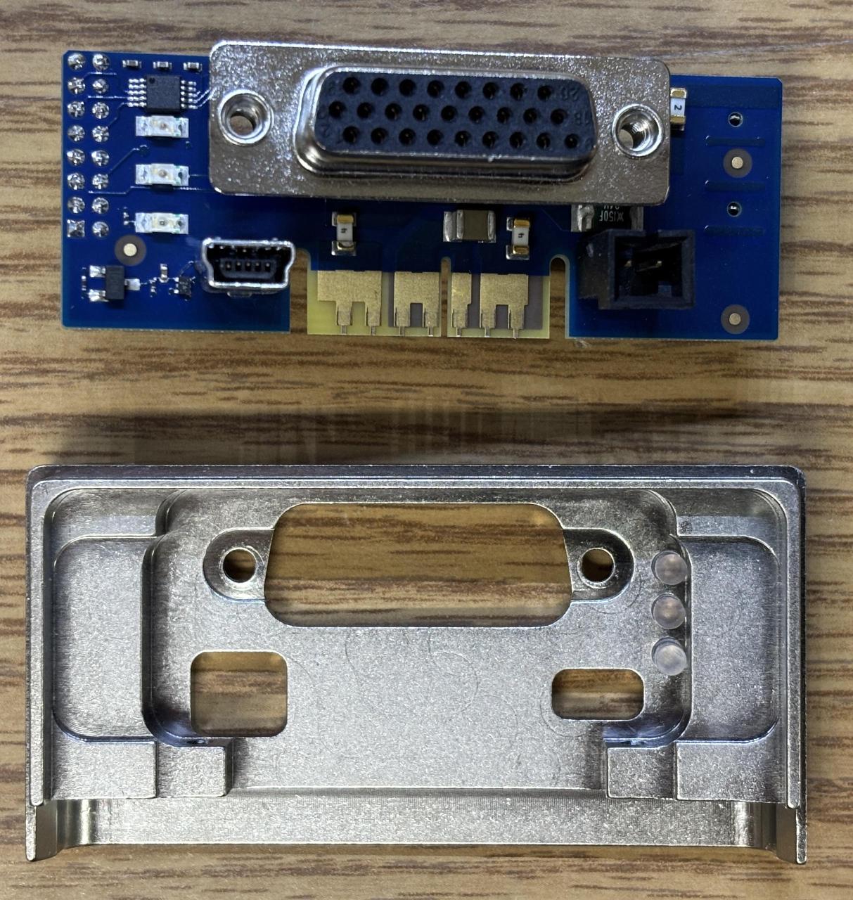
The connections board is pretty straightforward. It breaks out the DB-26 connector, has some LEDs visible externally for status monitoring, the USB connector, fan connector, and some fuses. It connects directly to the power conversion board through a high current pin header and to the digital board via a dual-row pin header.
At this point, we also removed the front plate which includes the shutter.
Here is the bare assembly with the digital boards and front and back covers removed.
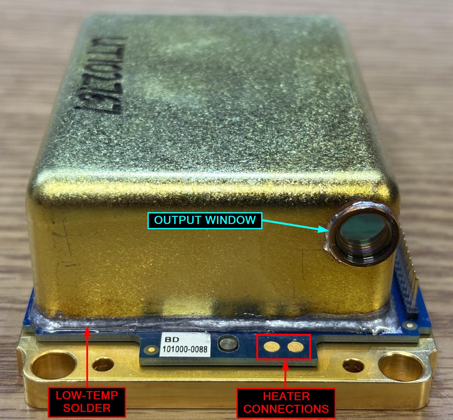
This is the front of the resonant cavity. This cover is soldered to the baseplate with some low-temp solder. Previously, we thought a heat gun was required to heat up and remove this cover, but it turns out there is an easier way. The two pads located on the PCB section below the output window are actually connected to a resistive heating element that is directly below the perimeter of the soldered cover. When measured, the resistance of the heater was 2 ohms. Even though we did not know the exact parameters of the heater, we could make educated guesses based off the size and resistance.
We soldered some wires to these pads and started applying DC power at a low voltage and current. We slowly ramped it up as the top cover began to get warm. After about 5 minutes running the heater at 11.5V DC with a 4.5A current limit, the solder around the perimeter of the cover began to melt. Shortly after, we were able to lift the cover straight off. This built-in heater was completely undocumented, but drastically improves the repairability of the OBIS. Based on further testing, we believe running the heater at 12V DC with a 5A current limit for 5 minutes or less should be sufficient to melt the solder. The same process can be used to re-install the cover. With the cover removed, we can now see further into the resonant cavity. There is a small desiccant pouch located within a slot on the cover.
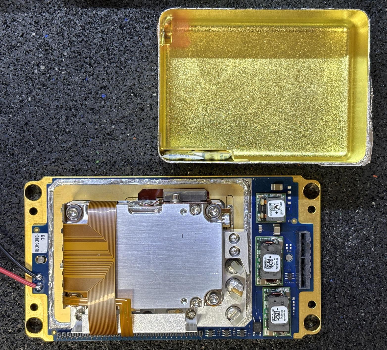
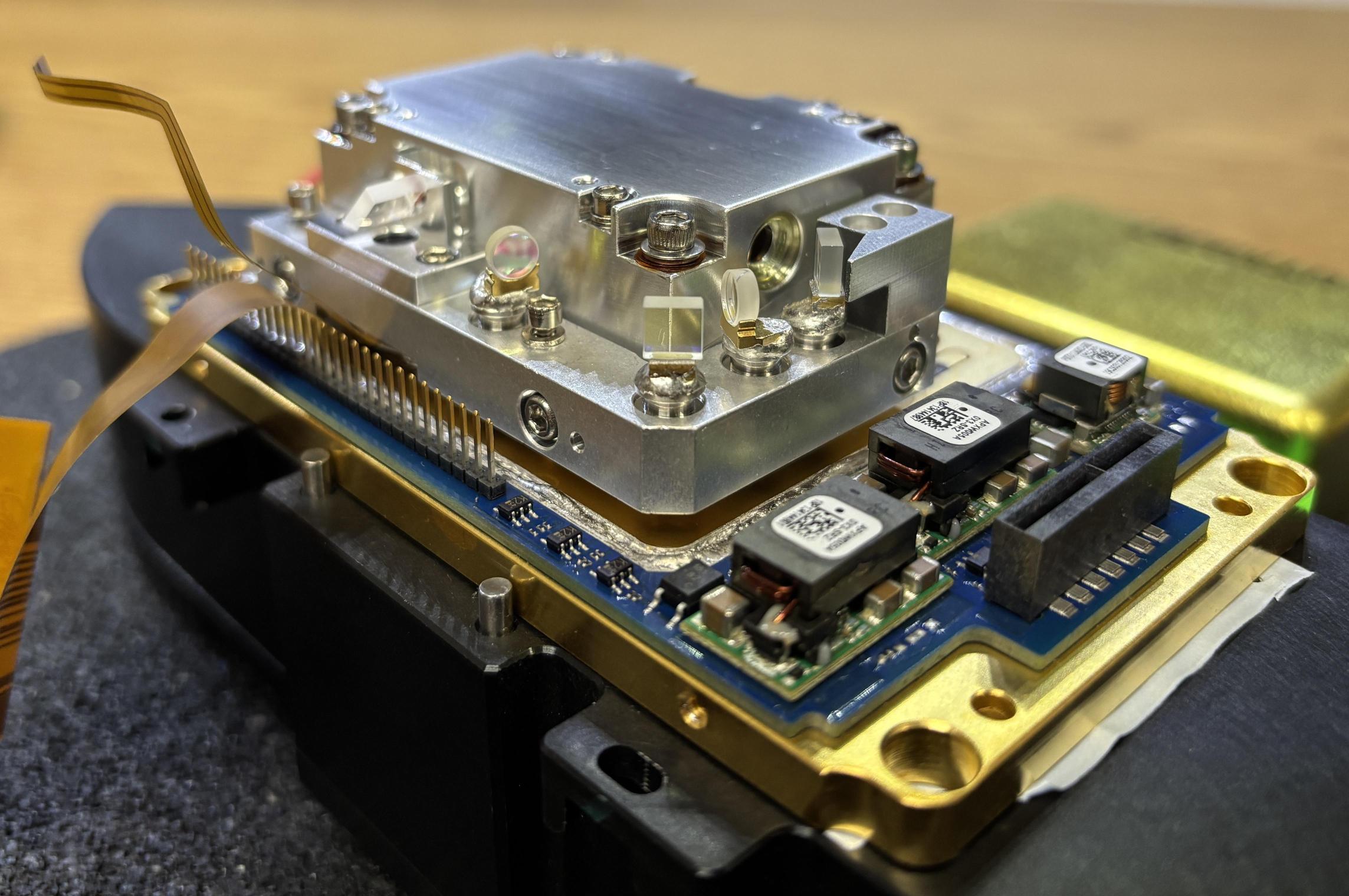
Under the hermetically sealed cover are the actual optical components and pump diode. The majority of the components are further protected by another aluminum enclosure. Some filtering optics and lenses are visible at this point. Take note of the flat-flex ribbon cable that connects the diode and temperature control/sensing components to the bottom circuit board.
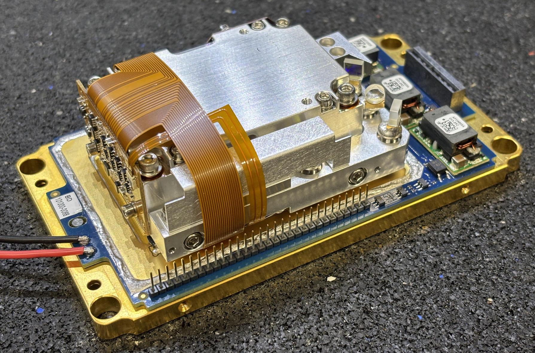
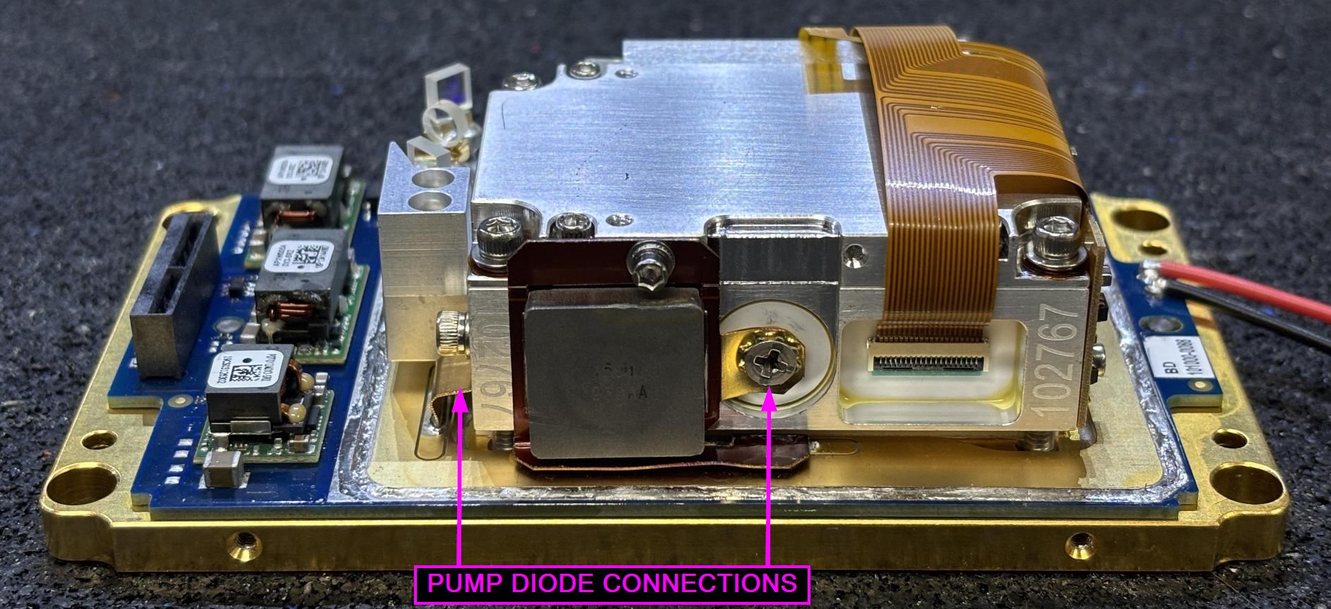
This inner resonant cavity and optics platform is mounted on a TEC, and secured to the baseplate by bolts that extend through the top corners of the aluminum enclosure. This side view exposes the pump diode connections and the flat-flex ribbon cable which connects to a ceramic board that feeds the connections through to the inside of this enclosure.
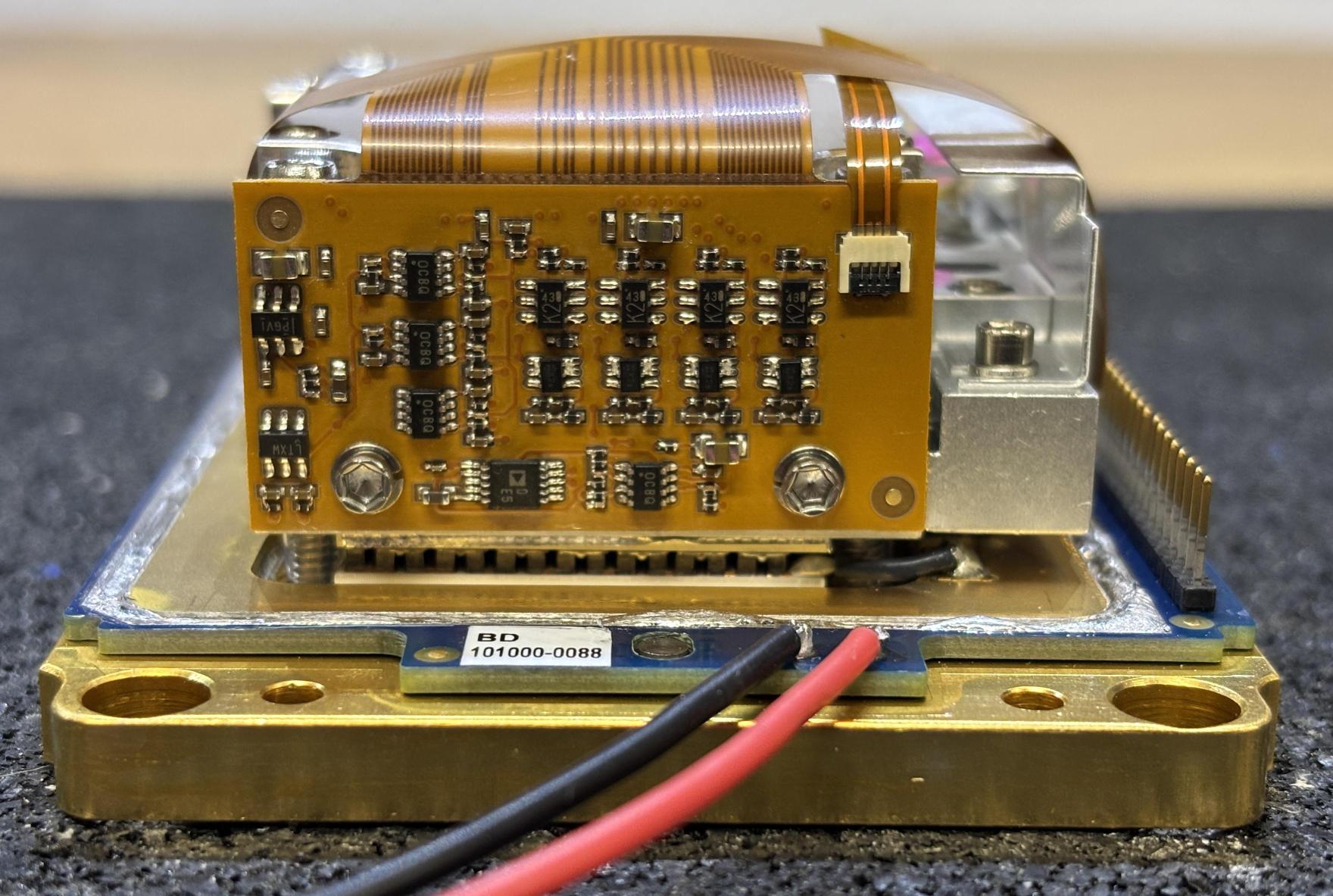
The flat-flex ribbon leads to a small PCB mounted to the side of the inner cavity. On the PCB are several operational amplifiers and MOSFETS, and one additional connection for an optical pick-off located outside of the inner cavity. The other side of the ribbon terminates into the baseplate for the single-row pin header that inserts into the socket on the digital control board.
This picture of the back of the inner assembly shows the cavity output window, one pump diode high-current connection, and some of the beam forming and filtering optics. These optics appear to be mounted on small pedestals of solder. This is likely a low-temp solder that can be heated either externally or internally with a small heater to melt the solder and permit alignment of the optics. Once alignment is complete, heat is removed and the solder solidifies, locking the optics in place.
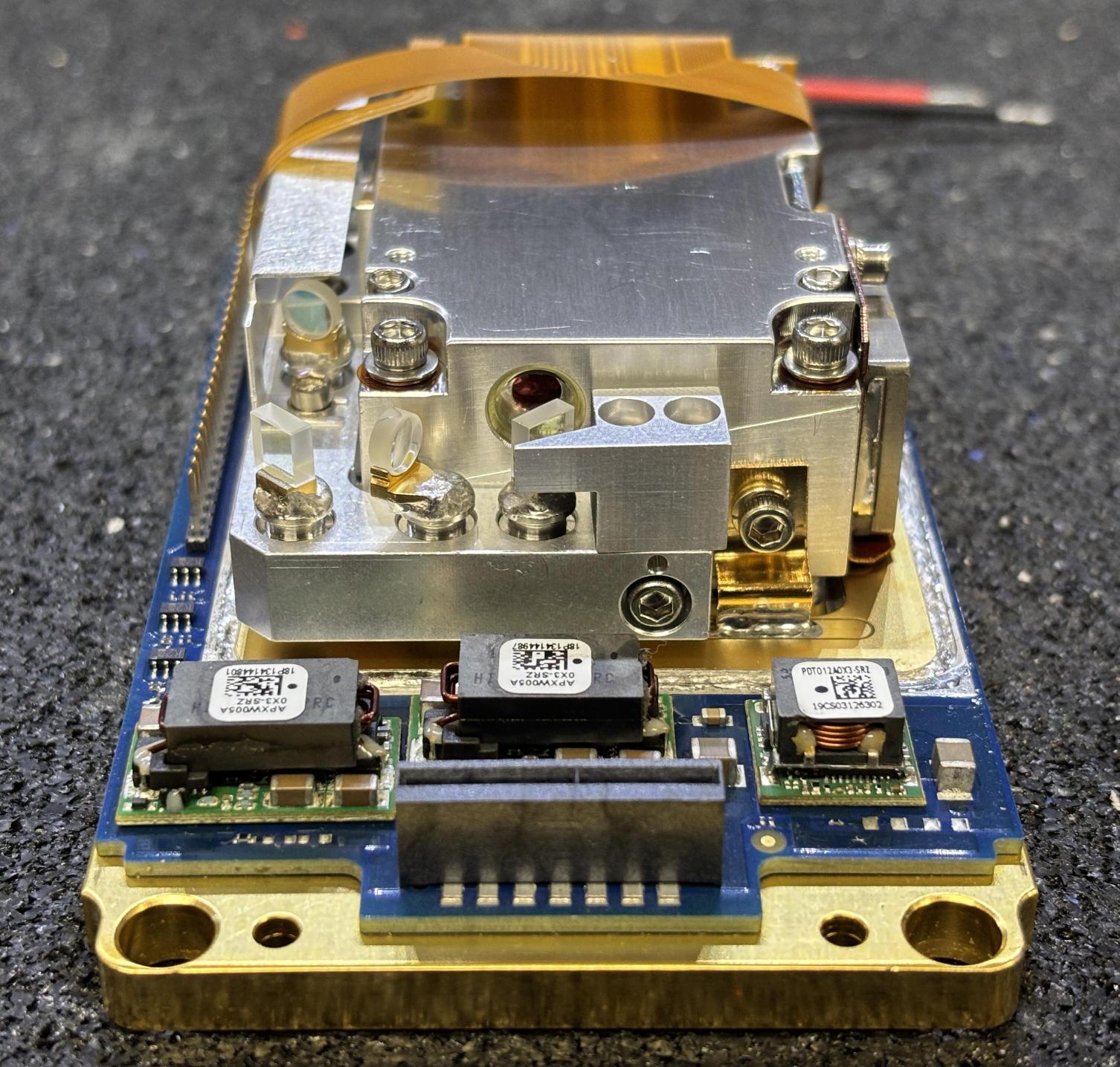
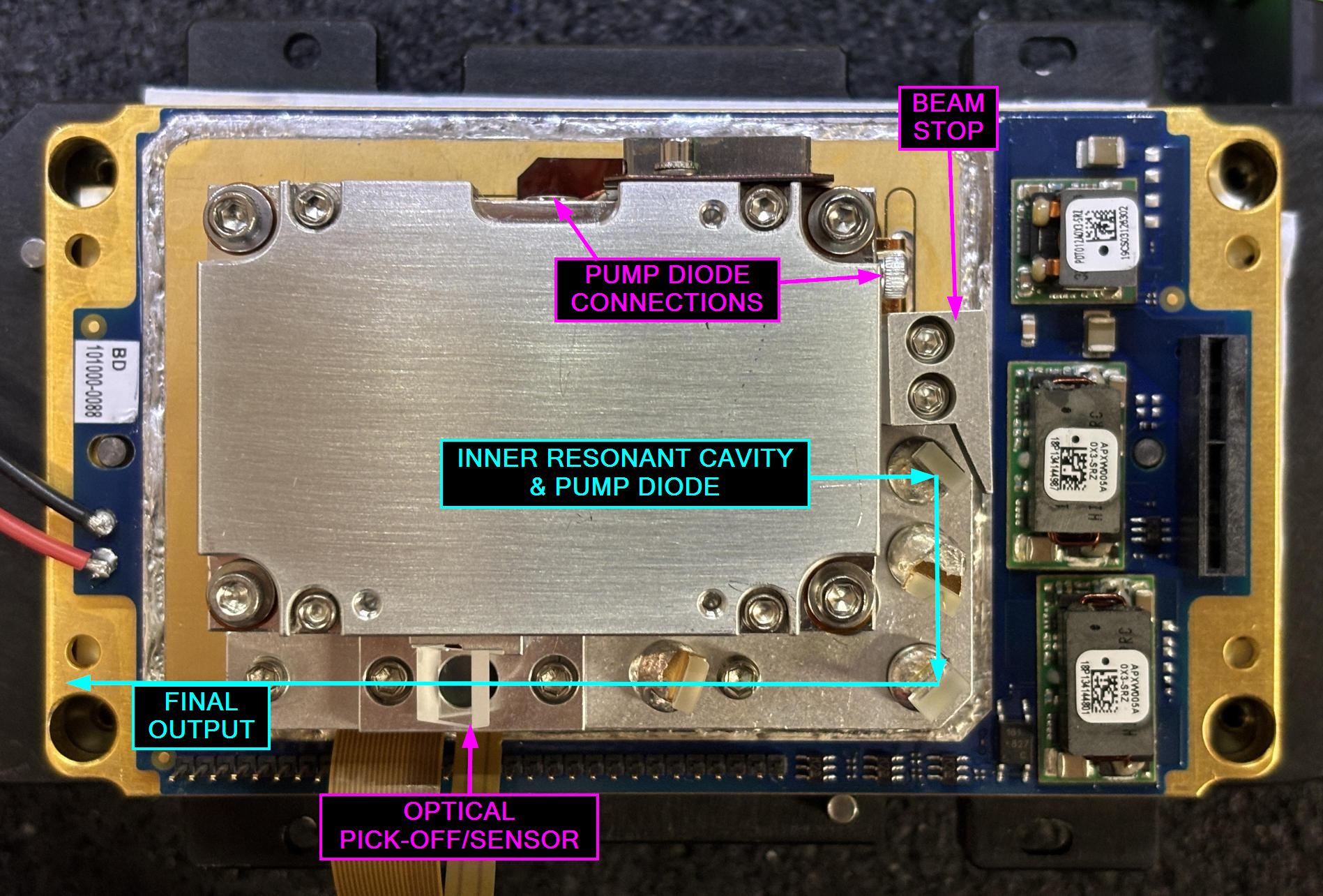
With the PCB removed, flat-flex cleared out of the way, and a small protective bracket removed, we can get a better view of the optics located outside of the resonant cavity.
Here is an annotated diagram of the beam path external to the resonant cavity. The beam path is outlined in cyan and other notable components are highlighted in magenta. Laser light exits the cavity, makes a right angle, passes through an optic, makes another right angle, passes through additional filtering optics, past an optical pick-off or sensor, and then finally through the output window (on the top cover that was removed earlier).
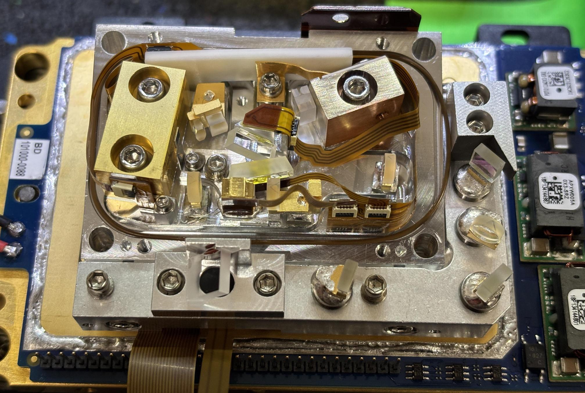
All eight screws on the top (four to clamp the two halves together, four to secure the assembly to the baseplate) must be removed in order to open the inner resonant cavity. It was sealed with an o-ring and required delicate but firm pressure to get the top cover off without ripping the entire assembly off the TEC. Finally, we get our view of the inner resonant cavity of the OBIS.
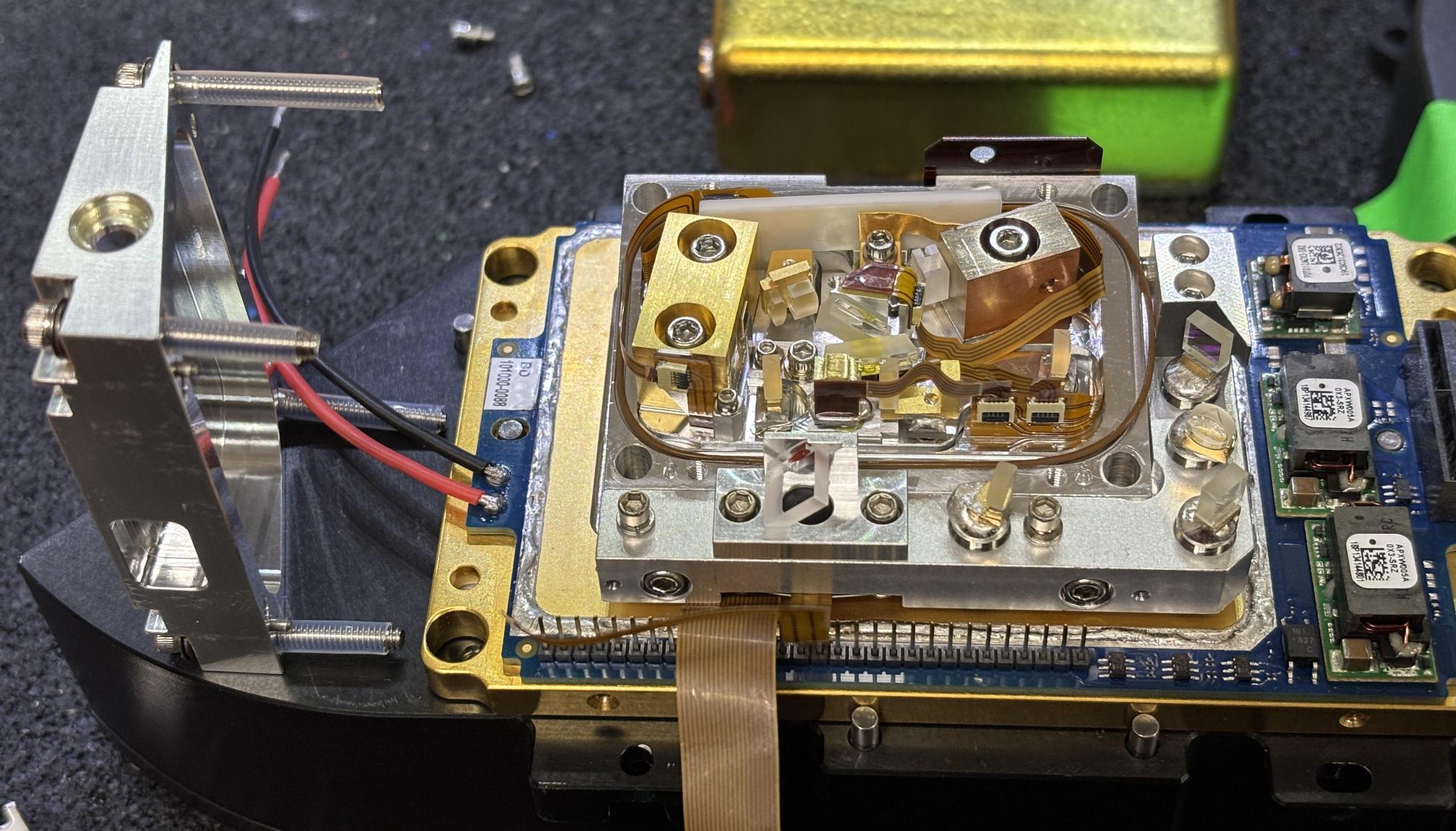
This resonant cavity is nothing short of a work of art, considering the precision required to mount and align all of the optics within, let alone perfectly manage their temperature during operation to facilitate harmonic generation.
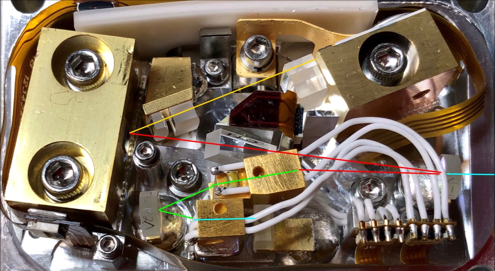
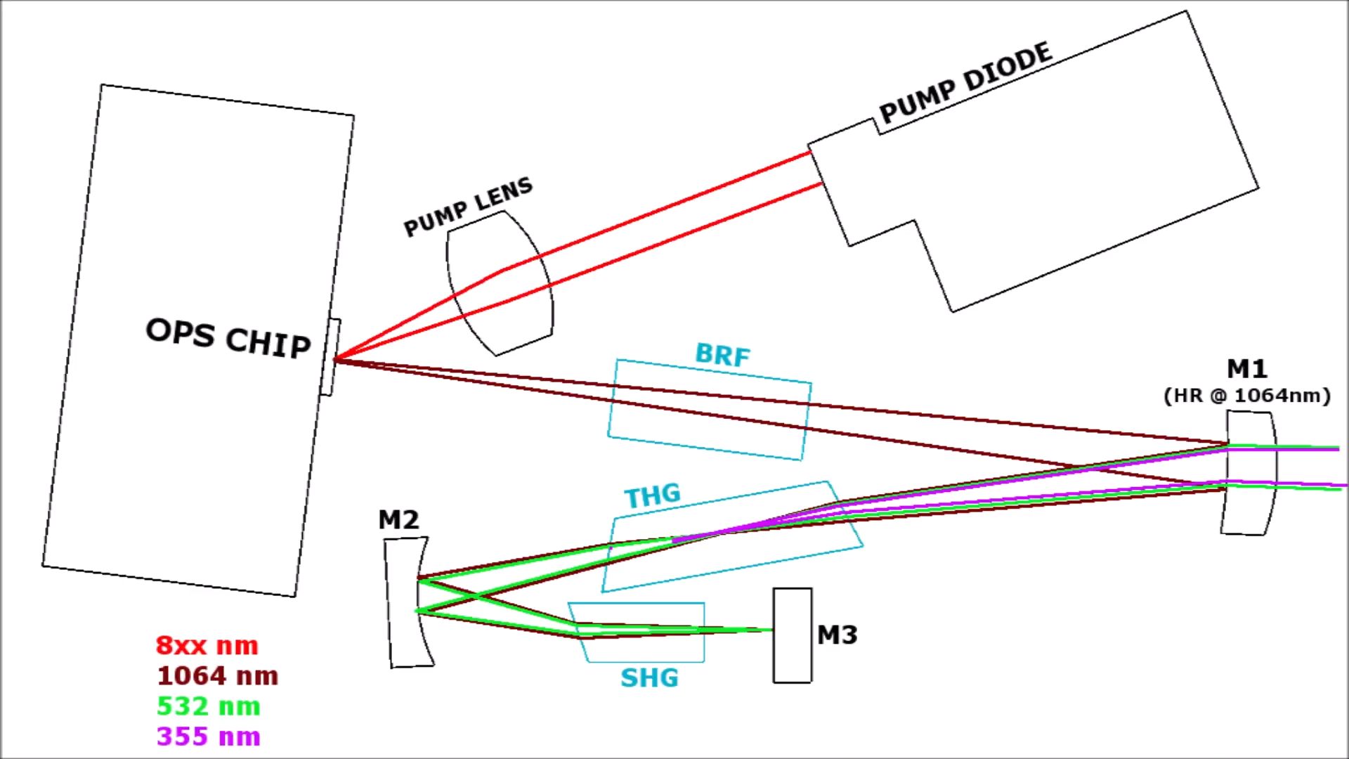
Below is an image of the inner optical cavity from an older OBIS variant. The colored lines correspond with the beam path. Since this is an OPSL laser, light emitted from the pump diode is filtered through a lens and then reflects off an OPS chip, converting the wavelength. The wavelength is further converted by second and third harmonic generation optics that follow. It is worth noting that both 532nm and 355nm light is produced by this optical assembly. However, the 532nm (green) light is filtered out before it leaves the laser head. This results in 355nm being the only wavelength emitted, which is the intent of this OBIS LG model.
Here is an annotated image that describes the beam path of the OBIS LG 355nm laser. Thank you, Patrick, for providing this image to us.
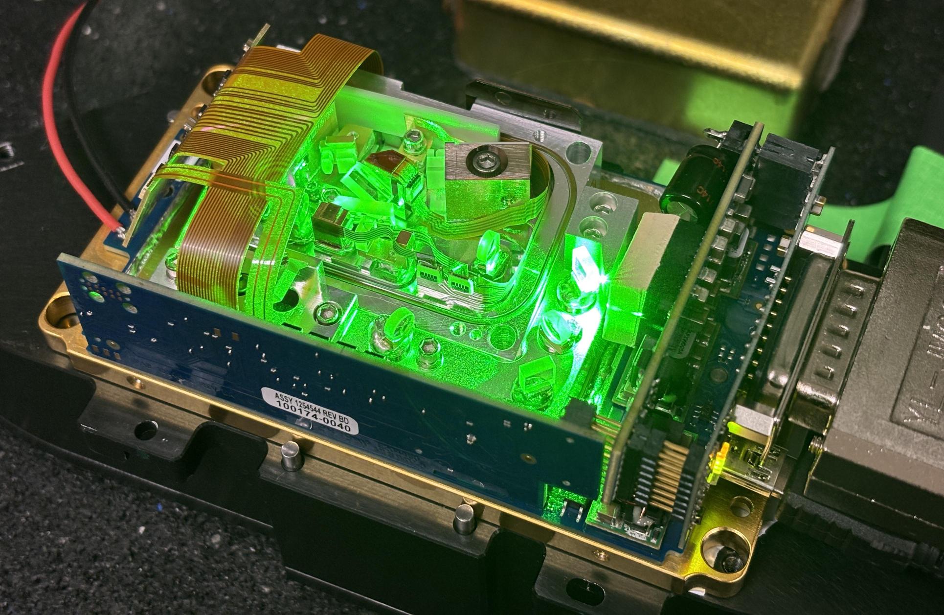
Even though this unit was being donated to science, it was still functional and capable of lasing. Below is an image of it running with all covers removed, exposing the innermost resonant cavity and optics. Even though the OBIS LG 355-20 is not a green laser, it produces a spectacular amount of 532nm green light internally.
Please check out Patrick's detailed video about this laser. To learn more about OPSL lasers and the OBIS LG, visit the links below.