The NovaLum 1200 is a complete RGB laser system from NECSEL (now USHIO). Within the laser head are three individual laser diodes: red (638 nm), green (525 nm), and blue (465 nm). A knife-edge array is used to combine the beams and direct them to the output aperture, which accepts a fiber with a SMA connector. The whole module has a maximum output power of around 5 watts when all diodes are operated at maximum power. This system uses VCSEL (vertical cavity surface emitting laser) diodes, which appear to be NECSEL's specialty. Additionally, the three colors can be independently modulated and adjusted by the digital driver to produce essentially any color at varying intensities. Use cases for an RGB laser like the NovaLum 1200 include laser light shows and remote source lighting.
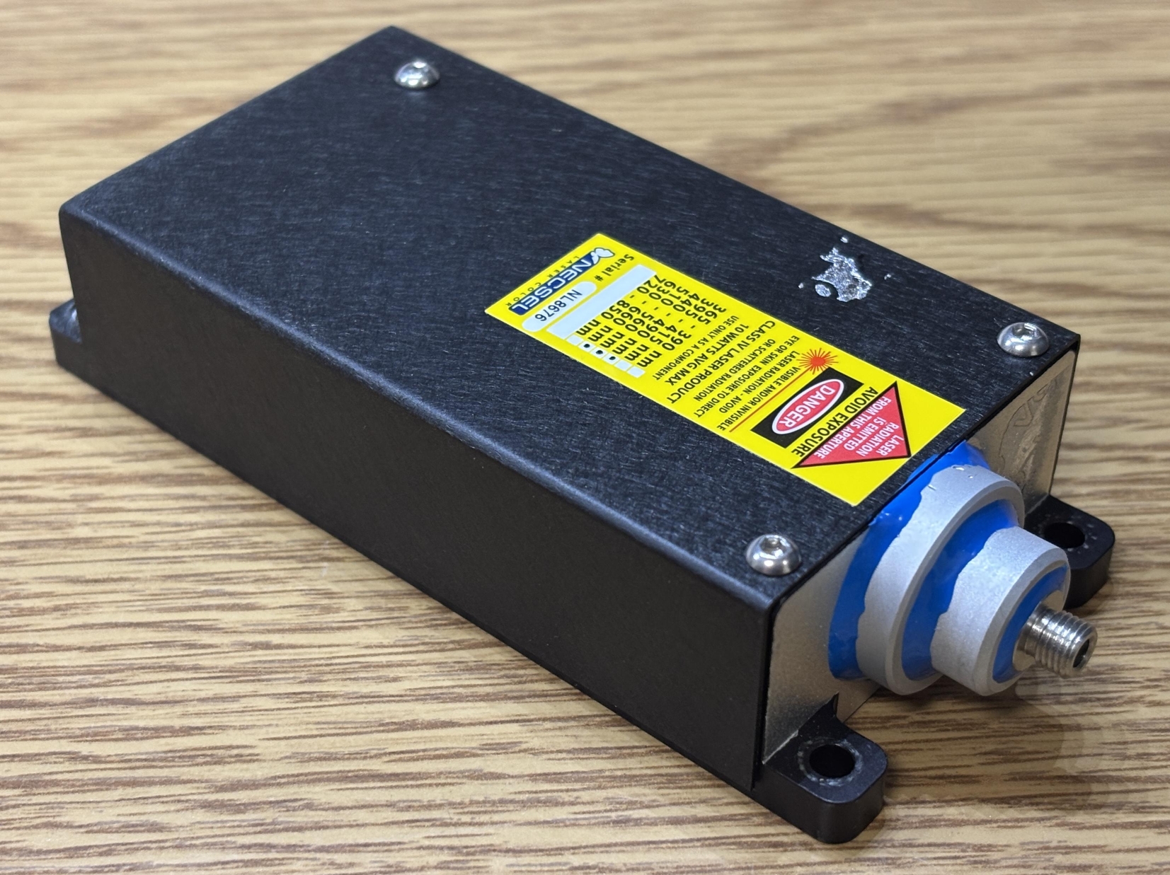
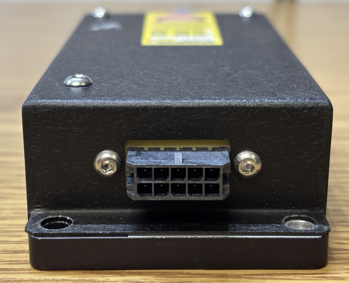
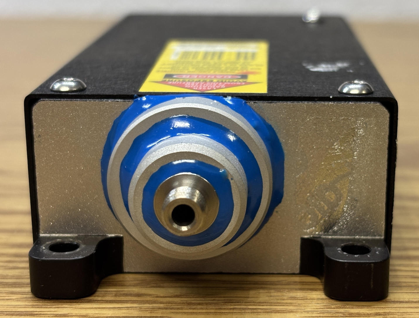
On the back of the laser head is a 10-pin Molex micro-fit connector. This serves as the laser head connection and directly passes the diode power pins along with a thermistor to the driver board. A pin-out for the connector can be found on the manufacturer's datasheet linked at the bottom of this page. On the front of the laser head is the output aperture. It's an interesting arrangement of aluminum rings stacked on top of each other and glued in place. It's completed with a male SMA connector which allows a fiber to be attached. A custom ThorLabs fiber (FT400EMT) was included with this laser system.
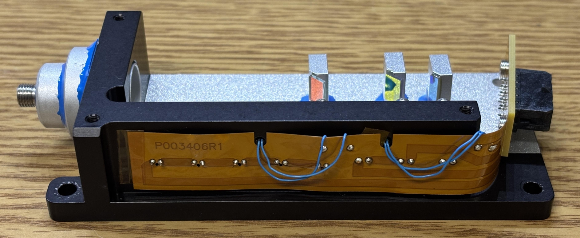
Removing the three hex screws on the top and two on the back on either side of the Molex connector allows the top cover to be lifted away. Inside the laser head are the three VCSEL laser diodes mounted to the side of the casing. There are many more unpopulated openings, which indicates that other models could include more diodes. Three mirror mounts are glued to the bottom surface and hold the knife-edge mirrors in precisely the right position to allow the beams to combine and be directed out of the aperture. It is likely that the mounts were adjusted while the laser was on and the glue was allowed to harden only after alignment was completed. One downside of this approach is that it's difficult to correct the alignment later if needed. A flat-flex PCB runs the whole length of the case and serves as the power connection backplane for the laser diodes. The thin blue wires are for the thermistors pressed into the aluminum frame, near the diodes.
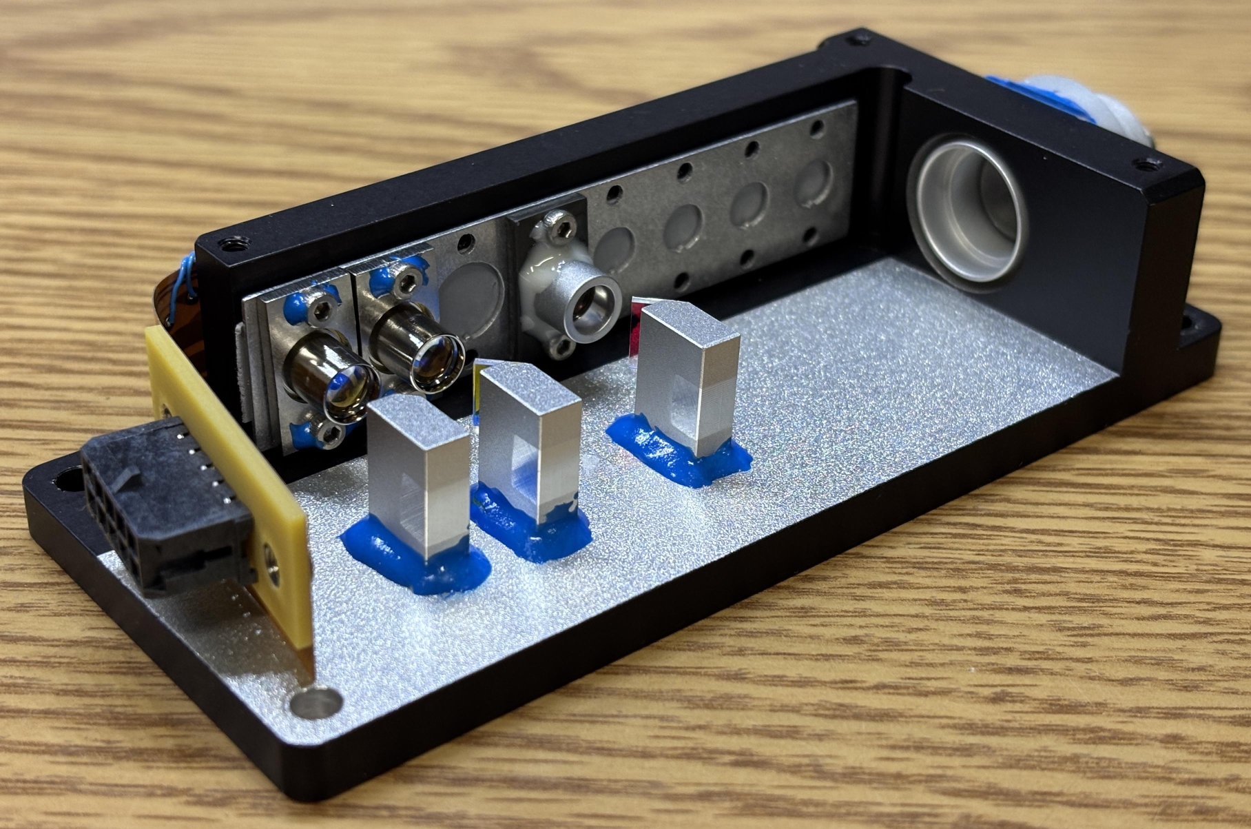
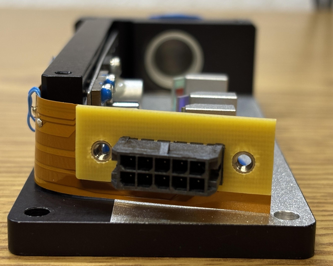
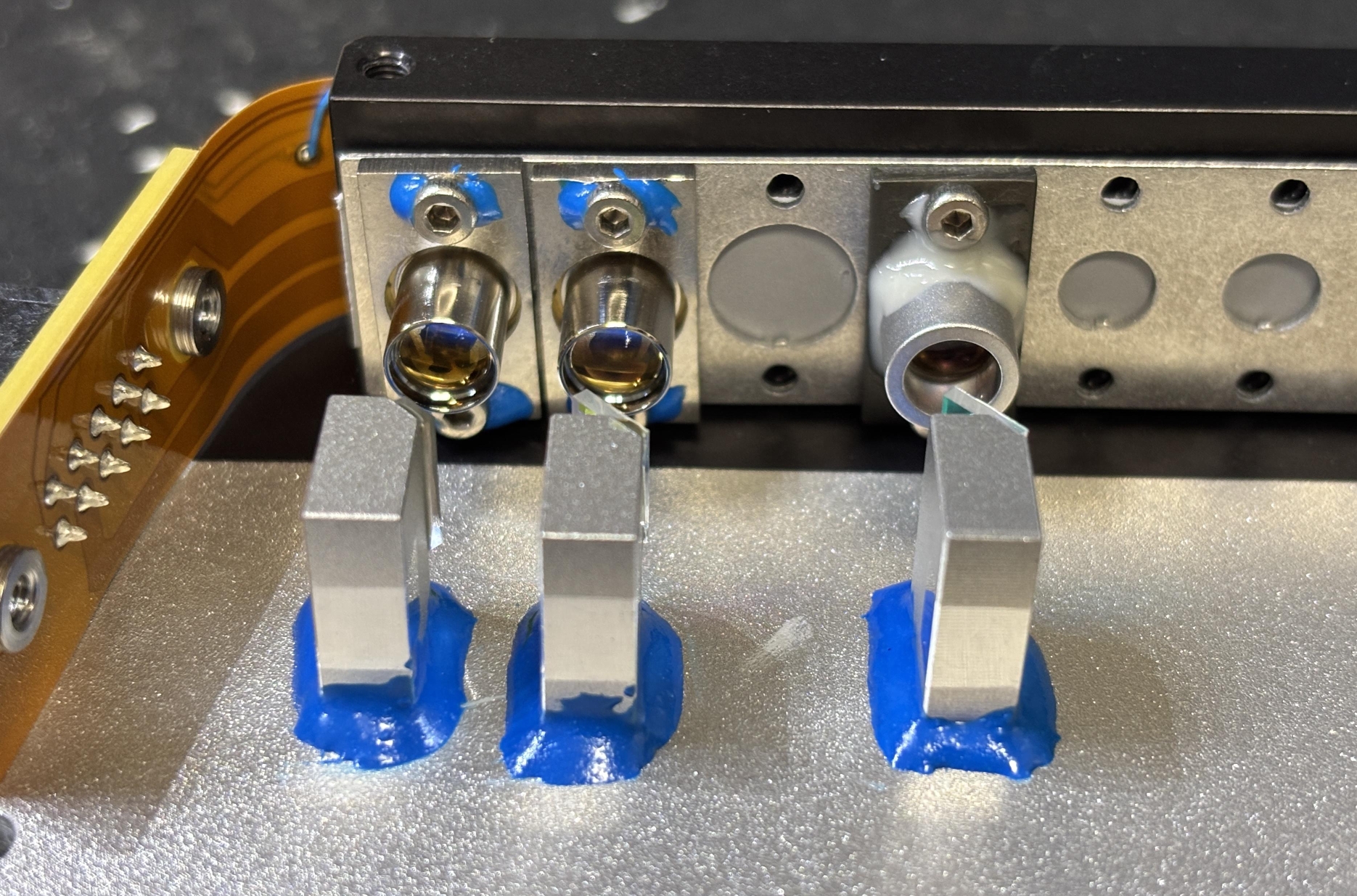
The Molex connector is soldered directly to the flat-flex along with a small piece of hard PCB. This gets secured to the aluminum casing once the screws are installed. Here is another angle that showcases the VCSEL laser diodes with integrated lenses as well as the knife-edge mirror and mount arrangement.
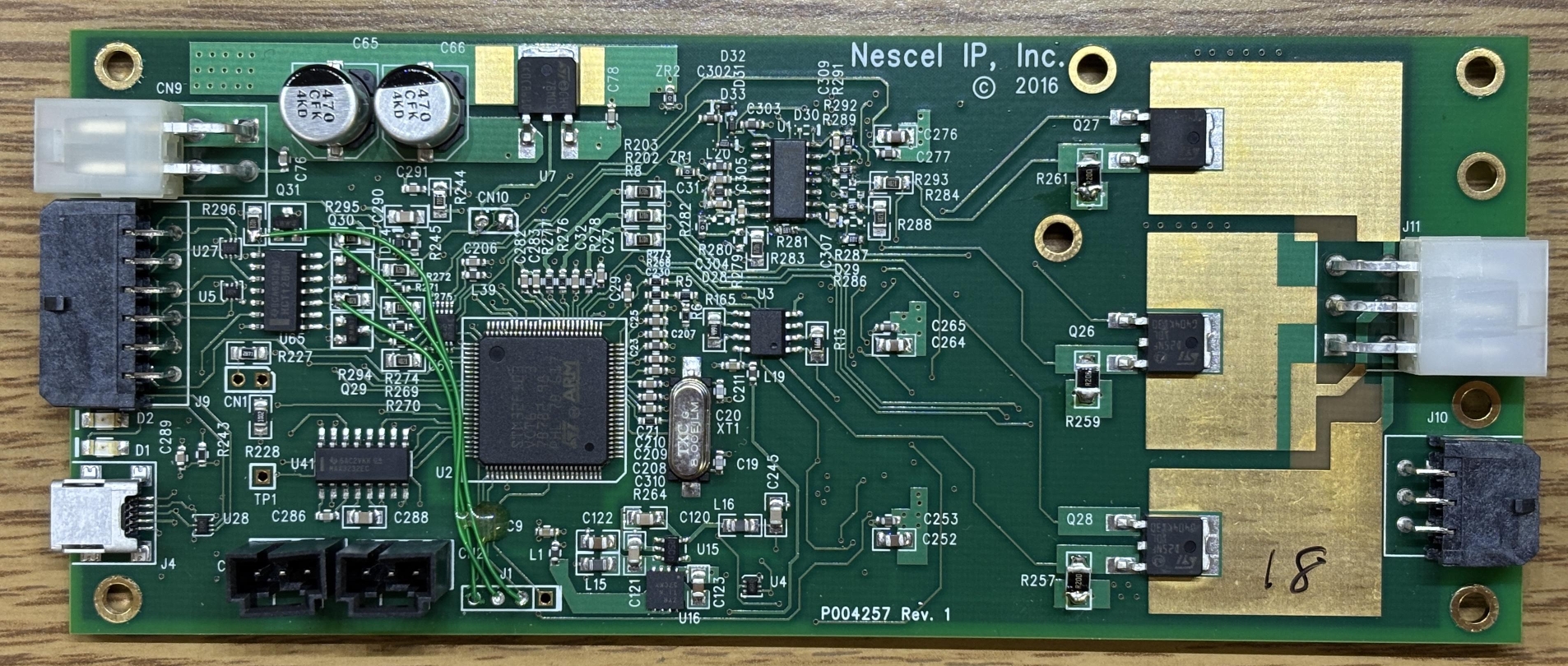
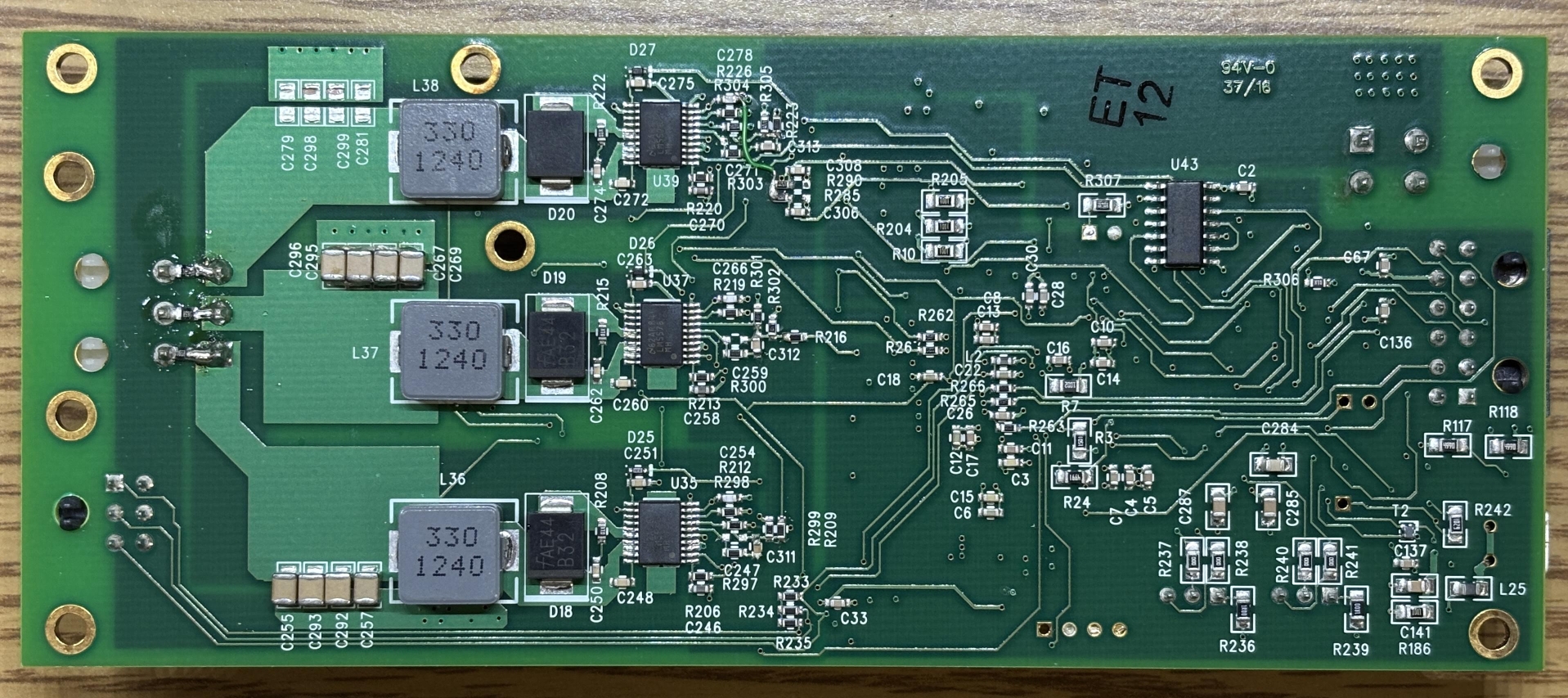
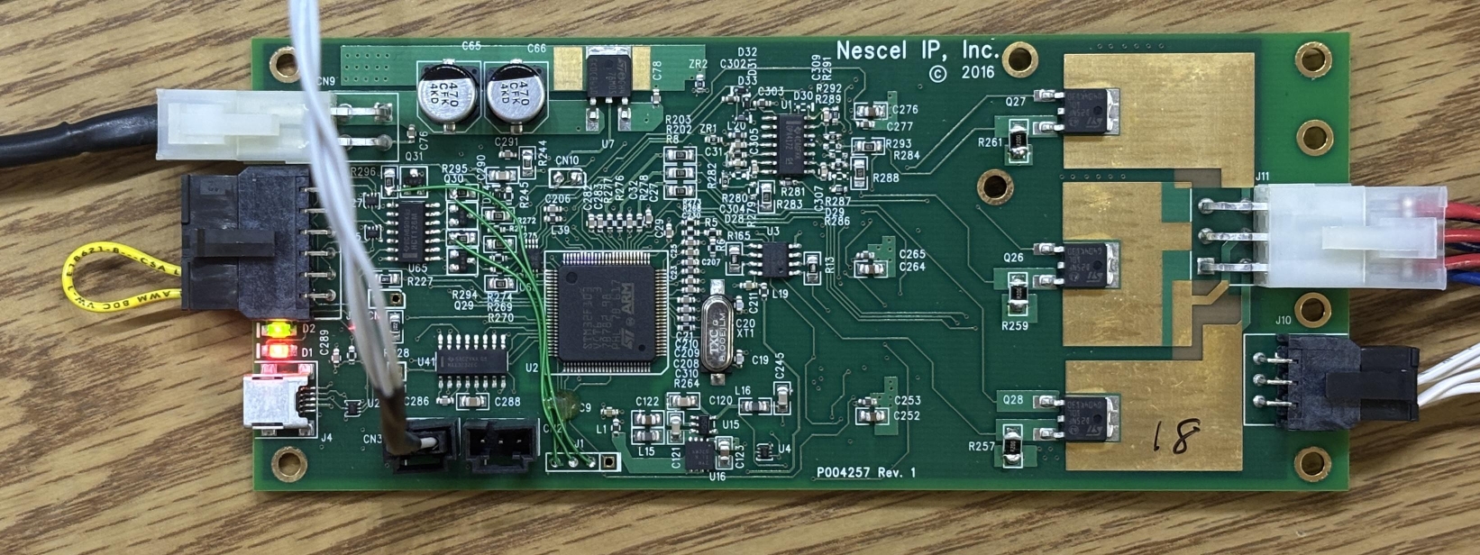
This is the diode driver and digital control board for the NovaLum 1200 laser system. The most interesting detail that we noticed right off the bat is the misspelling of the brand name Necsel in silkscreen on the board. On the board below, it is spelled "Nescel", which differs from the company name on their website (Necsel). The board is dated 2016 and offers full digital control over the laser module. According to USHIO's website, they intended for this laser to be controlled with their software over the USB interface. Unfortunately, we did not receive the software package with this laser and were unable to find it anywhere online. When we reached out to USHIO to request their "NovaLum Developer's Kit", but were met with silence. Since we couldn't even find a technical manual for a similar system, we knew we were in for a treat getting this unit working.
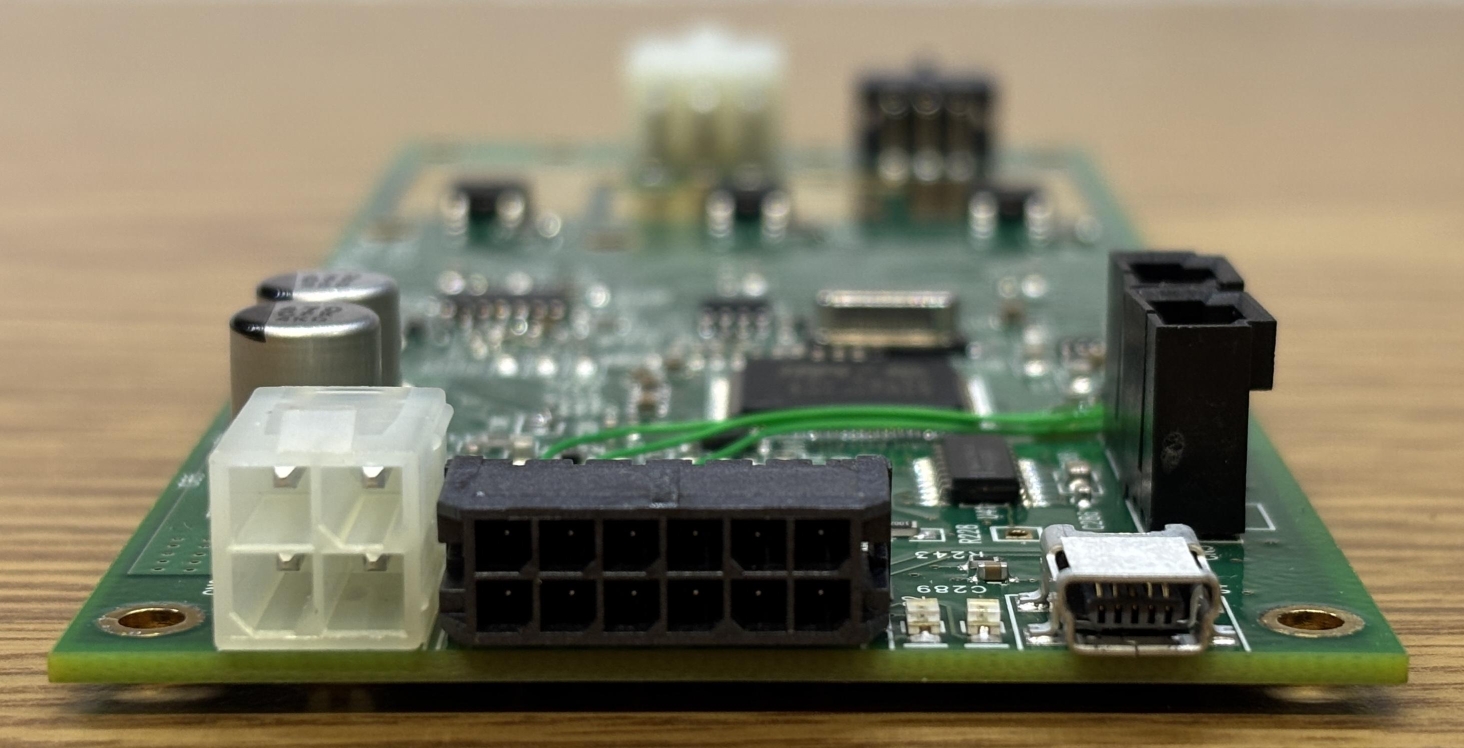
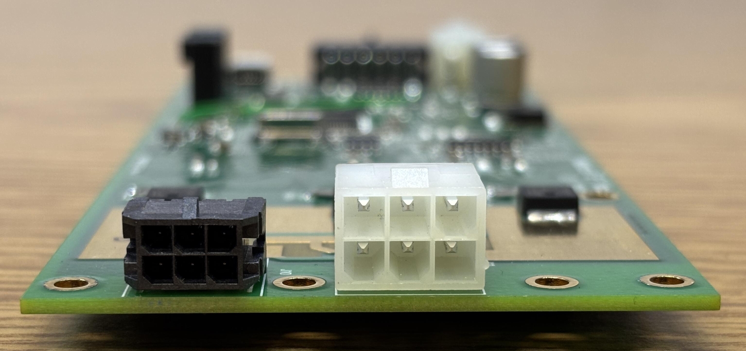
The left image depicts the input section of the board. There is a 4-pin standard Molex connector for the DC power input (15V DC, 4A), 12-pin Molex micro-fit connector for GPIO and interlocks, and a mini-USB connector for computer control. The image on the right depicts the laser head connections which are broken out into a 6-pin Molex micro-fit connector (thermistors) and a regular 6-pin Molex connector (diode power connections).
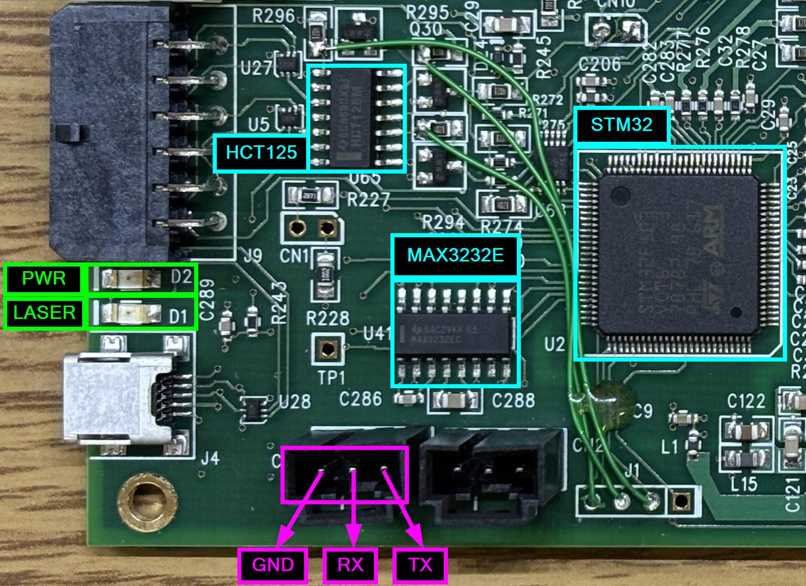
When connecting the board to the computer and powering it up, we were disappointed to learn that it's not just a USB serial port (like the Coherent Sapphire driver board). It's an actual USB device that of course requires a proprietary driver. While it is possible that some sort of generic ARM/STM32 driver could be used, we decided to examine the board a bit further. Other than the STM32 processor, there are some op-amps and several mundane components, except for a MAX3232E, which is a multi-channel RS-232 line driver/receiver. This chip is located to the left of the processor and right above two 3-pin sockets labeled CN3 (left) and CN2 (right). These sockets are interesting as they don't seem to have any documented purpose, are only internally accessible, and are located near the MAX3232E. RS-232 requires 3 signals: GND, TX, and RX. We used a multimeter to test the continuity of the pins within the sockets and trace them back to pins on the MAX3232E. Each pin of CN3 is directly connected to pins of the MAX3232E. We have now found an undocumented RS-232 serial interface! This is excellent since no special drivers or software are required to communicate over RS-232. The pinout for CN3 is provided below.
- PIN 1 (left) - GND (logic and power ground) - RS-232 GND
- PIN 2 (center) - MAX3232E PIN 13 (RIN1) - RS-232 RX
- PIN 3 (right) - MAX3232E PIN 14 (DOUT1) - RS-232 TX
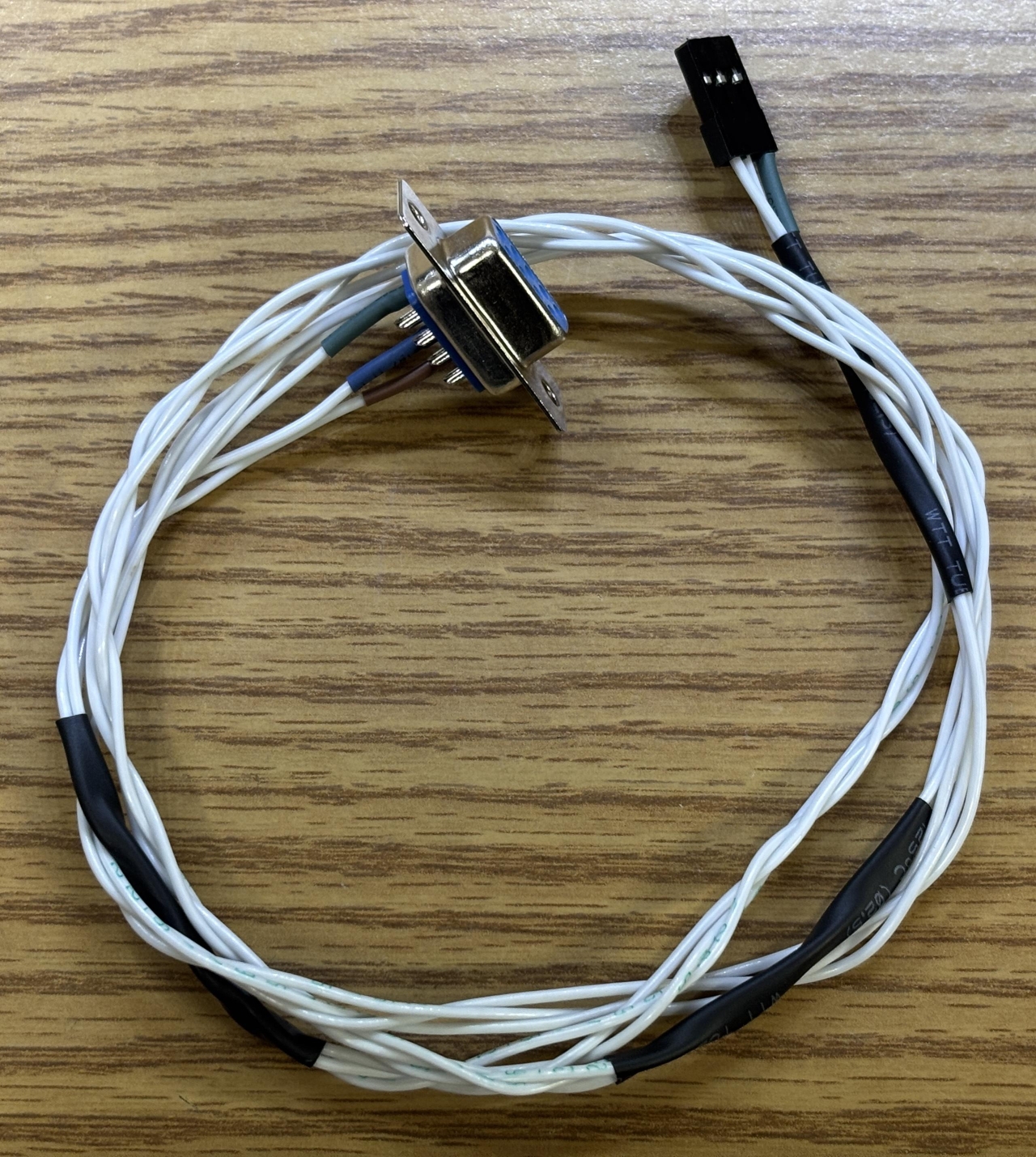
Now that we had figured out the pinout to a promising serial interface, we made a custom RS-232 interface cable that includes a DB-9 connector for a computer serial port and a 3-pin single-row header connector that inserts into CN3 on the driver board. We did try monitoring the TX line with a scope briefly, but as expected it was not sending out any data. Most laser controllers we have worked with don't send anything out by default, they have to be queried first.
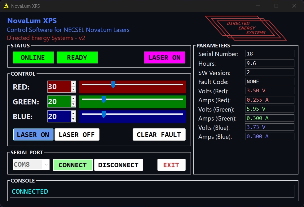
At this point, we got to play the extremely fun game of "guess the baud rate"! Using a serial terminal, we tried sending commands using several common baud rates until we eventually got a response at 115200. The first response we got was a syntax error, which make sense since we were just sending random letters while guessing the baud rate. A readable ASCII response means we determined the correct baud rate. Other lasers and many embedded devices use 115200, so at least it didn't take us too long to get to that. Now that we had successfully established serial connection, the next challenge was to figure out the command syntax. We had to do this manually since there was no command reference or documentation. Of course, there was no HELP command to display a table and just sending a ? did nothing. After a bit we did figure out some basic commands like sn? which returned the serial number, f? which returns fault state, and l0/l1 to enable/disable laser. We knew the laser enable/disable commands worked since we could watch the state of the emission LED, but we still got no output. We assumed that each color channel was just set to the minimum and needed to be increased in order to get any laser output. The green LED on the control board indicates that DC power is present, the red LED is an emission indicator that turns on when laser output is enabled.
After about an hour of throwing various commands and syntaxes at the controller, our friend proposed the idea of using Claude Code to generate a Python script to systematically guess commands and monitor the output. This ended up working extremely well and only took about 15 minutes to build a list of accepted commands and their purpose. After that, we tried each one to verify the actual function. Claude was right about most of them, but the purpose of some is still unclear. Regardless, that saved us hours of work and we'd like to give a huge thanks to our friend for helping us with this, you know who you are! We have included a table of commands below, some may have remarks or question marks indicating that we are not completely sure of the purpose. However, everything you need to get this laser working in CW mode at any color/intensity is listed below. The syntax is a bit strange, and is case sensitive. Some commands require a space between the command and value, others do not. Pay close attention to the table, we'll also provide some example commands below.
| COMMAND | FUNCTION | REMARK |
|---|---|---|
| sn? | Get serial number | |
| ver? | Get software version | |
| hrs? | Get operating hours | |
| f? | Get fault code | 0 = no faults detected, 3 = interlock fault, 7 or 10 = potentially thermal overload or driver issue |
| l? | Get laser emission status | 1 = emission enabled, 0 = emission disabled |
| pl? | Get power limit parameter | We are unsure of the exact purpose of this parameter, but it behaves like a power limit and does impact runtime. Set to 1 to prevent fault 7 after a few seconds of emission |
| ai? | Get analog input value | ? |
| Ai? / Bi? / Ci? | Get laser channel current in amps | A, B, C refer to individual diode channels |
| Ap? / Bp? / Cp? | Get laser channel power (returns current in amps) | This command has the same effect as Xi? (get laser channel current) |
| Av? / Bv? / Cv? | Get laser channel voltage | A, B, C, refer to individual diode channels |
| Ado? / Bdo? / Cdo? | Get laser channel digital output value | ? |
| cf | Clear active fault condition | Can also be achieved by power-cycling the driver |
| l0 | Disable laser emission | |
| l1 | Enable laser emission | |
| pl <n> | Set power limit parameter | Where n is either 0 or 1. We are unsure of the exact purpose of this parameter, but it behaves like a power limit and does impact runtime. Set to 1 to prevent fault 7 after a few seconds of emission. Take note of the space |
| Xi <n> | Set laser channel current | Where X is the channel ID (A,B,C) and n is a decimal or integer <= maximum channel current (enforced by firmware) |
| Xp <n> | Set laser channel power | Where X is the channel ID (A,B,C) and n is a decimal or integer, this command has the same effect as Xi (set laser channel current) |
Example commands:
- pl 1
- l?
- l1
- Ap 0.5
- Bp 1
- Ci?
We ran into some strange behavior with this system regarding thermal issues and subsequent fault codes. We are not sure if these are just problems with our unit or if they apply to other NovaLum units. If the "PL" parameter is set to 0, emission will stop after several seconds if any channel's power is set above a certain threshold (~>0.2). The driver will then go into fault mode 7, requiring a power-cycle or the clear faults command to be issued. This appears to be some sort of power limit. Setting PL to 1 removes this limit and allows laser emission at higher power levels. We also noticed the three STD25NF MOSFETS getting extremely hot during operation at greater than 25% on any channel, especially the blue. We installed a heatsink to help cool the MOSFETS, which did seem to increase runtime, but the driver would still occasionally shut down and throw fault code 10. Consider these thermal issues if you are working with a similar NovaLum unit. Perhaps there is a heatsink for the driver that was not included with this unit. Additionally, active thermal management is required for the laser head itself. A heatsink and fan may suffice, but a TEC is recommended.
We even went the extra mile and wrote a custom GUI application to control this laser. A download link for the program is provided at the bottom of this page. Just know that it comes with no warranty or support and you're responsible for the safe operation of your laser.
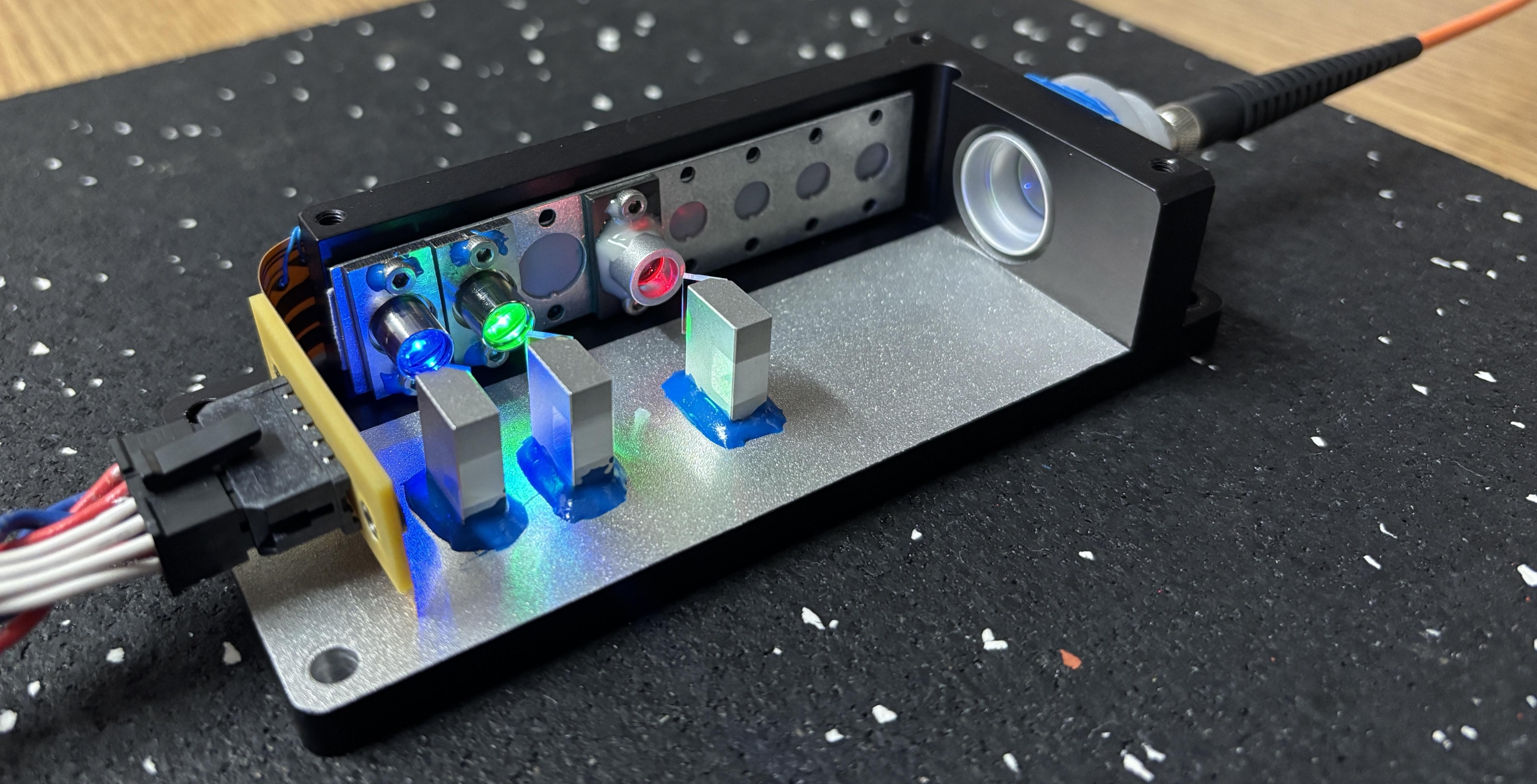
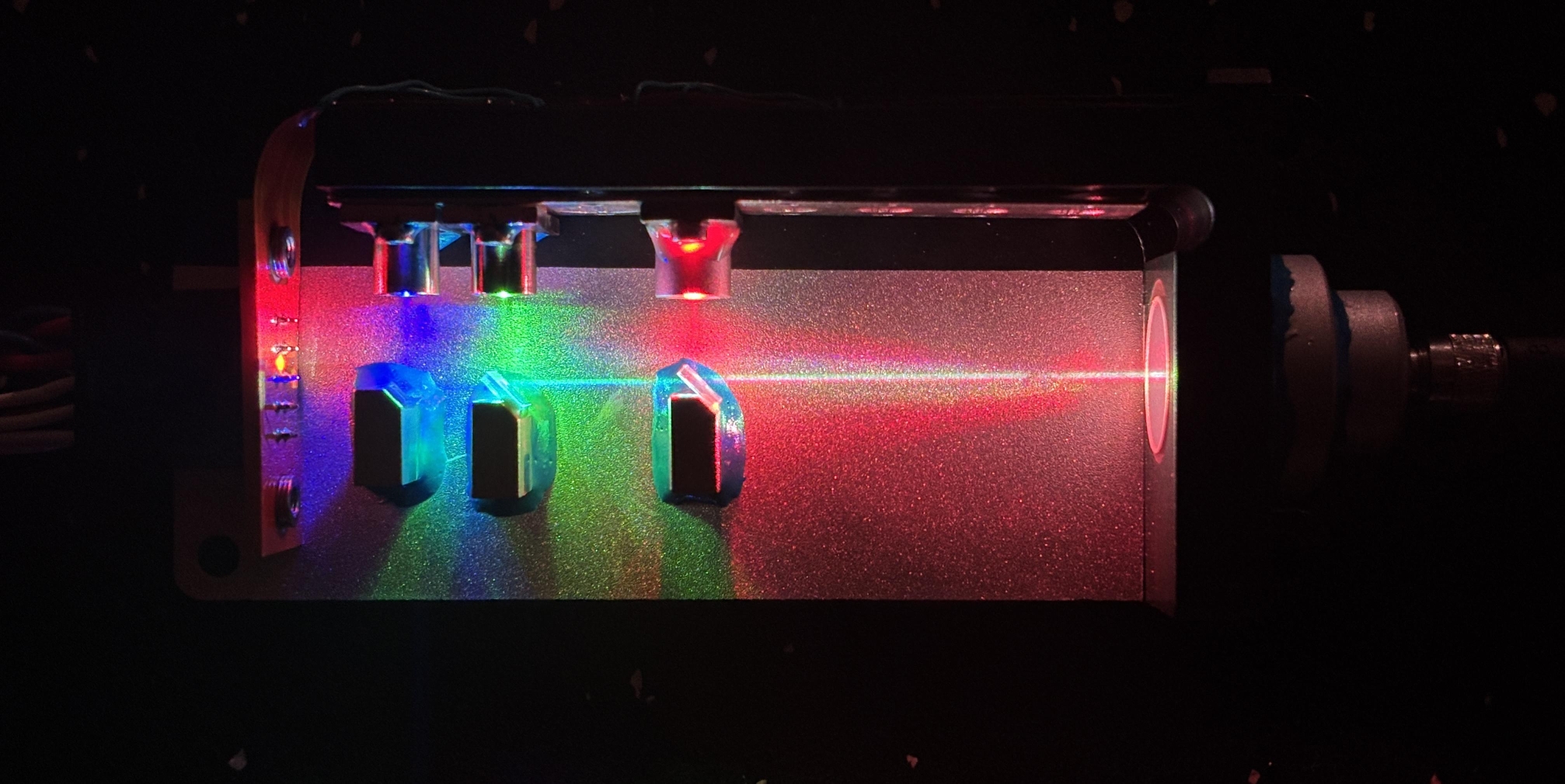
In the image below, we powered the laser on at medium intensity with the cover removed. This shows the diode colors and arrangement nicely. VCSEL lasers are interesting as they emit light perpendicularly from the top surface, compared to conventional laser diodes which emit from the edge. One advantage of VCSEL laser technology is the ability for them to be tested during various stages of manufacturing, compared to traditional laser diodes which can only be tested at the end of production. VCSELs can also be manufactured in two-dimensional arrays, allowing for finer wavelength tuning and improved power densities for high-power units.
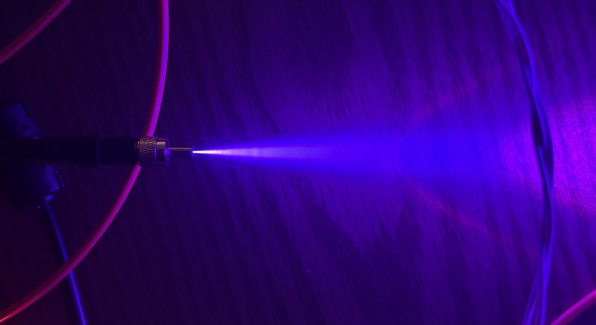
We used a fog machine to make the beam path a bit more visible in the image below. As a side note, it would be neat to see if this unit could be integrated into a laser show projector. Analog or TTL control over the diodes would be needed and the beam would need to be collimated much better, but it's possible!
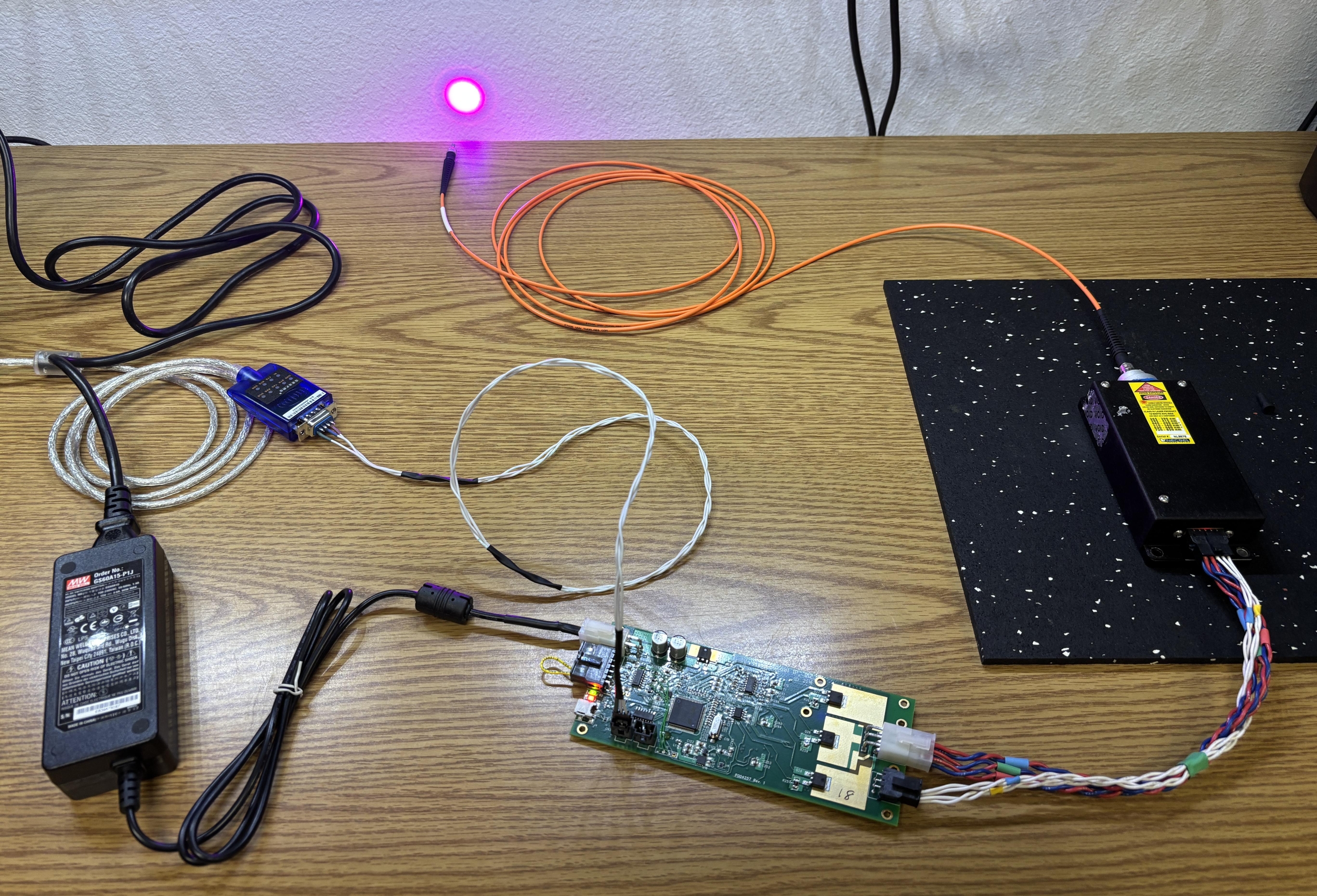
Here is the complete setup including the laser head, driver board, USB-to-serial converter, custom interface cable, power supply, and fiber cable. The beam makes a nice large dot as it exits the fiber. A collimating lens can be attached to the end of the fiber to produce a smaller and denser beam.
The image below shows just how much the beam diverges after exiting from the fiber.
Visit the links below to learn more about this laser as well as VCSEL laser technology!