The Jenoptik JenLas D2.3 is a DPSS laser that uses Thin-Disk technology to deliver up to 5 watts of 532nm laser light. Like most laser systems we work with, there are many technical and scientific applications for a system like this. According to the brochure, Jenoptik lists a variety of applications for this laser system including display engineering, light shows, medical systems, manufacturing, and more. A friend allowed us to borrow and disassemble this laser for examination. It was likely stripped from a piece of scientific equipment and listed for sale online. At the time of writing, we were able to find a similar unit listed for sale on eBay that was removed from a medical device.
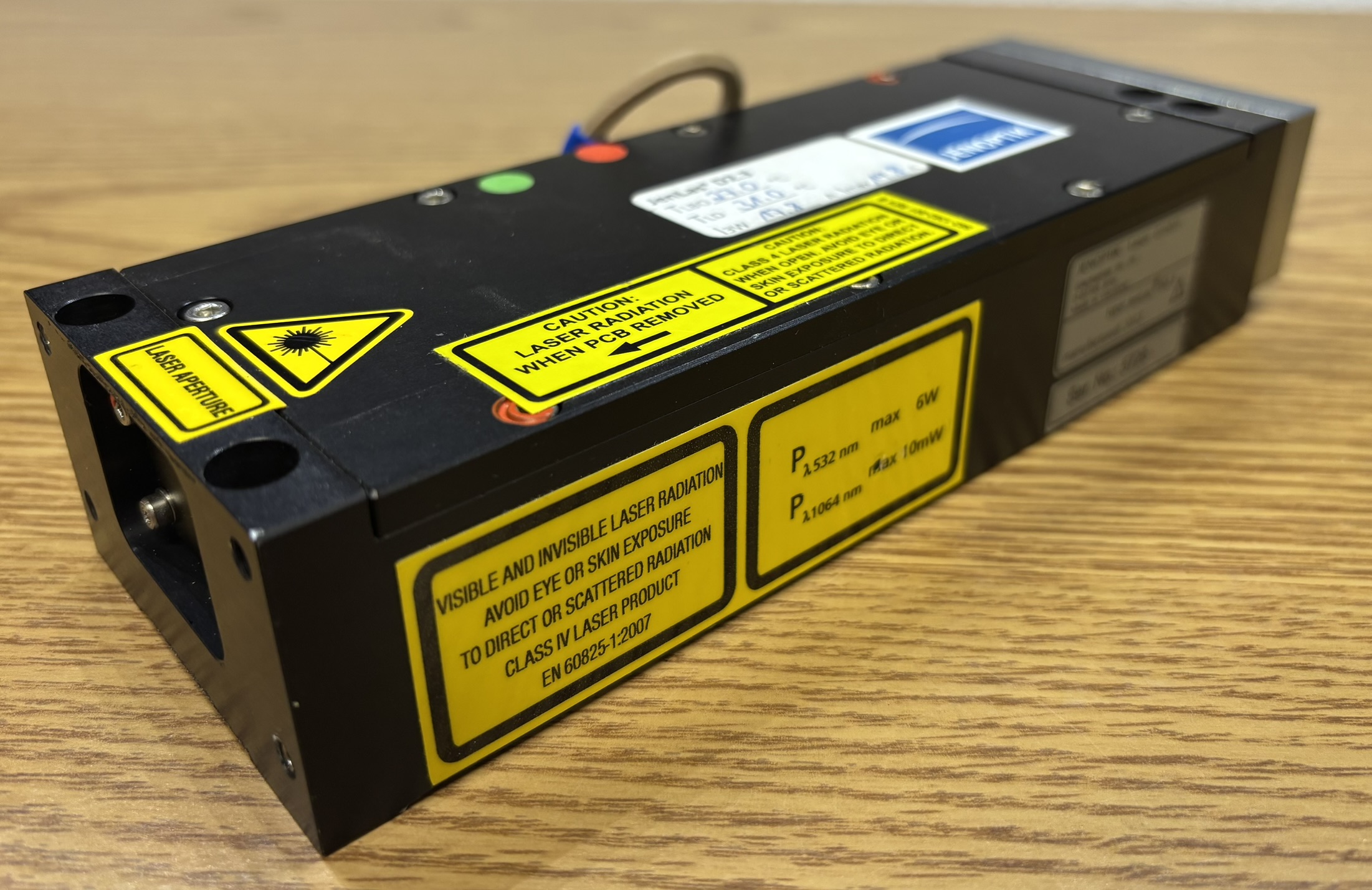
The laser head is quite heavy, being made entirely of thick, precision-milled, aluminum.
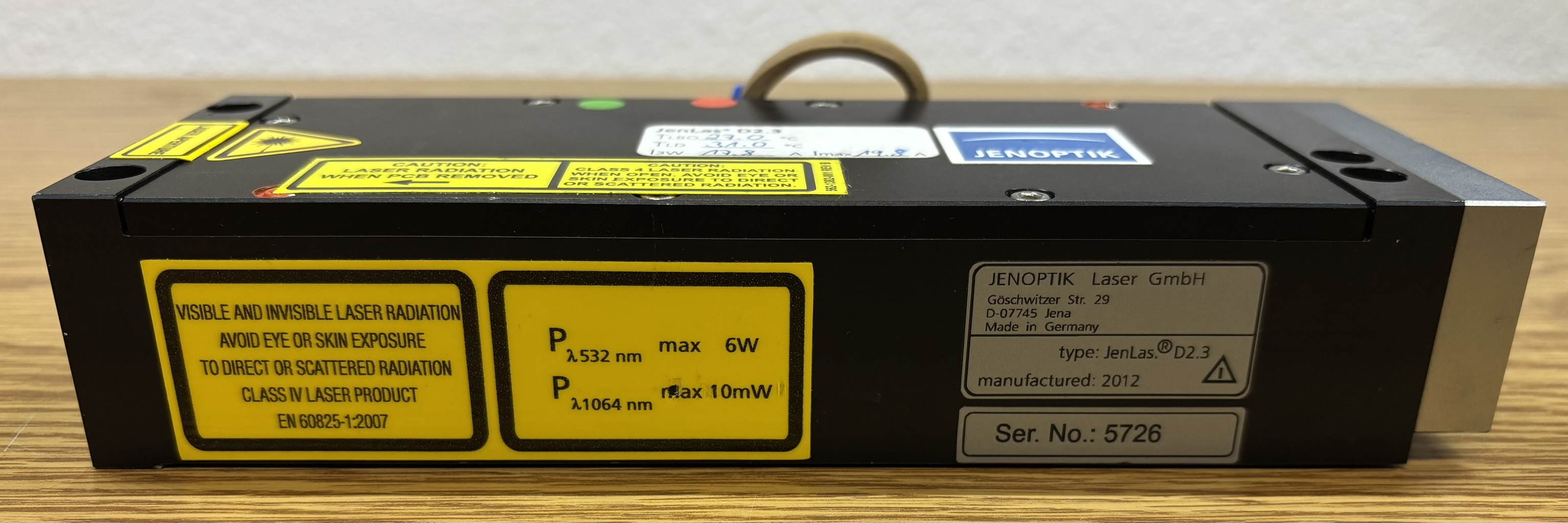
The top cover is held on with several hex screws and contains some interesting information regarding maximum component temperatures and maximum diode current.
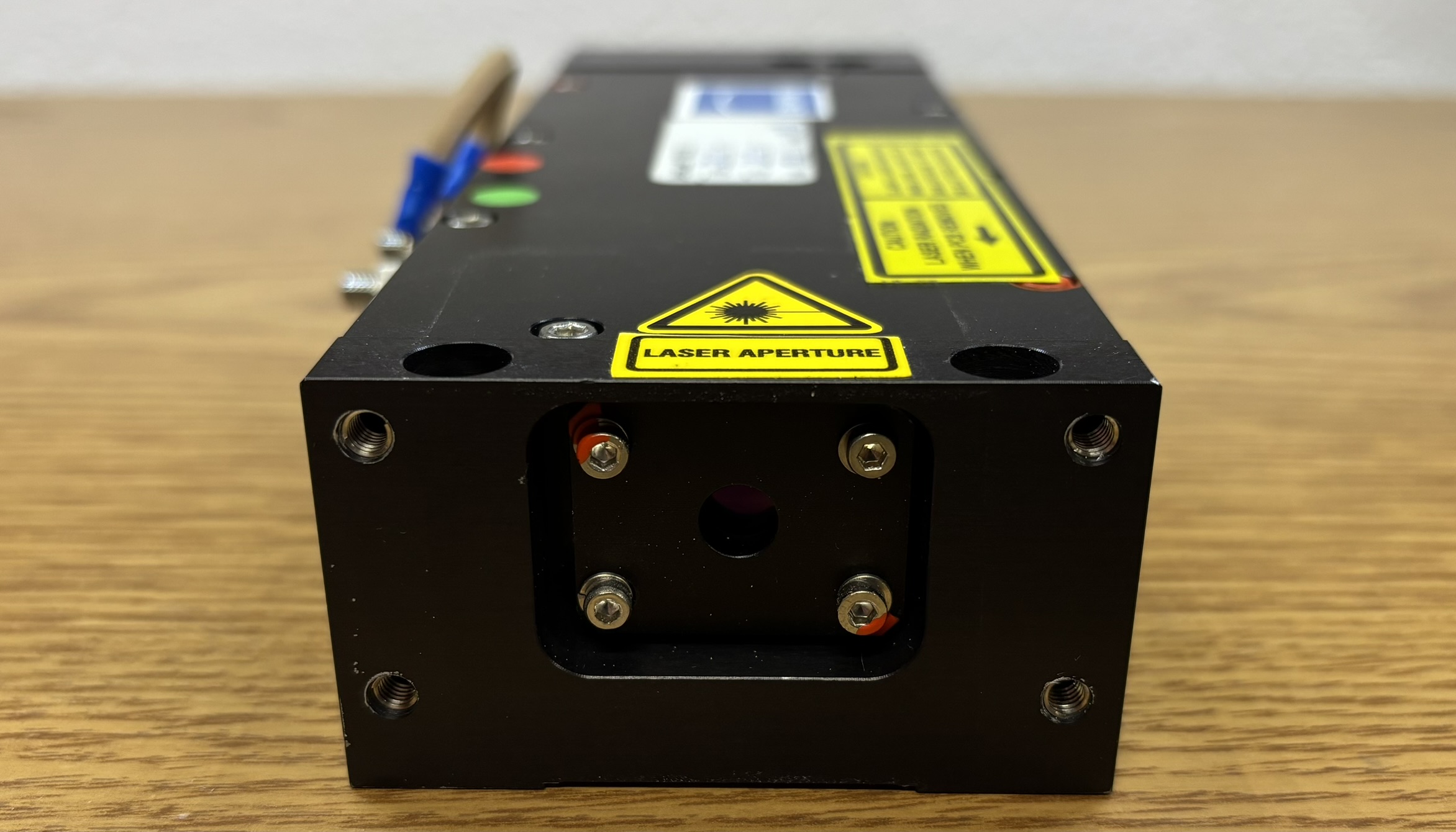
On the front of the laser head, there is a plate with an adjustable output window, the four small hex screws allow this to be removed and adjusted. Interestingly, there is no beam shutter on this laser, indicating it was likely a component installed into an OEM system and never operated standalone.
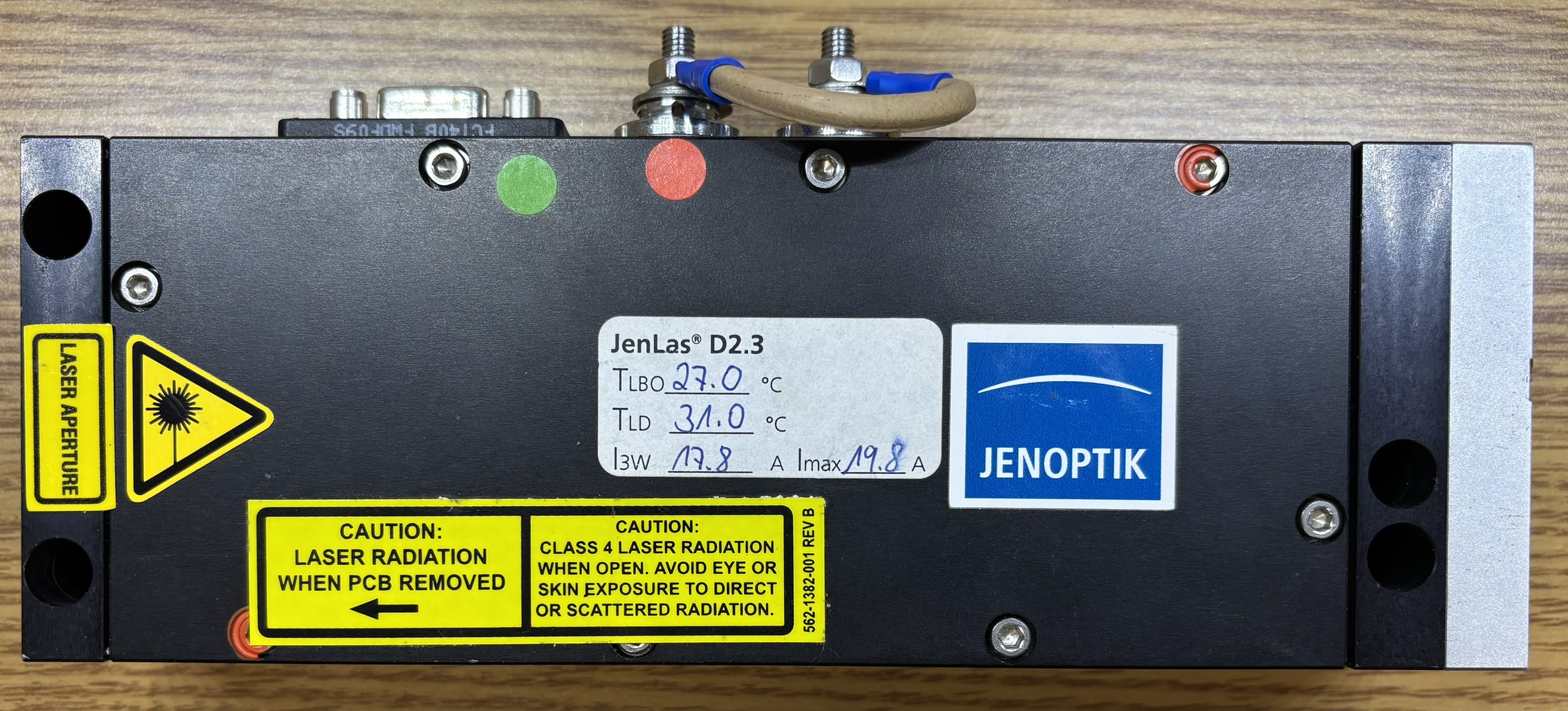
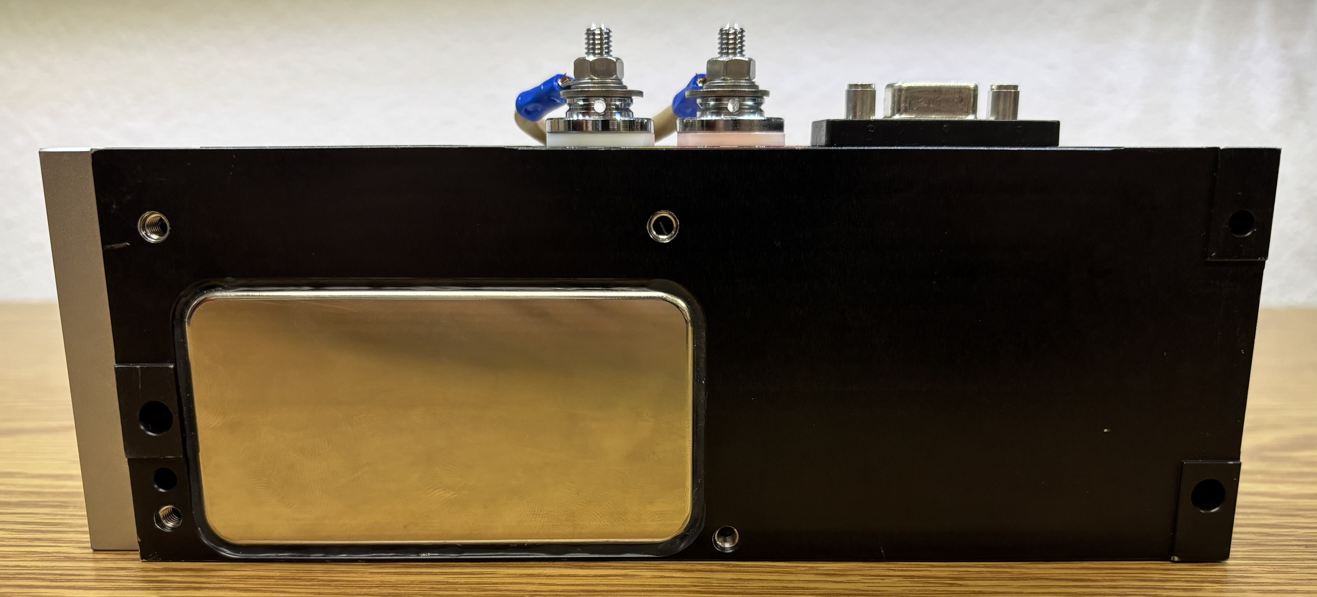
On the side of the laser head, there are two large binding posts for the laser diode connection. The diode connections should be shorted together when not in use to prevent damage from static discharge. A female DB-9 port provides the connections for the internal TEC and thermistors. A pin-out for the DB-9 connector is provided below the image. The 20W pump laser diode can be driven to a maximum current of 25A at 2V DC. Limiting the current to 20A is recommended to preserve the life of the diode. The internal TEC for the LBO can be connected to a TEC driver providing ~1.5A at 4V DC. Additionally, if the laser head is equipped with an external TEC and heatsink, this will need sufficient power to cool the system.

| PIN | FUNCTION |
|---|---|
| 1 | LBO THERMISTOR |
| 2 | LBO THERMISTOR |
| 3 | N/C |
| 4 | N/C |
| 5 | TEC POSITIVE (+) |
| 6 | PUMP DIODE/HEAD THERMISTOR |
| 7 | PUMP DIODE/HEAD THERMISTOR |
| 8 | N/C |
| 9 | TEC NEGATIVE (-) |
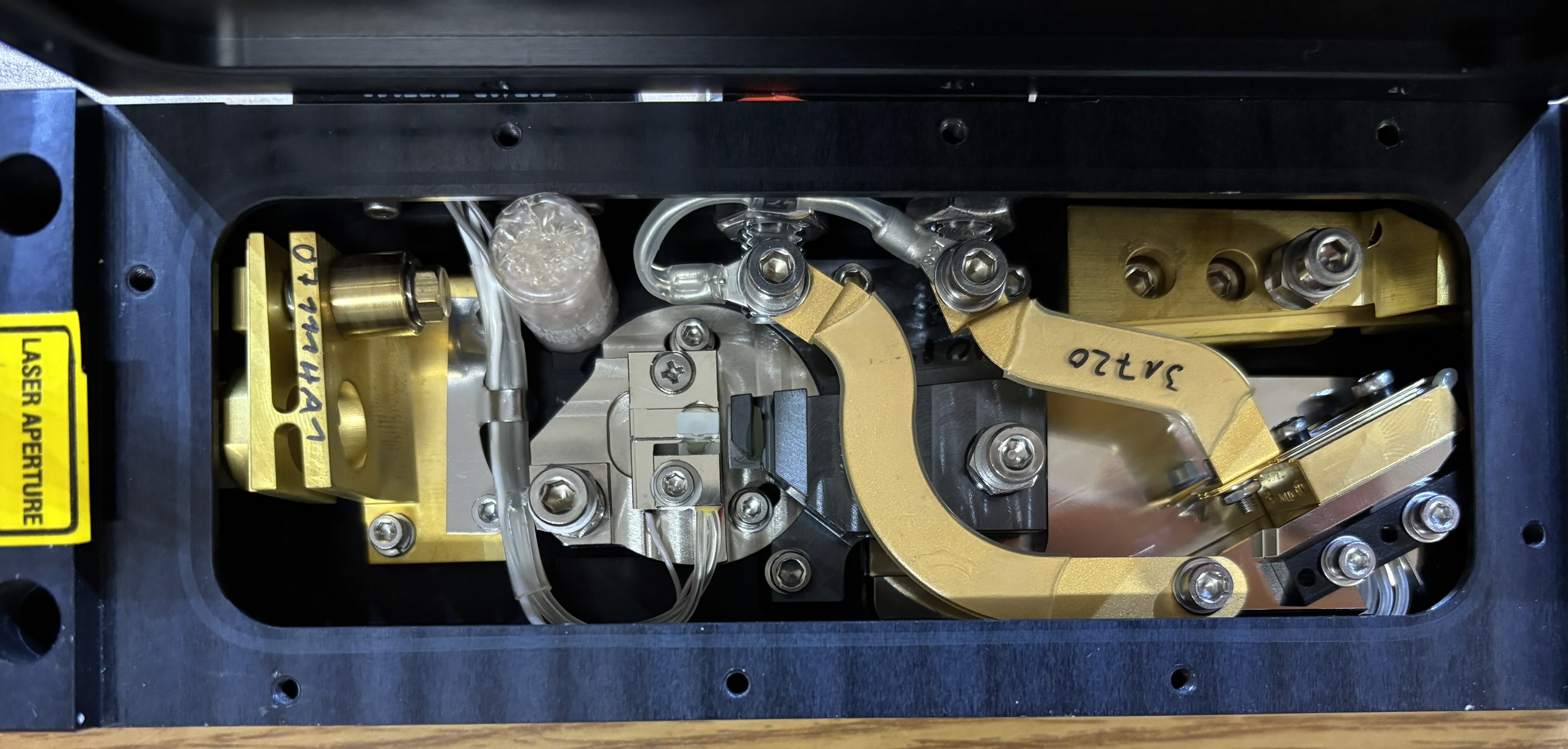
Behind this aluminum cover is the Thin-Disk. It is installed in a mount, which is secured to the aluminum plate, which is secured to the rest of the laser head with four screws. We did not remove this aluminum plate as doing so could risk putting the laser out of alignment. Thin-Disk laser technology works similar to OPSL technology, which uses a specially constructed semiconductor to convert one wavelength of laser light to another. Unlike common laser optics, such as nonlinear crystals, the Thin-Disk is not a transparent crystal, it's better described as an opaque block. The Thin-Disk is not a passthrough optical device like a crystal, it's reflective like an OPS chip. The actual Thin-Disk material is Ytterbium-doped yttrium aluminum garnet (Yb:YAG). Additionally, there are two positive-meniscus lenses mounted directly in front of the thin disc, which focus the output into a small dot of laser light. 808nm light enters from left side lens, hits the Thin-Disc, and is directed into the right side lens after being converted to 1064nm light.
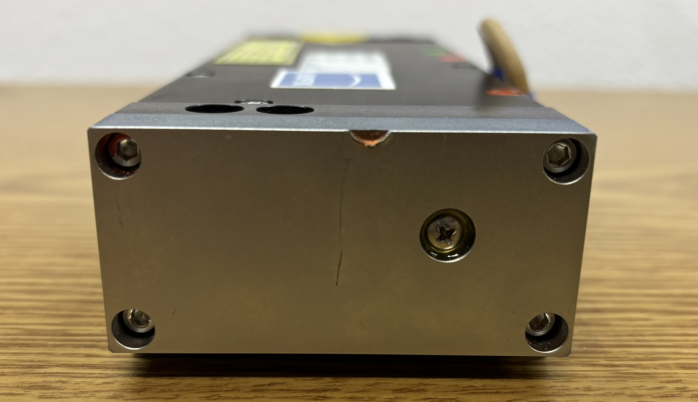
Active cooling of the laser system, via TEC, is critical. This is due to the inefficient nature of the pump diode. There is a smaller section of smooth aluminum on the bottom of the laser head that serves as the thermal interface surface for the pump diode.
The beam path for this laser system is as follows: Up to 20 W of 808nm laser light emitted from the pump diode first passes through a FAC lens mounted directly in front of the emitters of the pump diode. Take note of the two high-current bus-bars that connect the pump diode to the positive and negative terminals on the outside of the casing. Next, 808nm laser light from the pump diode is condensed down through the first positive meniscus lens, and then hits the Thin-Disc. The 808nm light excites the Yb:YAG material, resulting in the production of 1064nm laser light, which reflects off the Thin-Disk and through another positive meniscus lens for beam shaping. It then continues towards the front of the laser head. The laser light hits the front output coupler, which is installed in an adjustable torsion mount. Light reflects off the output coupler and is directed towards an LBO crystal. This crystal must be held at a specific temperature for optimal performance, this is achieved by the TEC mounted below the LBO crystal platform. A NTC thermistor provides temperature monitoring and feedback. Mounted behind the LBO crystal is the high reflector. As the 1064nm light passes through the LBO crystal, the process of SHG takes plate. This doubles the frequency and halves the wavelength, resulting in the production of 532nm laser light. After bouncing off the high reflector, it exits through the output coupler as 532nm laser light. The output coupler is specifically coated to reflect infrared light such as 1064nm and pass 532nm light. The small cylinder near the output coupler contains a desiccant packet. Use extreme caution when operating a laser system like this with the cover removed, dangerous amounts of invisible infrared laser light may be present!
