The YLP-R-0.3-A1-60-18 is an Ytterbium pulsed fiber laser manufactured by IPG Photonics. We will refer to it as that from now on instead of that ridiculous part number. The YLP is a 1064 nm class 4 laser with a typical output power of around 18 W (watts) and a peak pulse power of over 1kW! That is no joke, protective eyewear is a must when working on systems like these. It's especially dangerous since the 1064 nm beam is invisible to the eye but absolutely still capable of causing burns and irreversible eye damage. This particular system is likely a custom OEM product as we were able to find no references matching the exact model number, but are confident that it's at least based off the YLP or YLR series. This is common with lasers purchased online and secondhand. They are often removed from machinery or specific applications and were never intended to be operated on their own. While it did take some work, we were able to get this laser up and running and discovered many bizarre and fascinating optical design characteristics along the way. Common uses of lasers like these include production marking, engraving, and micro-machining. The laser system is made up of two different modules that are permanently connected via a thick, flexible fiber cable (which also carries electrical signals). Combined in a 6U, 19-inch rackmount case is the controller and all optical components related to laser generation, switching, monitoring, and control. This is essentially the "laser engine". Laser light passes through the fiber cable to a smaller laser head module. The laser head contains no active circuity other than a thermistor and is strictly for combining the fiber, shaping the beam, and serving as the output device.
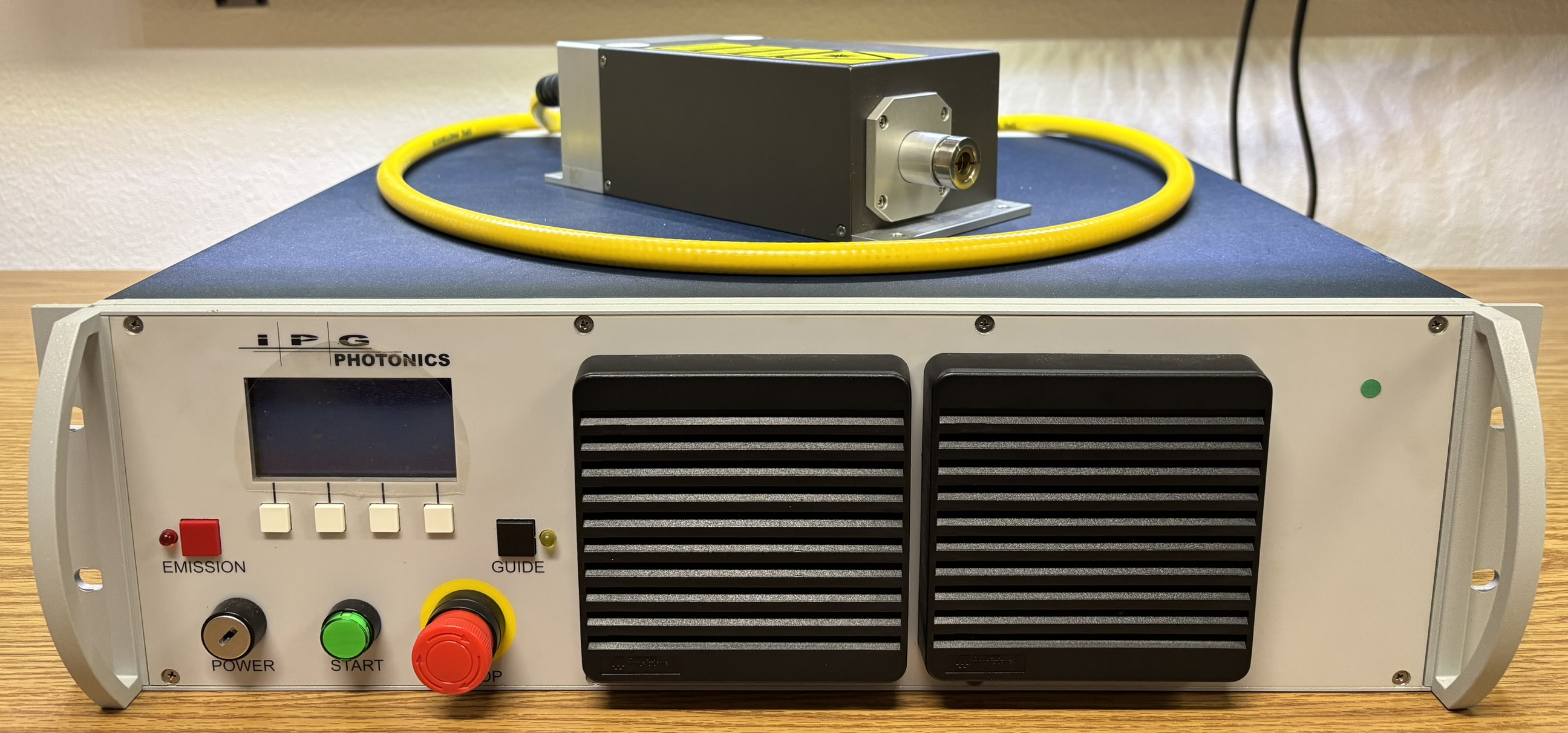
The front of the controller has two air inlets along with the user interface panel. The key-switch labelled POWER is used to enable the DC housekeeper power supply and will activate the digital control board. In this particular system, the key-switch is damaged and stuck in the on position without the key inserted. This puts the system out of CDRH compliance and would not be acceptable in a commercial setting. Once control power is turned on, the START button will enable the diode driver power supply, as long as the interlocks are closed. The red E-STOP button along with a rear interlock connector make up the interlock circuit. Since this is a class 4 laser system, it cannot be capable of lasing upon startup, therefore the green start button must be pressed each time the system is powered on. A small LCD screen along with some buttons allow the system to be controlled locally at the front panel. The GUIDE button will enable a low power guide laser if equipped, and the EMISSION button enables the main laser diodes. Below are some images of the different screens displayed based on the laser operating mode.

On the back panel, there are several fans mounted inside the case that pull air through the front, over the resonant cavity heatsink, and exhaust out the back. All the way on the left is the yellow fiber cable, which is permanently attached to the laser head and the laser engine. The cable is quite flexible and contains multiple strands of fiber along with a couple thin wires. Next is a BNC connector for modulation. This is a TTL modulation input, not analog. If left low (0V), there will be no laser output, pulling it high (5V DC) will enable laser output. While this is an external modulation connector, it's not optional and you will not get any laser output if it's left unconnected. Next is the RS-232 serial connector. We will go into more detail on the serial interface later, but it's important to note that the TX and RX pins are reversed, so take that into account or use a crossover cable when establishing a serial connection with this laser. The INTERFACE connector is a mystery as we have been unable to find a reference to it in any documentation. Luckily, no connections are needed on this connector for the laser to work. The INTERLOCK connector serves as the external interlock and can be closed by bridging the top two and bottom two pins of the 4-pin connector. This will close the external interlock circuit and enable the START button on the front panel. Pressing the START button with the interlock open will result in nothing happening. Lastly, there is a fused IEC connector for the AC line input. While this is a high power laser, it does not draw too much electrical power and should not trip a 15 A circuit breaker.


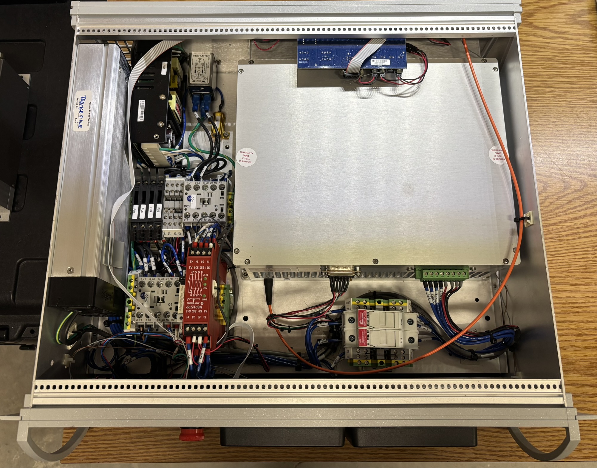
Taking a look at the inside of the controller is where things start to get interesting. On the left is the large diode driver power supply, with high current DC connections on the back. Next to it is a much smaller open-frame DC power supply for the controller, relays, etc. This is the "housekeeper" power supply that is enabled by the key-switch. Next are several components all mounted to DIN rails. The two large Allen-Bradley contactors completely isolate the input and output of the diode driver power supply when they are not energized. The bright red device is an Allen Bradley GuardMaster MSR127RP intrinsically safe relay, or safety relay. These relays are designed to be extremely reliable and only fail in a safe condition, which would be open circuit. When all interlocks are closed and the start button is pressed, the safety relay is energized, which then energizes both contactors. There is a smaller socketed relay next to the safety relay that is activated by the key-switch to enable the control system components. The control system voltage in this laser is 24 V DC. There are ample DIN rail mounted terminal blocks and fuse holders throughout. Along with excellent component and build quality, it's clear that safety was high on the priority list. Additionally, it's nice to see every wire, terminal, and component clearly labelled with numbers and identifiers. If we had the service manual, repairs would be a breeze! The large aluminum enclosure where the fiber emerges from is the resonant cavity, which contains the diodes and other optical components.
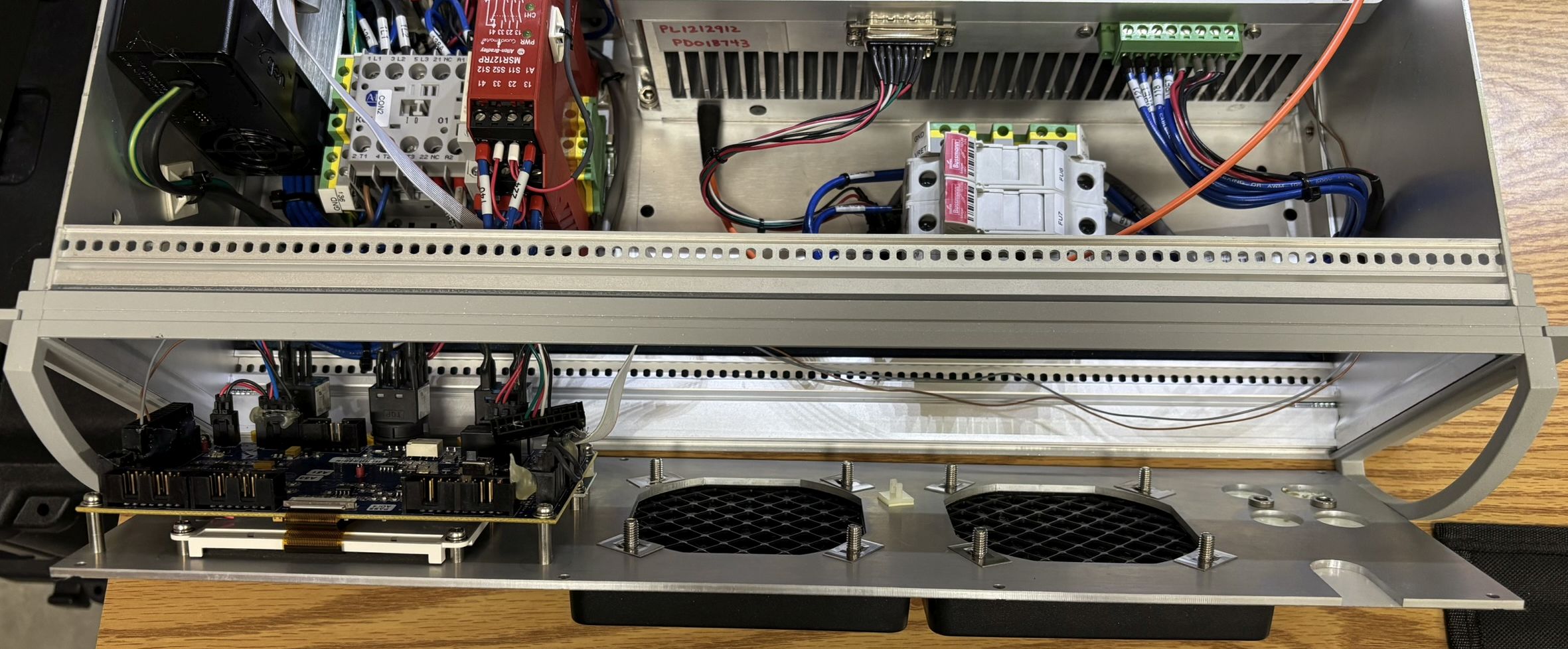
The front panel is held on by 8 screws around the perimeter. Once removed, the front panel can be hinged off but is still retained by several connectors and wiring for the switches. IPG Photonics used quality components manufactured by IDEC for the key-switch, start button, and E-stop button.
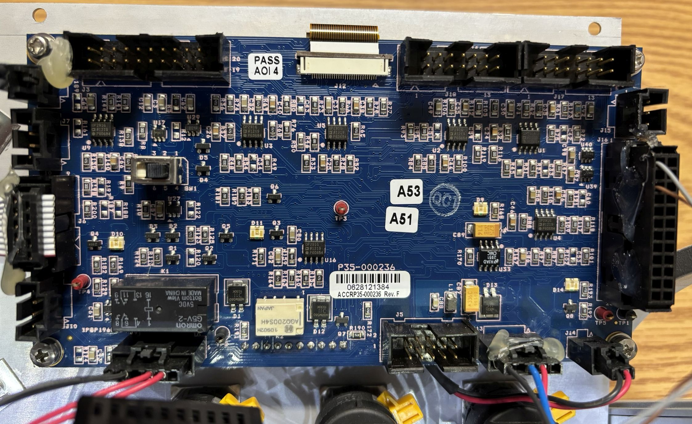
Below is the back side of the digital control board mounted to the front panel. There are several unused connectors, test points, and a switch on the back. A standard ribbon cable is used to connect the front panel button matrix and the LCD display is connected via a flat-flex ribbon cable.
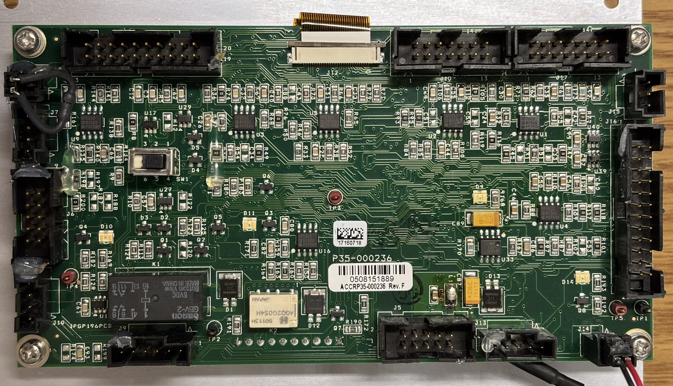
Here is a picture of the same control board from an identical system. Other than the green PCB color, the components and board design are the same. Both boards share the same part number of ACCRP35-000236.
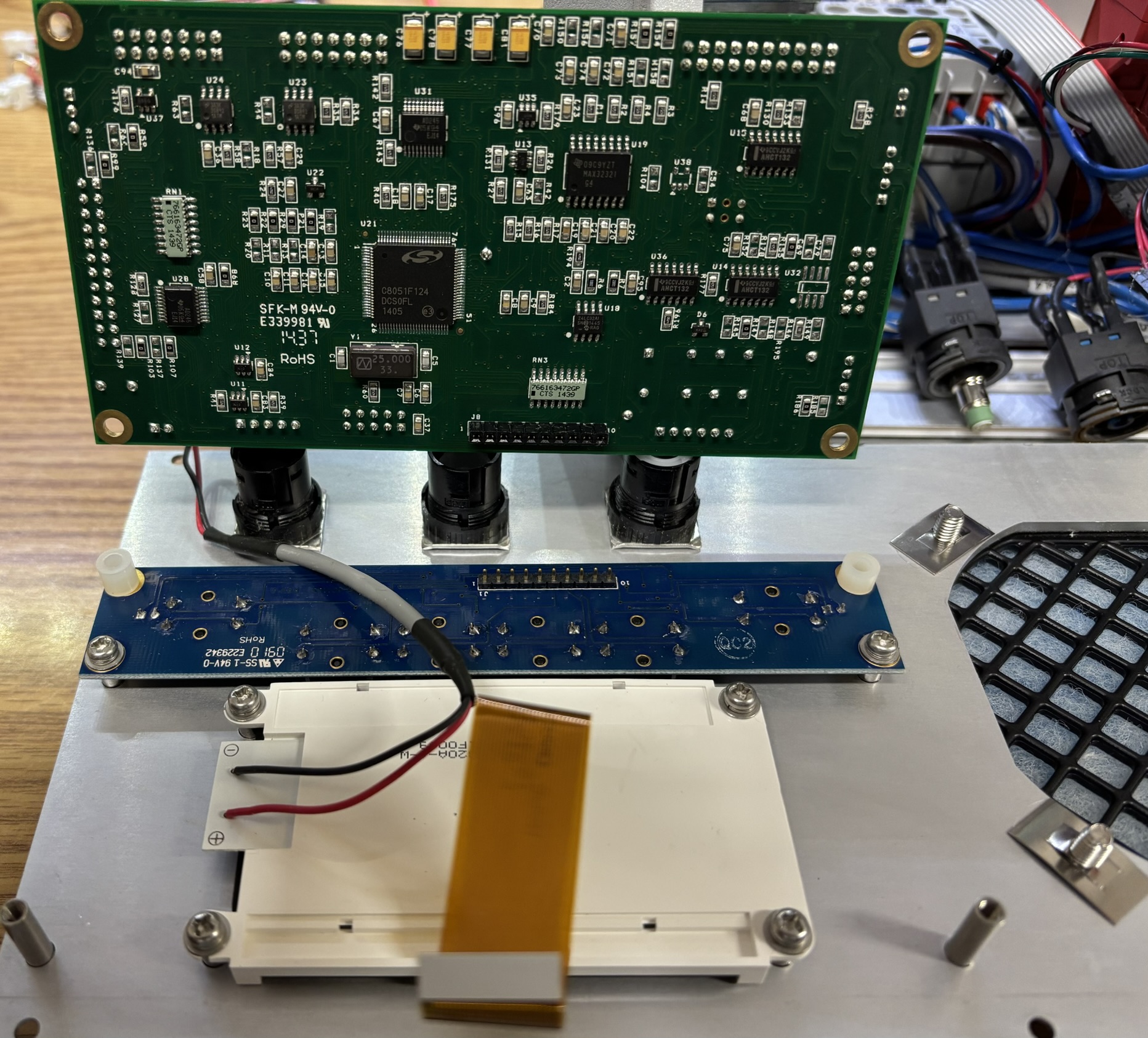
Removing the four screws allows the control board to be disconnected from the single-row pin header on the button board. The back side of the LCD display is also visible.
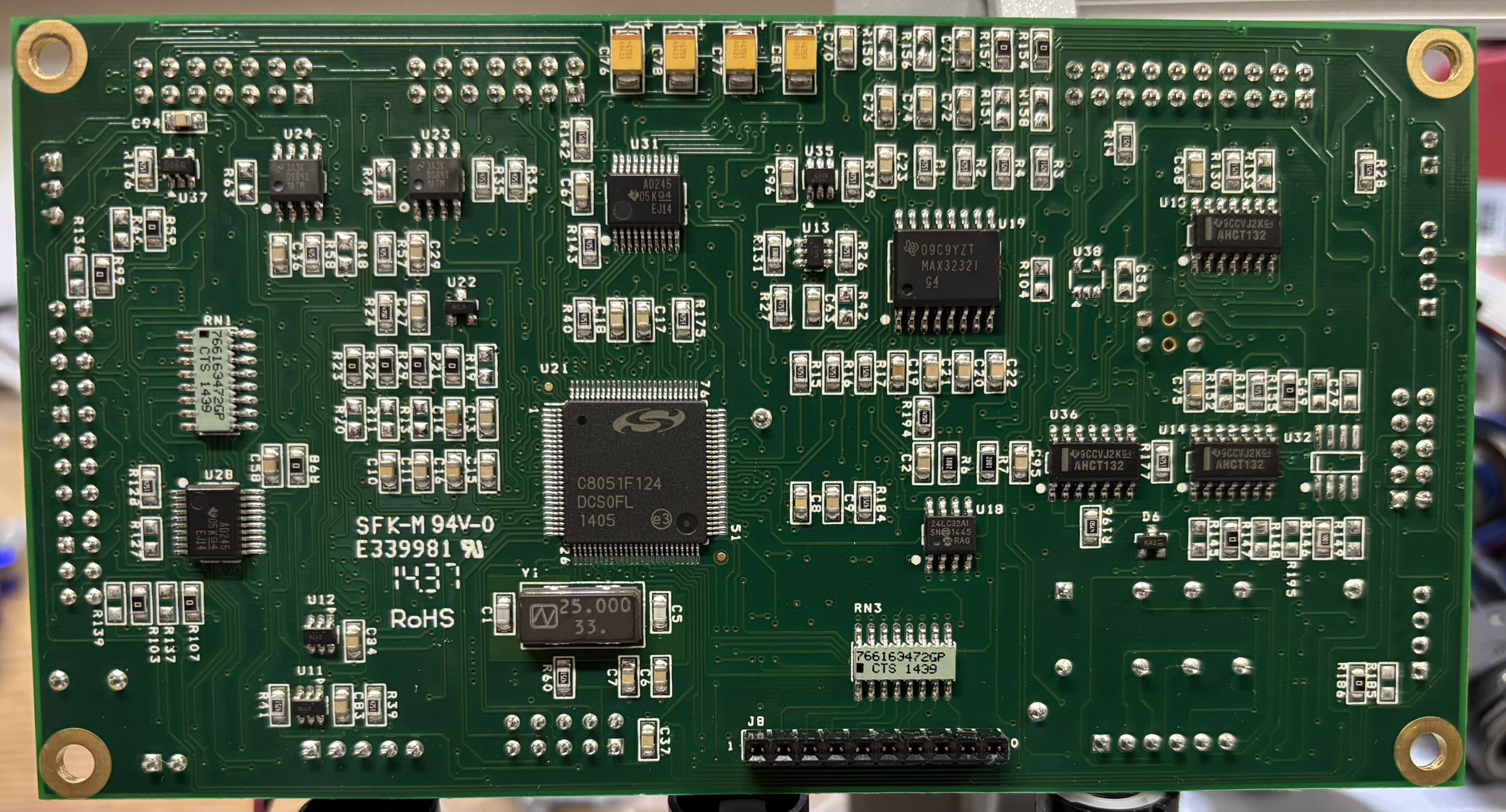
The other side of the control board reveals the MCU, which is a Silicon Labs C8051F124 8-bit "analog-intensive" microcontroller. We read the data out of the small EEPROM located near the MCU, but it was essentially blank.
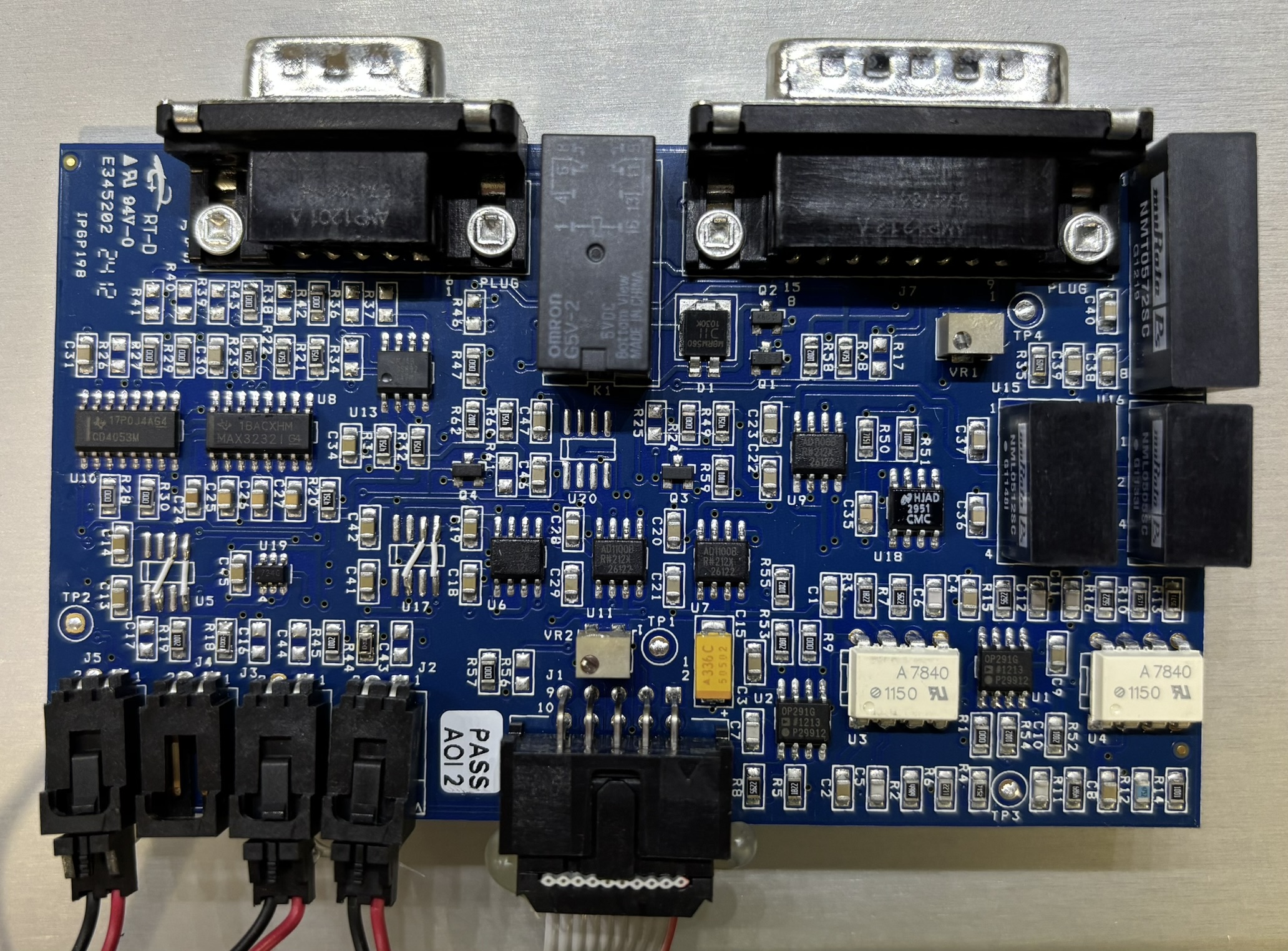
Next is the RS-232 serial and INTERFACE junction board that is secured to the back case panel by the retention screws on both the DB-9 and DA-15 connector. Noteworthy components on this board include a couple of opto-isolators, potentiometers, a relay, and some MuRata isolated DC-DC converters. We suspect that the INTERFACE connector is used for analog control of the laser system, which would explain some of these components. A ribbon cable connects this board back to the front digital control board.
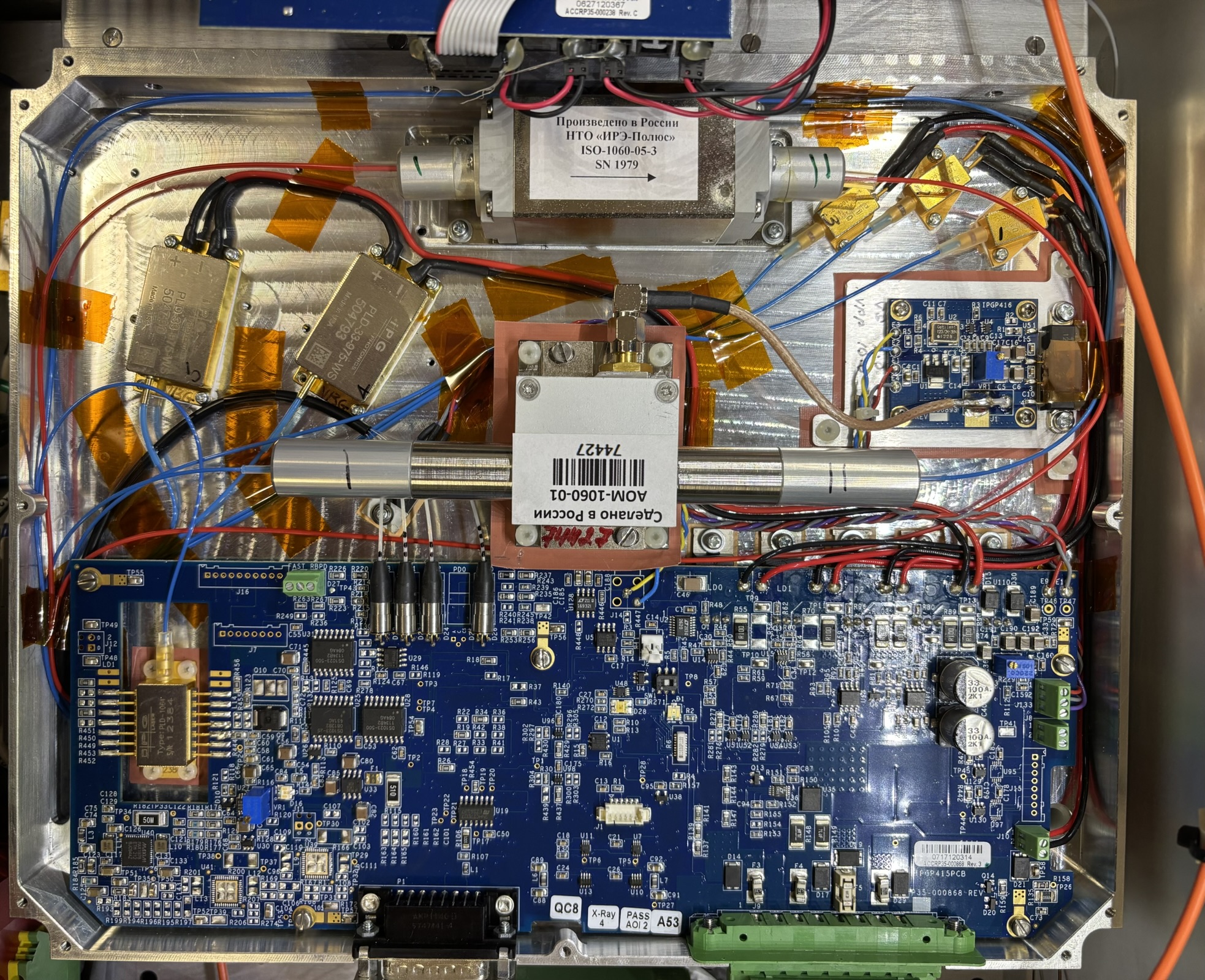
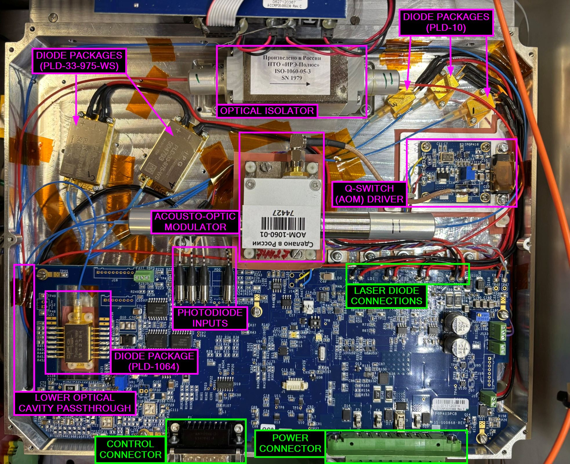
Inside the resonant cavity is where things get even more interesting! It's not a sealed cavity as all optical components are connected via fiber, there are no free-space beams. There is a large circuit board that is responsible for providing power, monitoring, and control to the diodes and other components. Laser light is generated by several individual diode packages mounted to the aluminum enclosure. There are two groups of diode packages, and one standalone package located within a cutout on the circuit board. Each diode package has an individual fiber output that disappears into the bottom section of the optics enclosure. The most interesting part of the assembly are the two optical components that are made in Russia! One is an optical isolator, and the other is an Acousto-optic modulator (AOM) used for Q-switching. The optical isolator (ISO-1060-05-3) is a passive device that prevents damage from reflected light and also ensures output power stability. This is a pretty exotic component that is not used in most systems that we work with. Take note of the arrow on the isolator that indicates the direction in which light travels. The other component of Russian origin is the Q-switch (AOM-1060-01), which connects via a small coax cable with SMA connector to an RF exciter board. The exciter board is powered and controlled by the main circuit board. Q-switching is used in laser systems to modulate output power at much higher frequencies than would be possible by pulsing a diode or operating an electromechanical shutter. Seeing components from Russia in a laser system manufactured in 2012 and sold in the USA was quite surprising. Ironically, at least some of the diode packages appear to be made in the USA.
Below is an annotated image of the optical enclosure where we attempted to identify as many components as possible. Due to the complexity of the fiber arrangement, we are not yet able to provide a beam path diagram for this system.
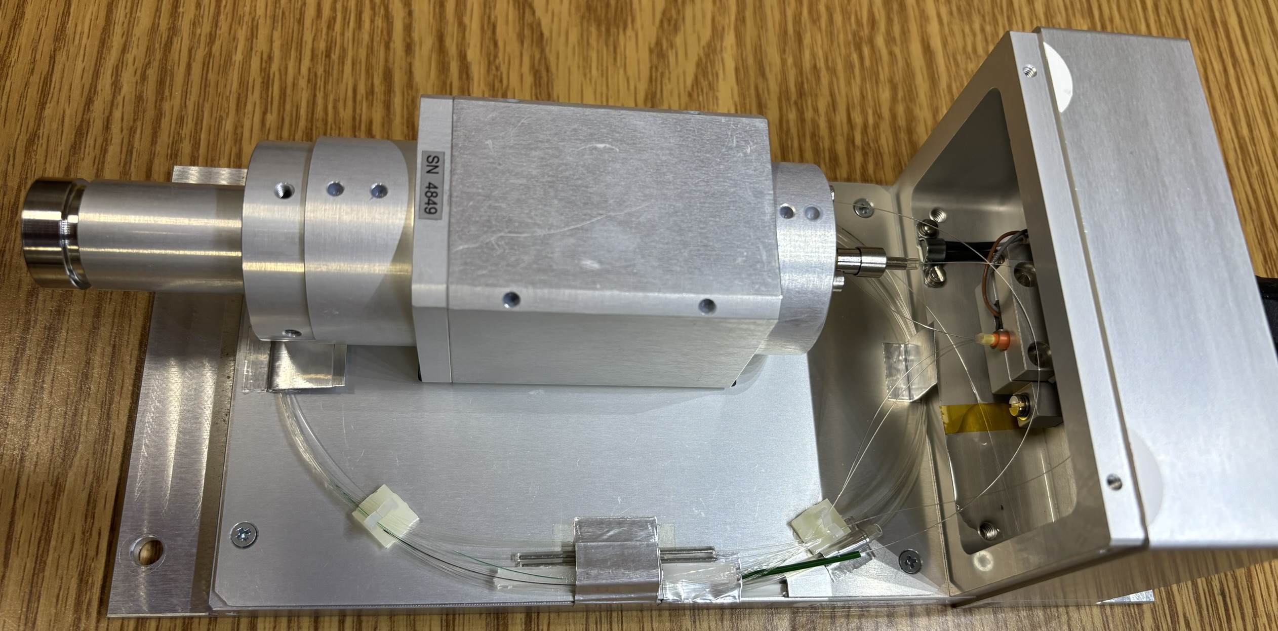
The laser head is an entirely passive device and contains no active circuitry. There are three strands of fiber contained within the yellow flex cable along with two copper wires for a thermistor mounted to the inside of the laser head casing. The fibers appear to all converge and terminate into a small sub-enclosure within the laser head. The sub-enclosure is sealed shut and can't be opened without risking damage. It likely contains beam shaping and filtering optics needed for the final output. These systems output an extremely narrow and high-quality beam of laser light. A few fiber fusion-splices are also visible inside of the laser head.
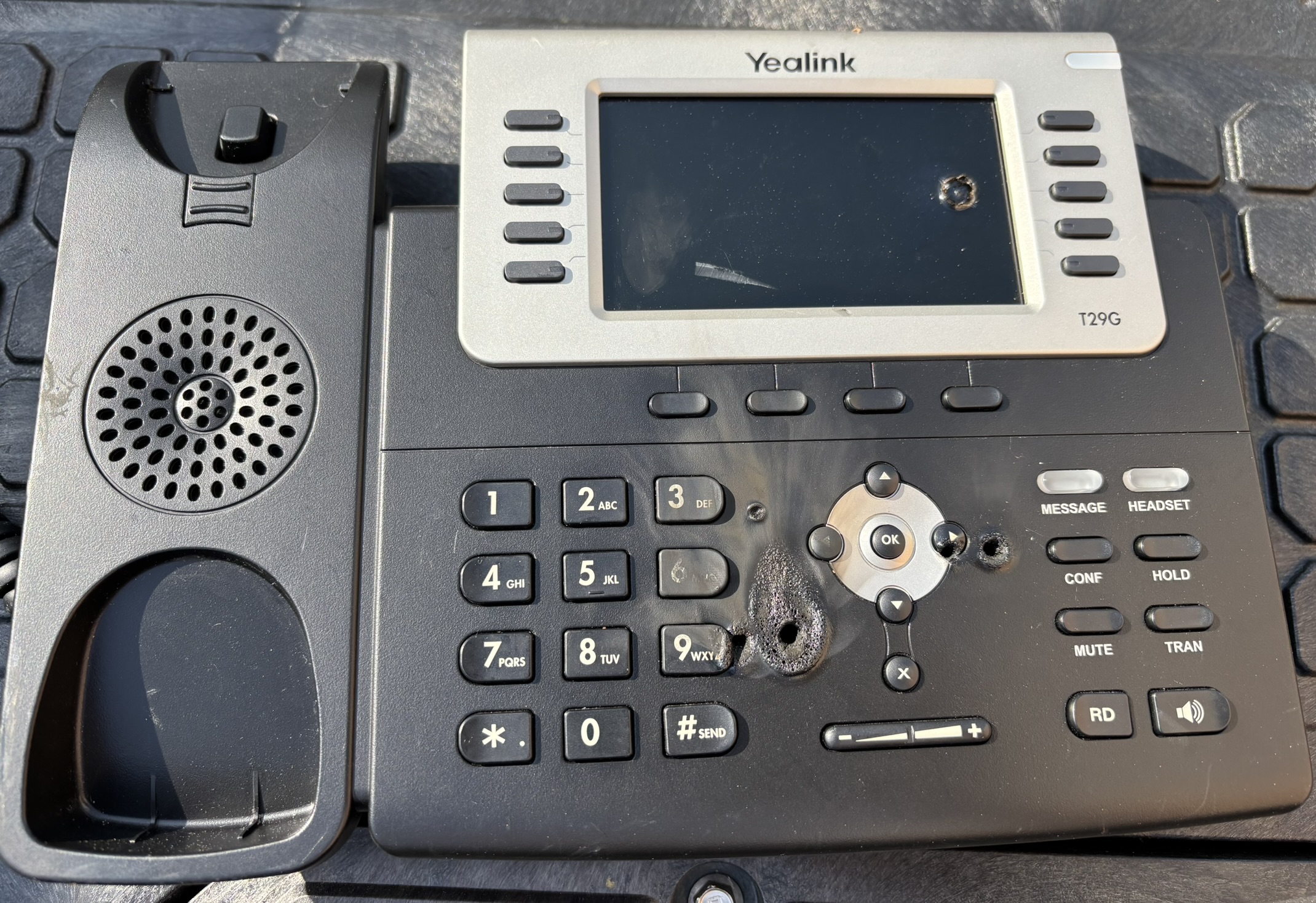
Since we weren't able to capture a good beam shot of this laser, enjoy the image below of a VoIP phone that was placed in the beam path to test the output power. Needless to say, it's a powerful laser and the phone is no longer in working condition.
Serial communication with this laser system was a bit of a challenge at first, since we were unable to locate an exact operator's manual for this particular system. However, we were able to reference manuals for similar systems and make educated guesses at other commands not in the manuals. Most importantly, the TX and RX pins on the RS-232 serial interface are reversed. You will need to use a crossover cable or adapter to establish serial communication. This isn't entirely uncommon, and is more evident by the use of a female DB-9 connector on the back. The female connector is usually found on the computer side, and the male connector is found on the device side, but this isn't a rule. See below for serial parameters and a list of known commands that we tested. Generally, read commands will start with the letter R and set commands will start with the letter S. The desired value should immediately follow the set command (example: "SCS50" for 50% setpoint). Refer to the YLR-200-AC manual for steps on how to interpret the return value of the STA (status) command as well as more information regarding serial communication.
- BAUD RATE: 57600
- DATA BITS: 8
- PARITY: NONE
- STOP BITS: 1
- FLOW CONTROL: NONE
| COMMAND | DESCRIPTION |
|---|---|
| RCS | Read current setpoint |
| SCS | Set current setpoint |
| RPW | Read pulse width |
| SPW | Set pulse width |
| RBR | Read back reflection |
| RHT | Read head temperature |
| RFV | Read firmware version |
| RBV | Read boot version |
| RCT | Read laser temperature |
| RET | Read elapsed time |
| RERR | Read system error(s) |
| RSN | Read serial number |
| RMN | Read model number |
| STA | Read system status |
| EMON | EMISSION ON |
| EMOFF | EMISSION OFF |