This is a Ytterbium pulsed fiber laser head manufactured by IPG Photonics in 2015. Unlike the other Ytterbium fiber laser we worked with, this is the head only, without the rack cabinet and additional control/interface electronics. It's a class 4 infrared pulsed laser with a maximum output power of 110 W (CW) and a staggering 110 kW peak power during pulsed operation. That is an intense amount of laser power, the danger of which is further magnified by the invisible wavelength. We expect it to be around 1064 nm like the other YLP-R unit. Needless to say, this is an extremely dangerous laser system. These types of lasers are typically used in industrial marking, etching, or even cutting applications. Based on the auxiliary interface board we received with this laser, we suspect it came from a piece of marking equipment manufactured by Telesis technologies. Telesis specialized in various laser marking systems capable of marking and etching various metals, plastics, glass, etc. An example use case for a system like this is for etching and engraving serial numbers and data matrix codes into metal vehicle parts.
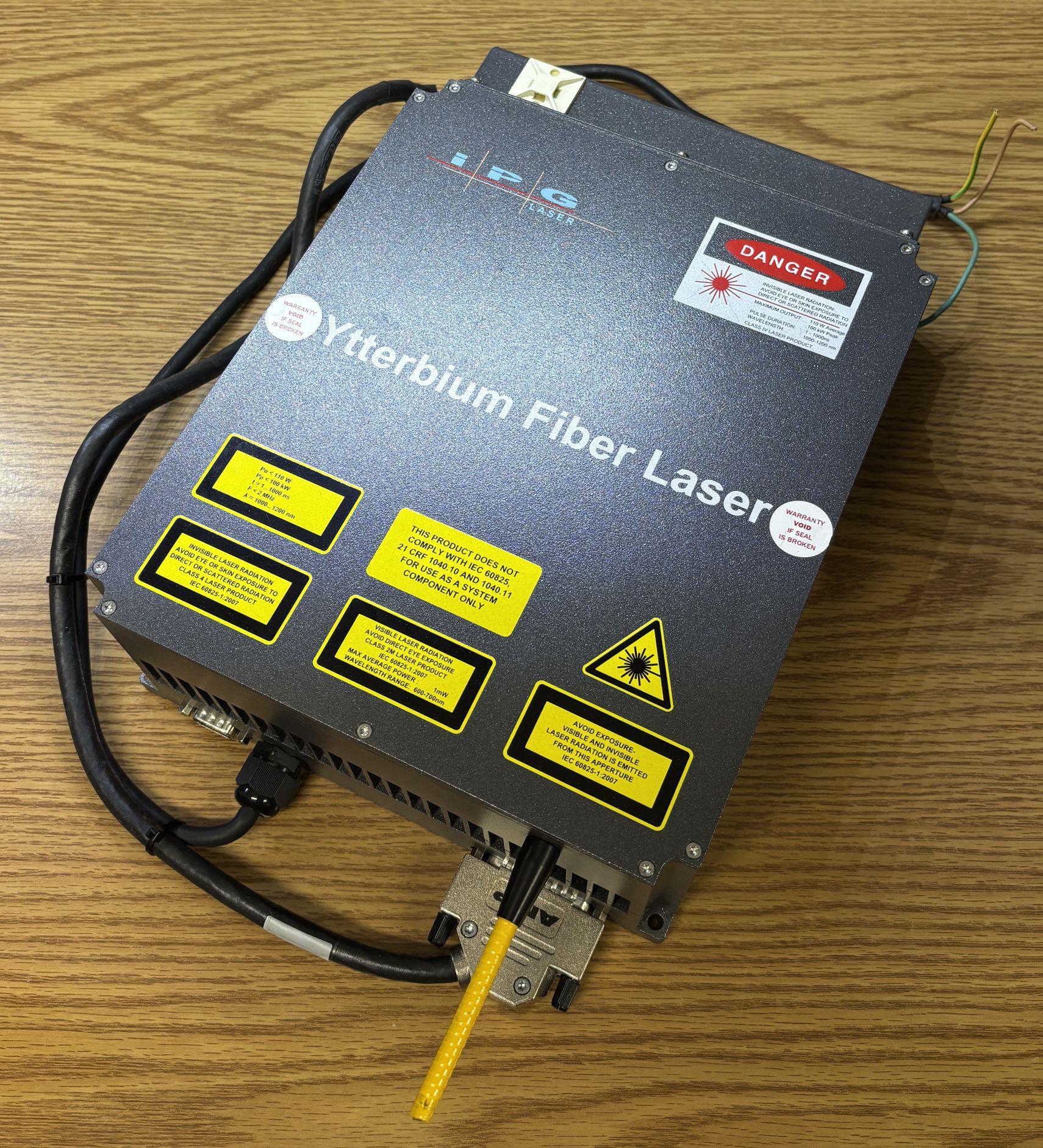
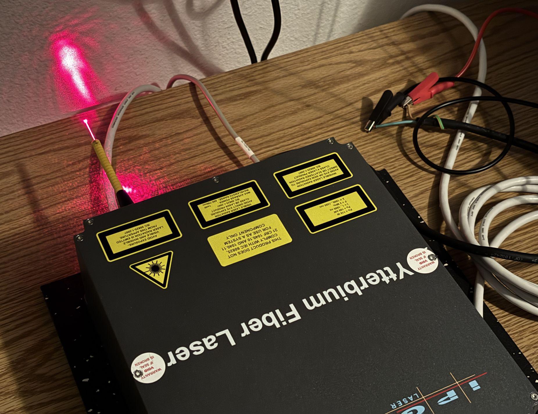
When this laser was pulled from service, someone committed the absolute sin of just cutting the jacketed fiber cable with a set of side cutters. This isn't unrecoverable, but it would take significant effort to re-terminate the fiber into a lens or fusion splice it to another length of fiber, something we may attempt in the future. Because of this, the beam output is not properly collimated and angles downwards from the end of the fiber. Other than testing and demonstration, the system should not be used like this, damage to the fiber could occur during prolonged use at higher power levels.
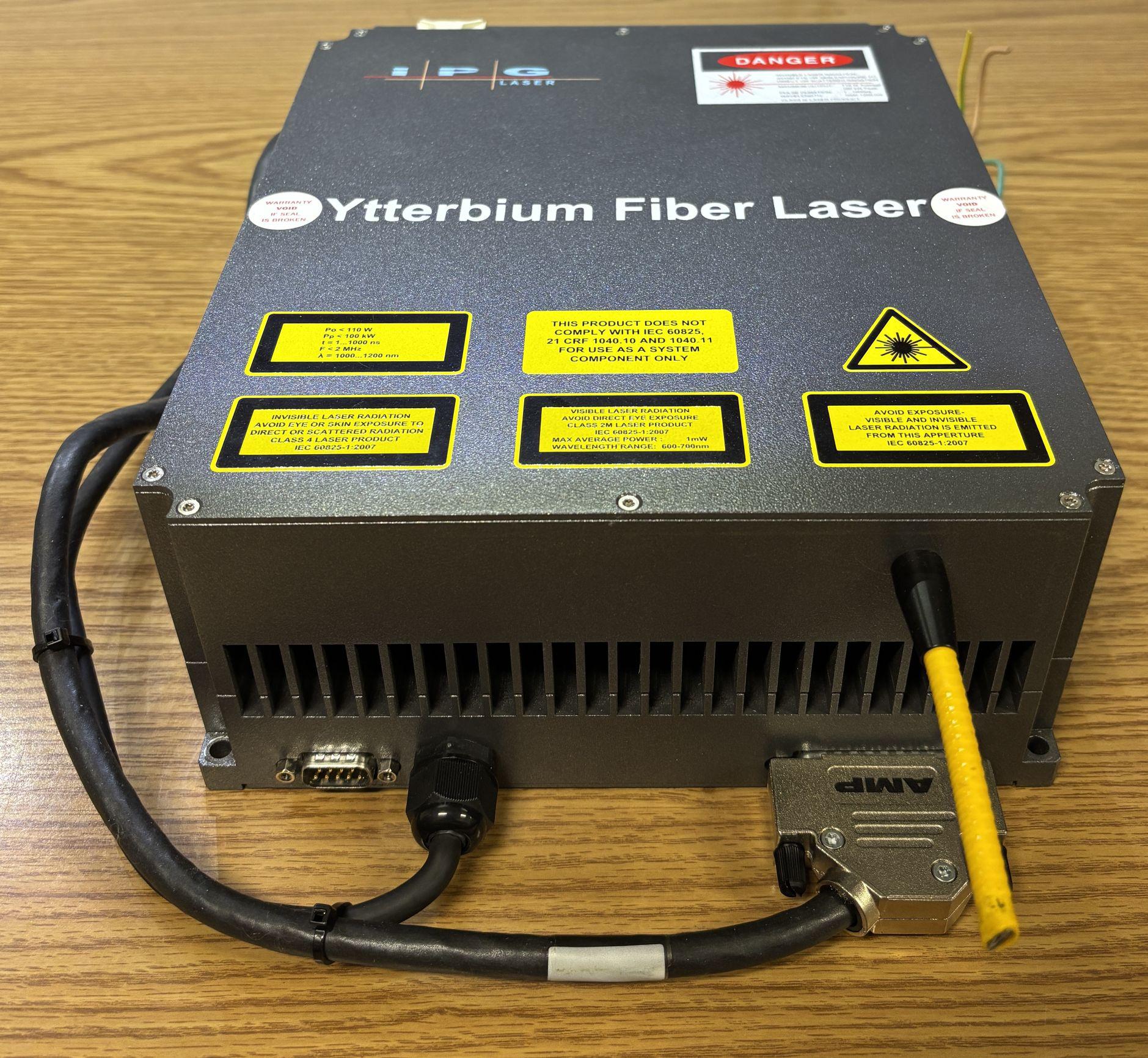
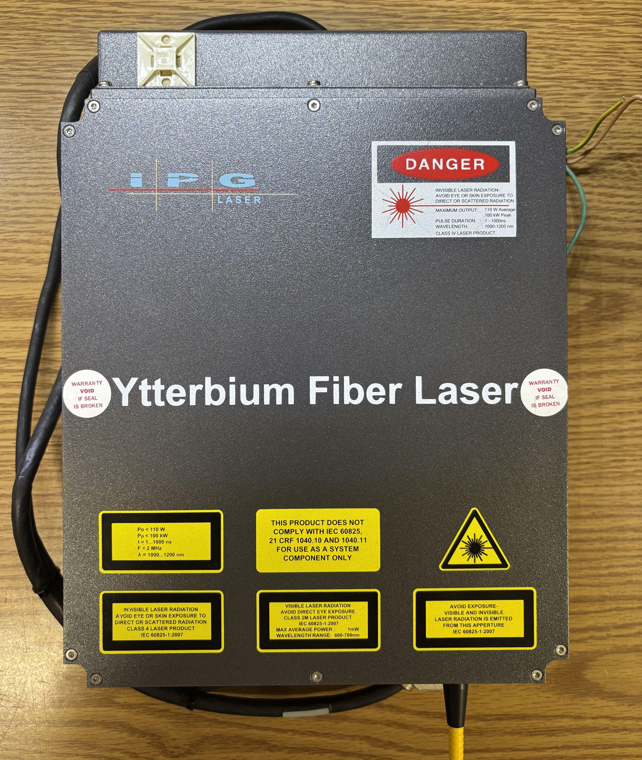
There's not much notable on the top aside from a combination of class 2M and class 4 laser safety warning labels. The metal top is secured to the case by 12 torx screws. Under this cover are the passive optical components that we'll discuss later along with two pump diodes.
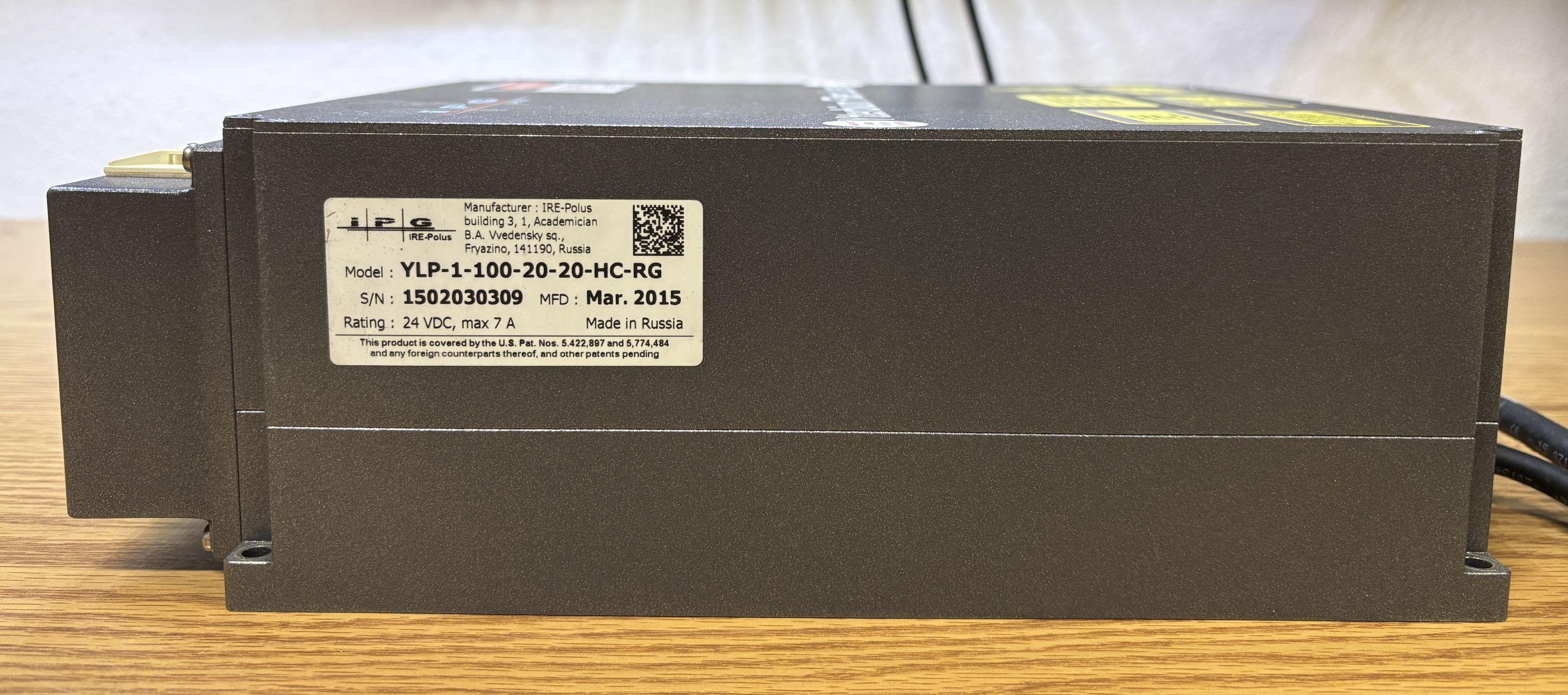
On the side of the laser is an information label that lists the part number (YLP-1-100-20-20-HC-RG), a manufacture date (March, 2015), voltage rating, and serial number. This is a surprisingly modern product to be made in Russia but sold in the US. The system is powered by 24V DC and can draw a maximum of 7 amps.
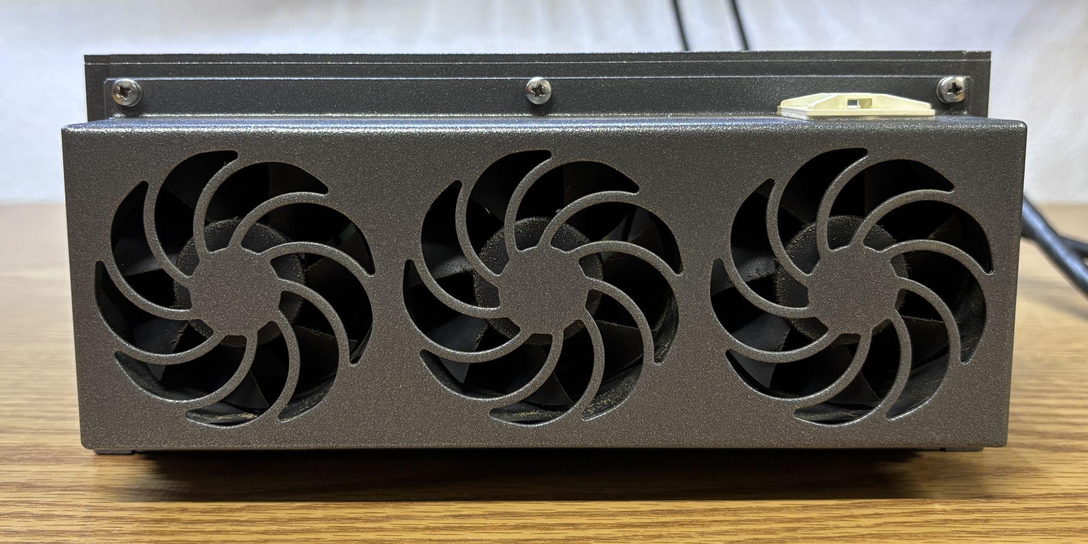
Three fans on one side of the laser pull air through the entire chassis, which acts as a heatsink for the electronics and laser diodes.
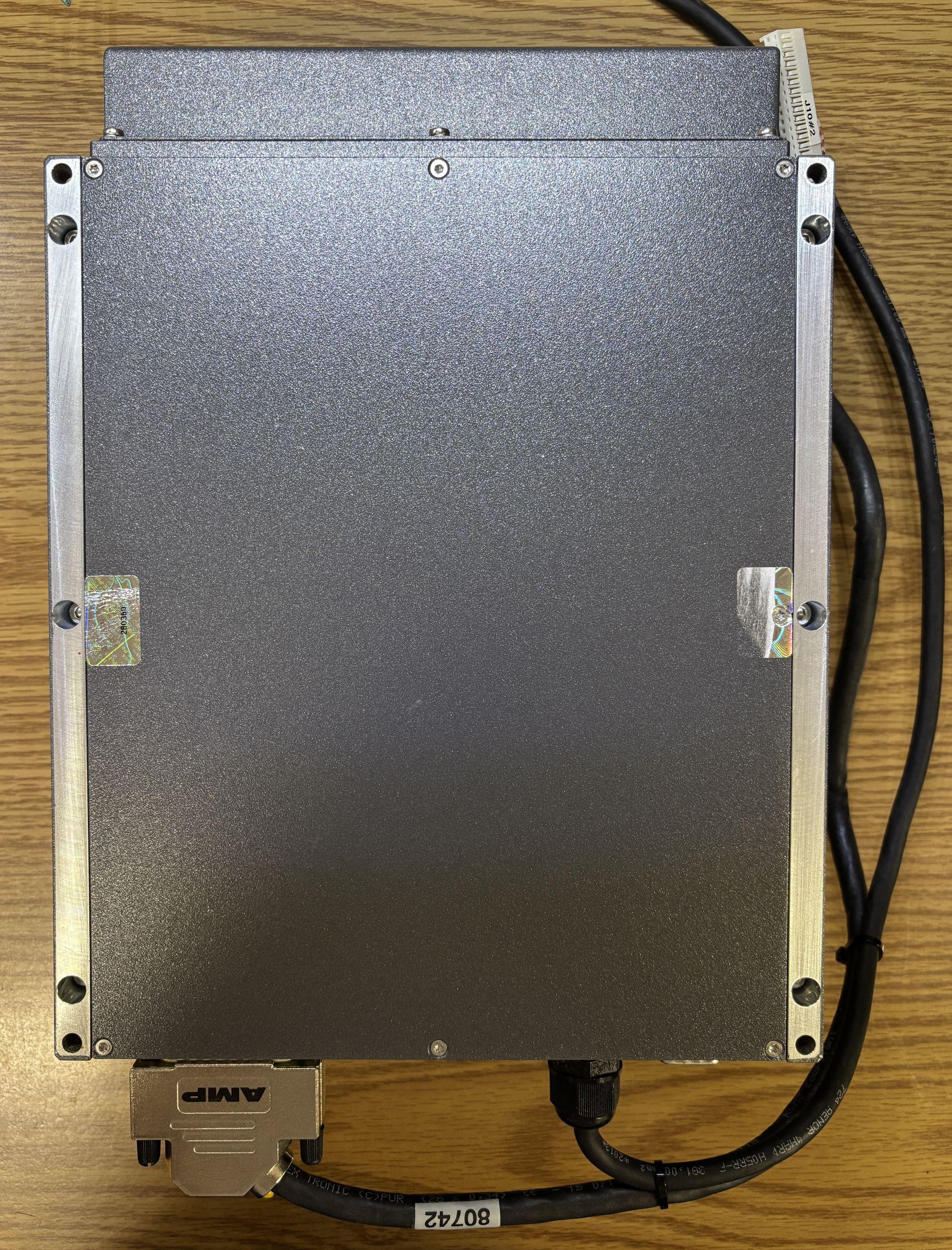
On the bottom of the unit is another cover that can be removed to reveal the electronics and control board.
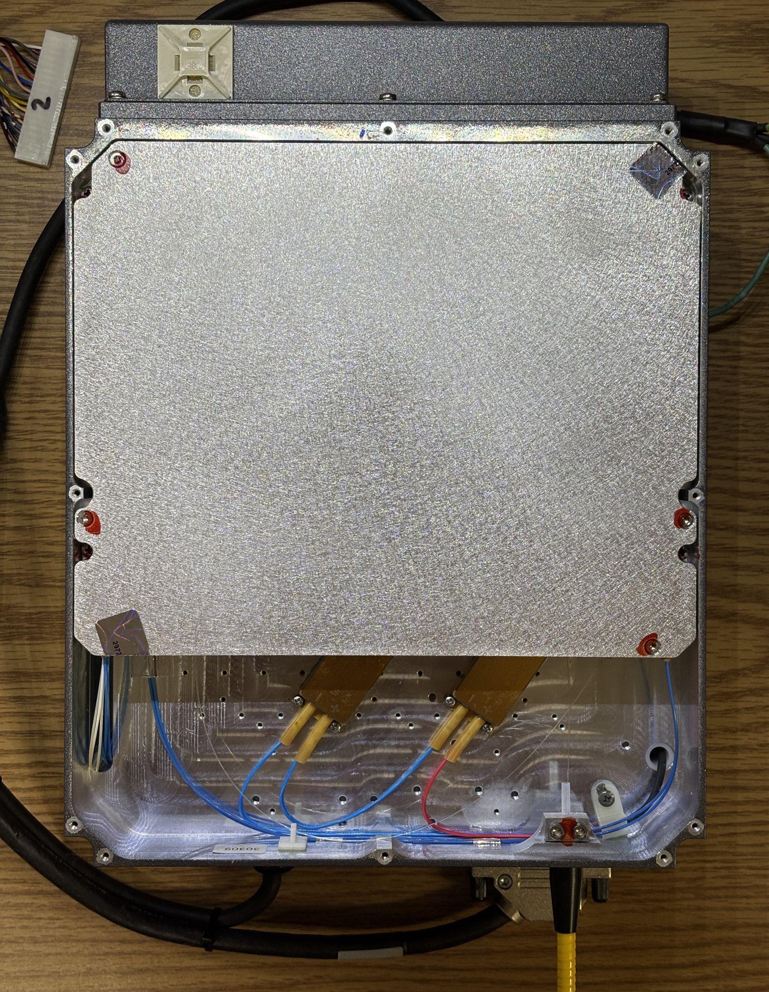
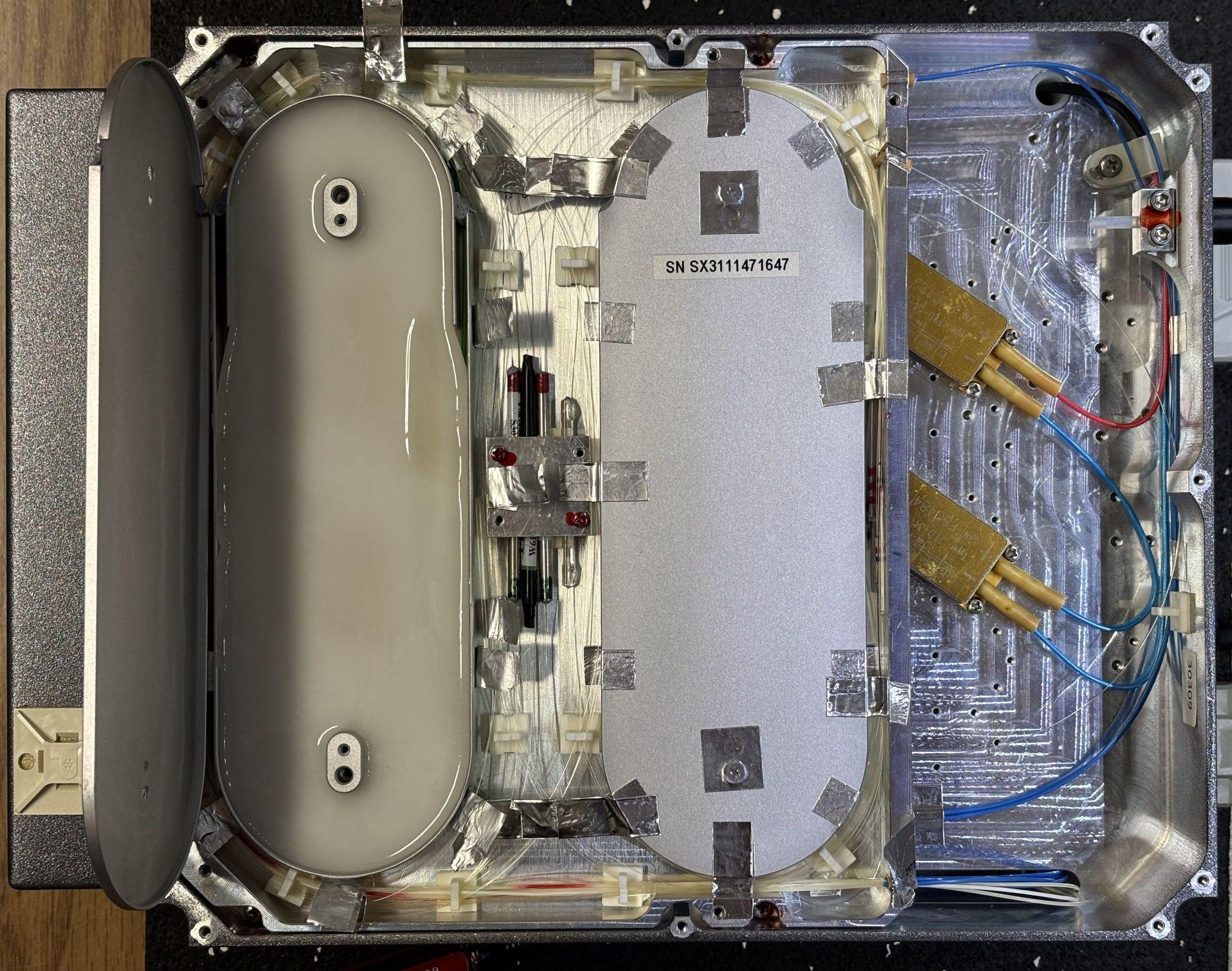
Below the top cover is the fiber assembly and two large pump diodes. We can also see how the jacketed fiber attaches to as passes through the case. It should be possible to replace the hardened jacket and re-splice the fiber to restore this unit to a fully operational status. Luckily, there is sufficient extra length of fiber within the enclosure to facilitate re-splicing.
Opening the fiber assembly cover reveals a complex arrangement of several fibers all wound around two metal enclosures. The fibers are joined in the center through what we presume are fusion splices with protective covers. This solid-state laser uses ytterbium-doped optical fibers as the gain medium. The process is similar to how nonlinear crystals work, but fiber lasers have several advantages that include higher reliability, longer lifespans, and less required maintenance. Additionally, much higher power levels can be achieved by following the MOPA (master oscillator and power amplifier) scheme which uses a "seed laser" as the master oscillator, essentially setting the stage for the gain medium. Pump diodes are used to send energy into the ytterbium-doped fiber. As the Ytterbium ions absorb the energy, they become excited and reach a higher energy state. The end product, which exits from the fiber, is an amplified amount of laser light in the infrared spectrum. Common output wavelengths include 1030, 1040, and 1064 nm. This arrangement also is better suited for laser systems that require very short pulses, such as high-end femtosecond lasers.
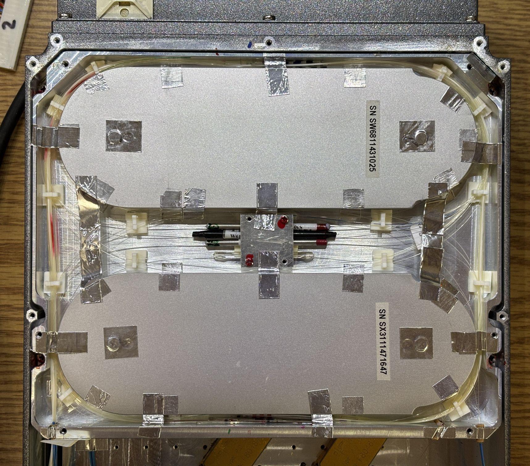
Here is a closeup of the splices and protective covers, which also have part numbers, likely used to identify the variant of doped fiber.
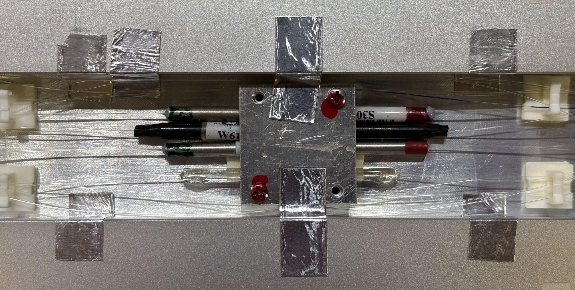
We carefully removed the top cover of one of the fiber enclosures, only to be met with milky white potting compound. It's quite soft and pliable, but fully obscures whatever fiber laser "magic" is going on in there. It is also possible that the compound is used to dissipate and transfer heat from the fiber components to the outer enclosure. Since this unit is functional, we decided not to dig out the potting compound as it would likely destroy the laser.
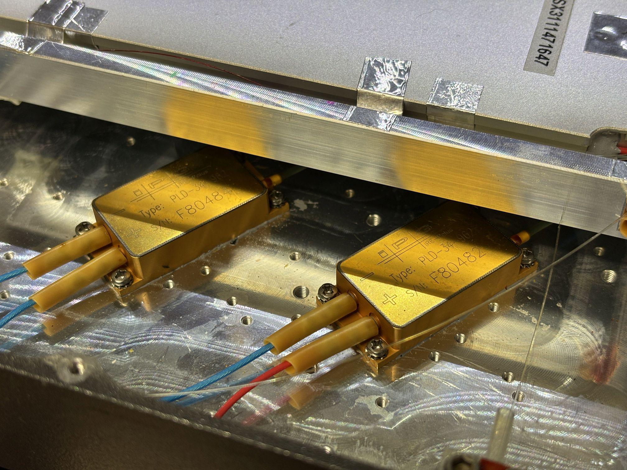
Here is a closer look at the pump diodes, manufactured by IPG and wired in series. They are both PLD-34-962 with a wavelength of 962nm and a maximum output power of around 34 W (assuming these diodes follow IPG's naming convention).
The edge of the optical fiber assembly was covered in thermal paste, and is secured to the outer casing by several screws. It's hard to imagine optical fiber heating up significantly, but perhaps it was a concern with this type of laser since it uses these specialized doped fibers.
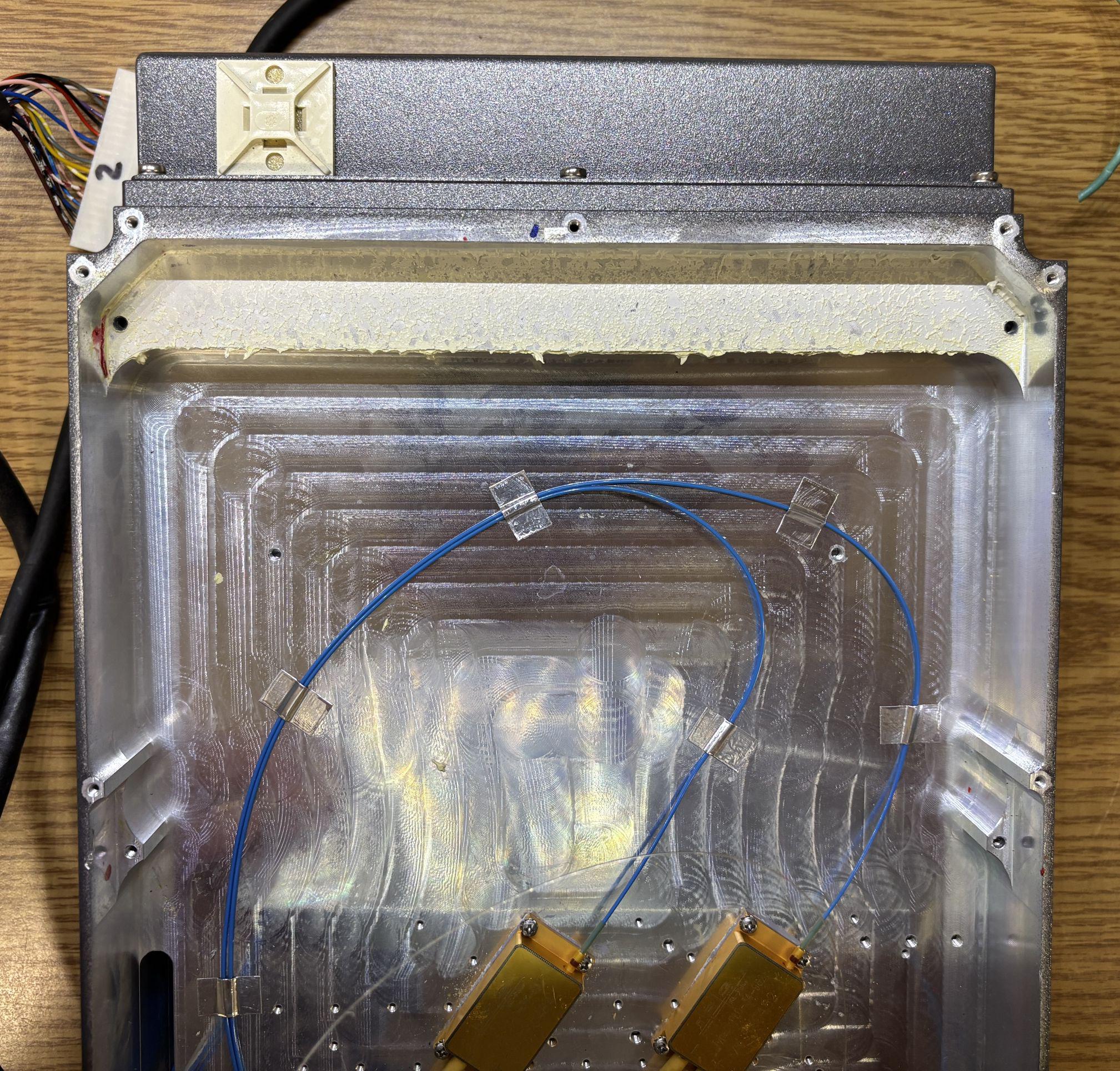
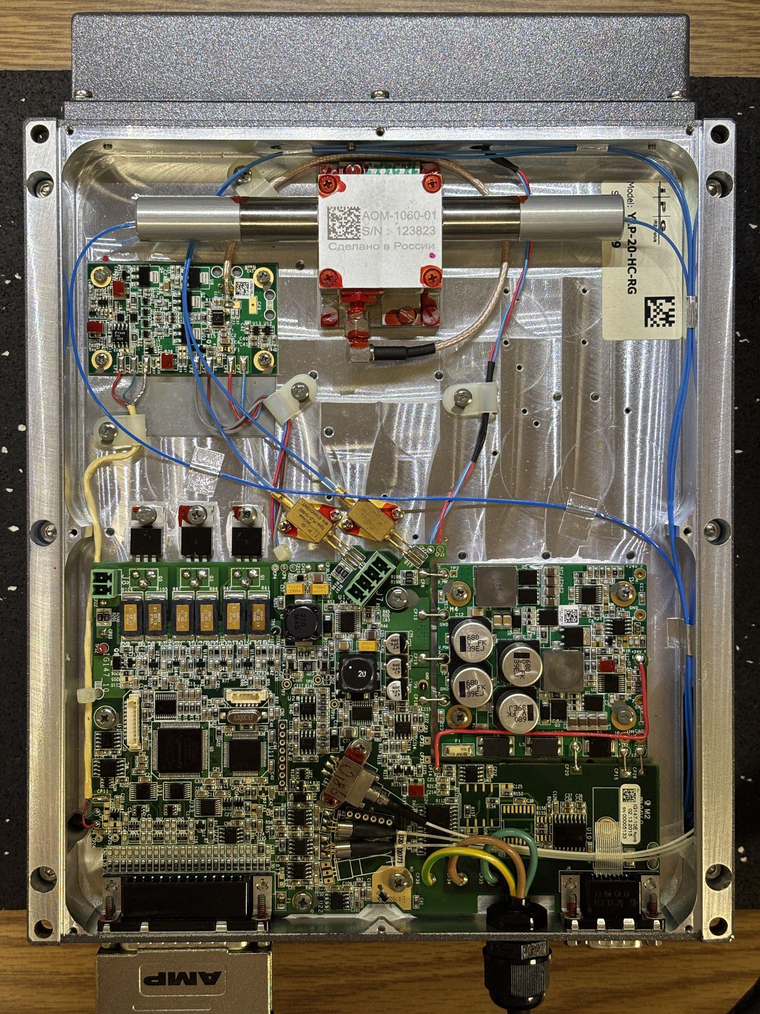
Removing the bottom cover reveals the main control board, additional laser diodes, and the q-switch. The square enclosure on the top with cylinders on either side is the acousto-optic modulator (AOM), also known as a q-switch. It has a part number of AOM-1060-01 and was also made in Russia. We speculate that this laser has an output wavelength of 1060 nm based on the AOM's part number. The AOM is responsible for the pulsed aspect of this laser system and according to the firmware, has a user-defined range of 20-200 kHz. The AOM uses a piezoelectric optical element that is excited by an RF signal. Based on the excitation, it either passes or blocks light. The RF generator board is located below and to the left of the AOM. This arrangement is used to achieve extremely fast pulses of laser light and is also used to amplify the output power. The two gold packages above the control board are the seed laser diodes. They have permanently-attached fiber pigtails that go through an opening to the other side of the enclosure. There are no free space beams inside of this laser head, everything is fiber-coupled. The digital control board uses an Altera Cyclone as the main MCU along with several other digital components. On the right side of the DC-DC converter. Even though it looks like and AC line cord, this system required 24V DC and steps it down internally as needed. Other notable components on this board include the DB-25 connector for digital I/O and control, DB-9 connector for the RS-232 serial interface, two photodiodes for monitoring, and the aiming beam laser diode and mount (metal package with 981 handwritten on it, LD1 on silkscreen). There are several diagnostic and debug headers on the board worth probing. We also did de-solder and read out the EEPROMs, but found nothing of value. These lasers would be a good candidate for an aftermarket or open-source control board since there are no temperature-sensitive crystals to deal with, just laser diodes and the q-switch.
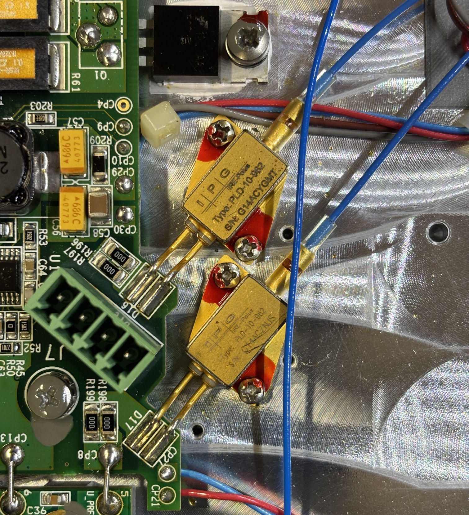
Here is a closer look at the seed laser diodes. They are IPG PLD-10-962 laser diodes with a wavelength of 962 nm and a maximum output power of 10 W. Their leads are soldered directly to the control board and there appears to be a test jumper located right next to them.
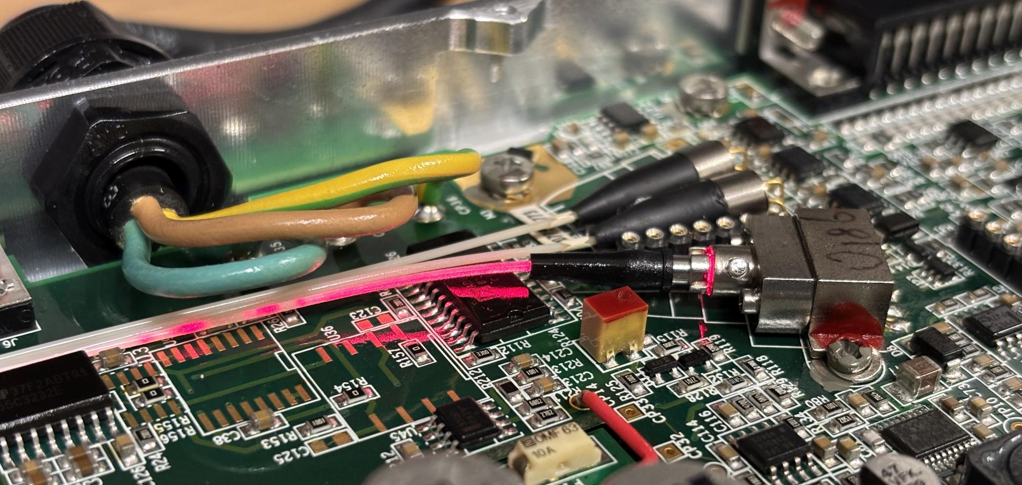
In the image below, a bit of light is visible from the guide laser diode mount and also illuminates the shell of the fiber. The output power of the guide laser is so low that this isn't really an issue.
Getting this laser up and running was a bit of a challenge. The interface specification manual had some conflicting information was further complicated by the fact that this laser rejected the majority of commands sent to it. Even though these lasers are supposed to be fully controllable over the RS-232 interface, this one only responds to signals from the DB-25 I/O connection. This laser came with a 3rd party control board that mates with a wire harness that connects to the DB-25 port on the head. Not every connection is passed through, only the essentials.
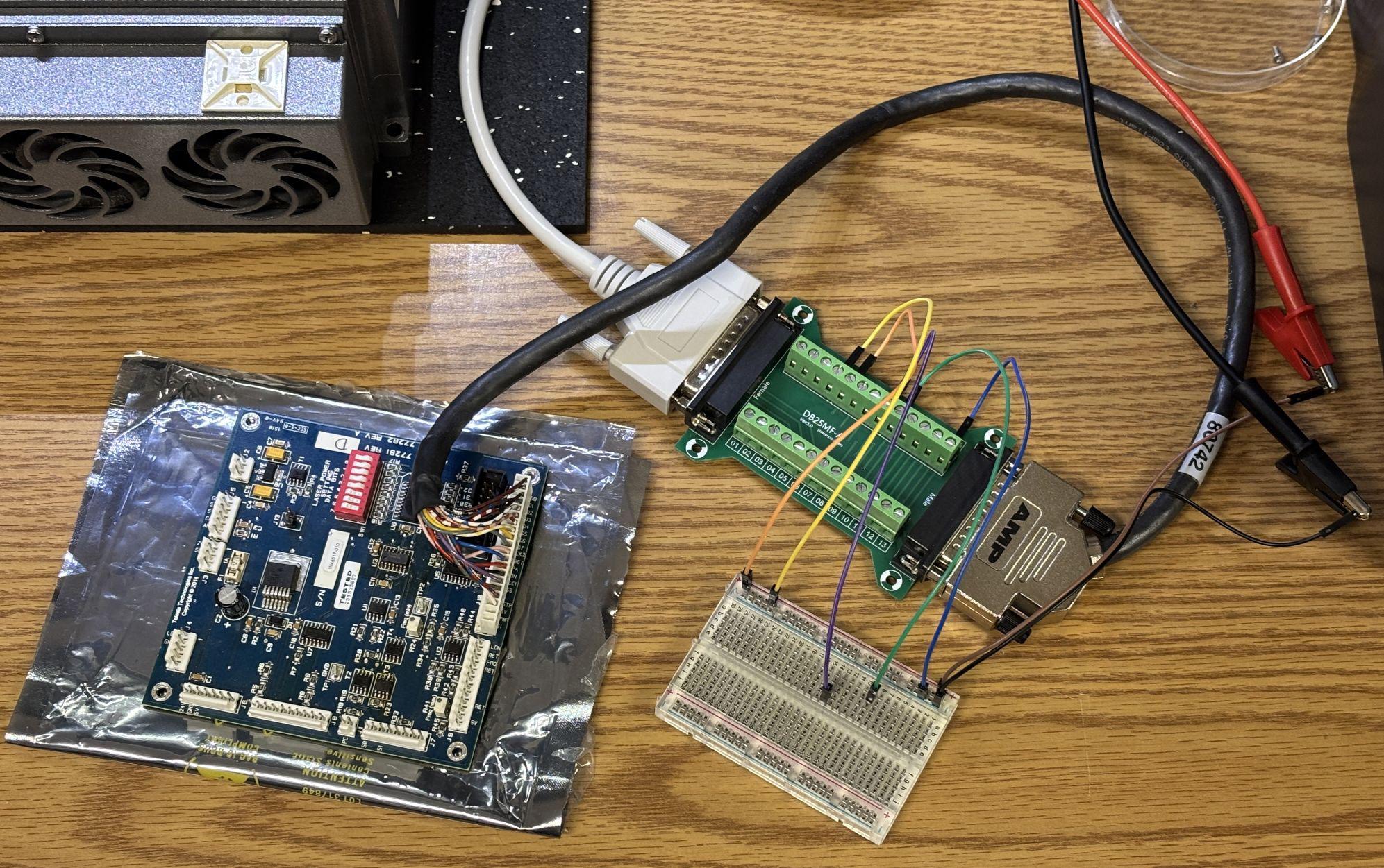
The manufacturer of the board is Telesis Technologies, which gives us a good hint as to where this system came from. This was their custom interface that allowed the IPG laser head to be integrated into whatever laser marking or cutting system it was intended for. This board is not strictly needed to operate this laser, but we kept it solely for the purpose of adjusting the laser power setting data bits. The bank of DIP switches allow this to be adjusted, which can then be verified in software. If you don't have this board, it's no big deal, just reference the interface specification manual for setting the laser power bits and latching the setting.
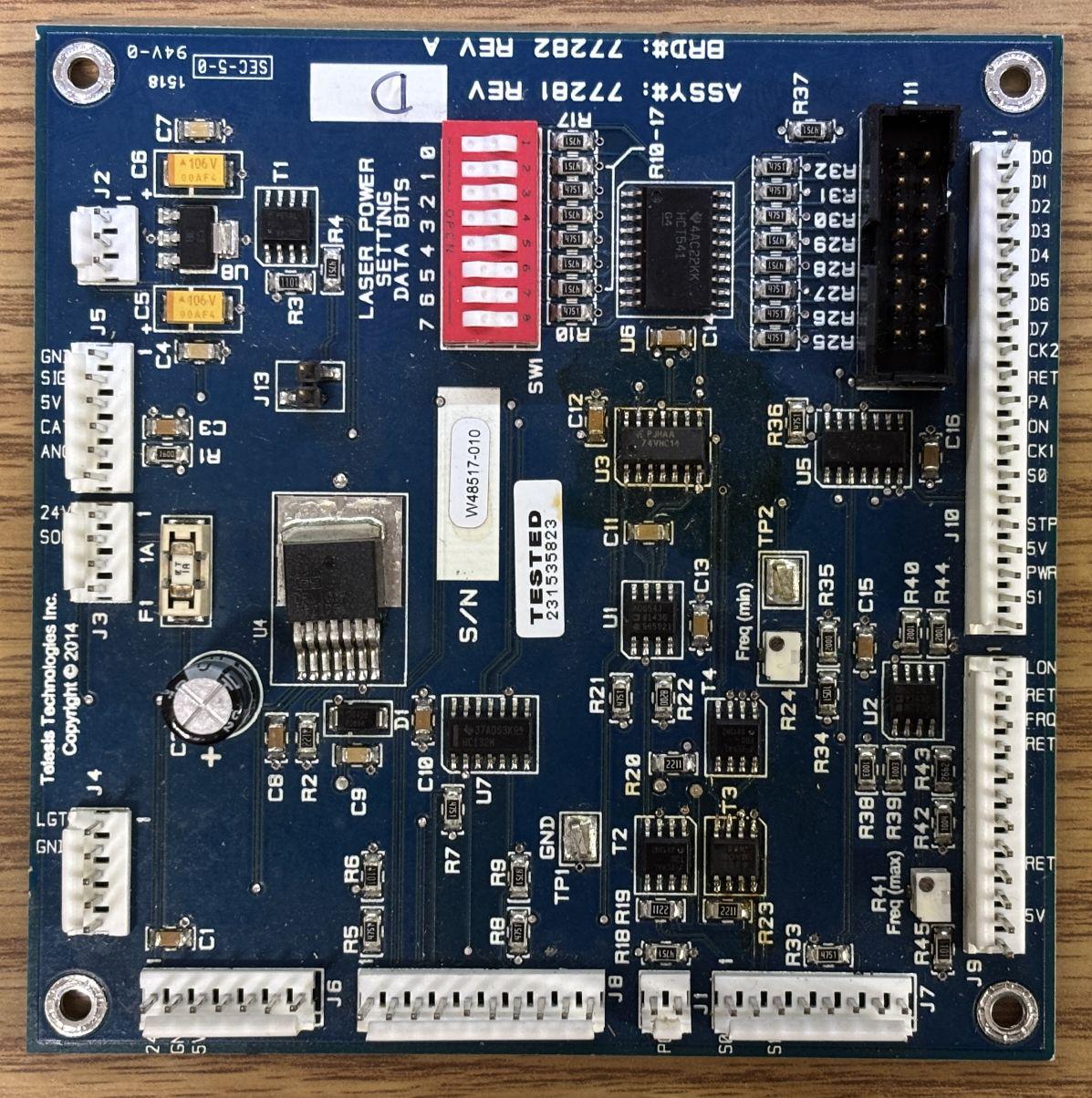
An abbreviated pin-out for the DB-25 connector of this laser has been provided below. Refer to the PDF document (type E interface specification) for a full pin-out.
| PIN | DESCRIPTION |
|---|---|
| 1-8 | 8-bit laser power setting |
| 9 | Laser power setting latch |
| 14 | Ground |
| 15 | 5V output |
| 17 | 5V output for independent operation of guide laser |
| 18 | Emission enable signal (high = enabled) |
| 19 | Emission modulation input (high = emission on) |
| 20 | Sync / pulse repetition rate input |
| 22 | Guide laser control input (high = guide laser on) |
| 23 | AuxOFF / interlock (high = laser enabled) |
After a bit of trial-and-error we got the laser to fully power on and emit a beam of infrared light. It even burned some electrical tape despite the chopped fiber! The following connections are required to enable emission, and the order does matter. The pins are TTL inputs and we found that the internally supplied 5V rail did not work, and had to supply 5V externally to pull the required pins high.
- 1. Apply 24V DC power to the system
- 2. You will need to pull pins 18 (emission enable), 19 (emission modulation), and 22 (guide laser enable) LOW initially, using pin 14 as ground
- 3. Pin 23 is the AuxOFF / interlock and needs to be pulled HIGH for the laser to function
- 4. Use pins 1-8 and 9 to set the desired output power level
- 5. Pull pin 18 HIGH to enable emission, this will enable the pump diodes at idle power level
- 6. Pull pin 22 LOW to disable the guide laser, otherwise the system will not output infrared laser light
- 7. Pin 19 can now be pulled HIGH as needed to activate emission at the configured power level (remember to use protective eyewear)
- 8. Pulling pin 19 LOW stops emission and places the diodes back at idle
- 9. The guide laser can be enabled at this point if needed by pulling pin 22 HIGH
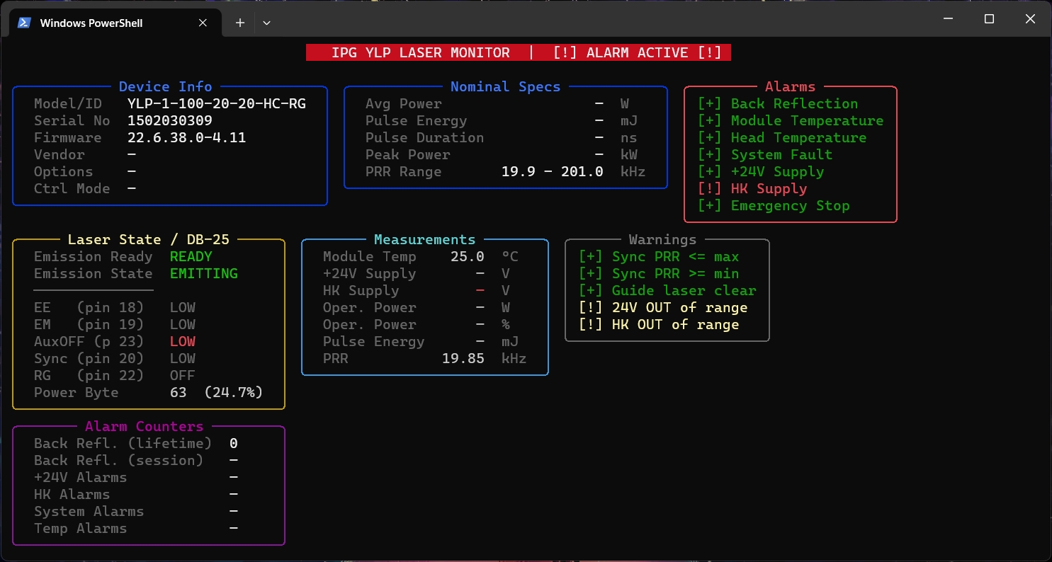
Establishing serial communication with this laser is somewhat straightforward. First, you will need a null-modem or crossover cable when connecting to the RS-232C serial port. The serial connection parameters are as follows: 57600 baud rate, 8 data bits, 1 stop bit, no parity, no flow control. After that, the most important thing to remember is that each command must be prepended with a $ or it will be rejected or the laser may not respond at all. The interface specification document explains this and also mentioned the use of a semicolon after each command, but we have found that the semicolon does not seem to make a difference. The end result is no different whether it's used or not. The laser will not echo commands back, it will only return the result or an E for error or N for rejected command. We have found that our laser rejects many of the commands listed in the specification document. We have seen this behavior with other IPG lasers and assume it has to do with the lasers being heavily customized for their application or OEM installation. A table of commands that work with this specific laser is provided below.
| COMMAND | DESCRIPTION |
|---|---|
| $1 | Read device ID |
| $2 | Read serial number |
| $3 | Read firmware version |
| $4 | Read device status |
| $5 | Read device temperature |
| $10 | Read digital interface status/td> |
| $11 | Read extended status |
| $12 | Read back reflection counter |
| $18 | Read pulse repetition range |
We wrote a simple Python terminal user interface application to display the laser's status while we worked on it. This proved to be quite helpful when setting the output power. The program only queries the laser for status, it does not attempt to send any control commands since this laser rejects all control commands sent over the serial interface anyway. There are a few quirks and erroneous warnings since this laser does not exactly follow the specification outlined in the document, but the important parts work fine. You can download this program using the link at the bottom of this page.
In the image below, only the red guide laser is enabled, the image was exposed for longer than usual, making the 5 mW red laser look abnormally bright and vibrant.
For a full list of serial commands, a pin-out, and other specifications applicable to this laser, check out the document linked below. We have also included a link to download our custom Python program that displays laser status in the terminal.