We built this laser controller out of necessity when we first got our hands on the Melles Griot 35-IMA-830-012 Argon Ion laser system. It's intended to be used with Melles Griot 175B/176B/300 series power supplies and the IMA series argon ion laser systems. The power supply features a DB-25 connector with an assortment of I/O. If you just want to to get the laser running, you don't really need a controller, the project page for the 35-IMA-830-012 laser system explains which pins on the DB-25 connector need to be connected to get the unit lasing. Having a full controller is helpful to view the tube current and laser power reading as well as easily switch between operating modes. OEM controllers are available for these laser systems but are hard to find and often expensive, which is why we built our own. Click the link below to visit the project page for that laser system.
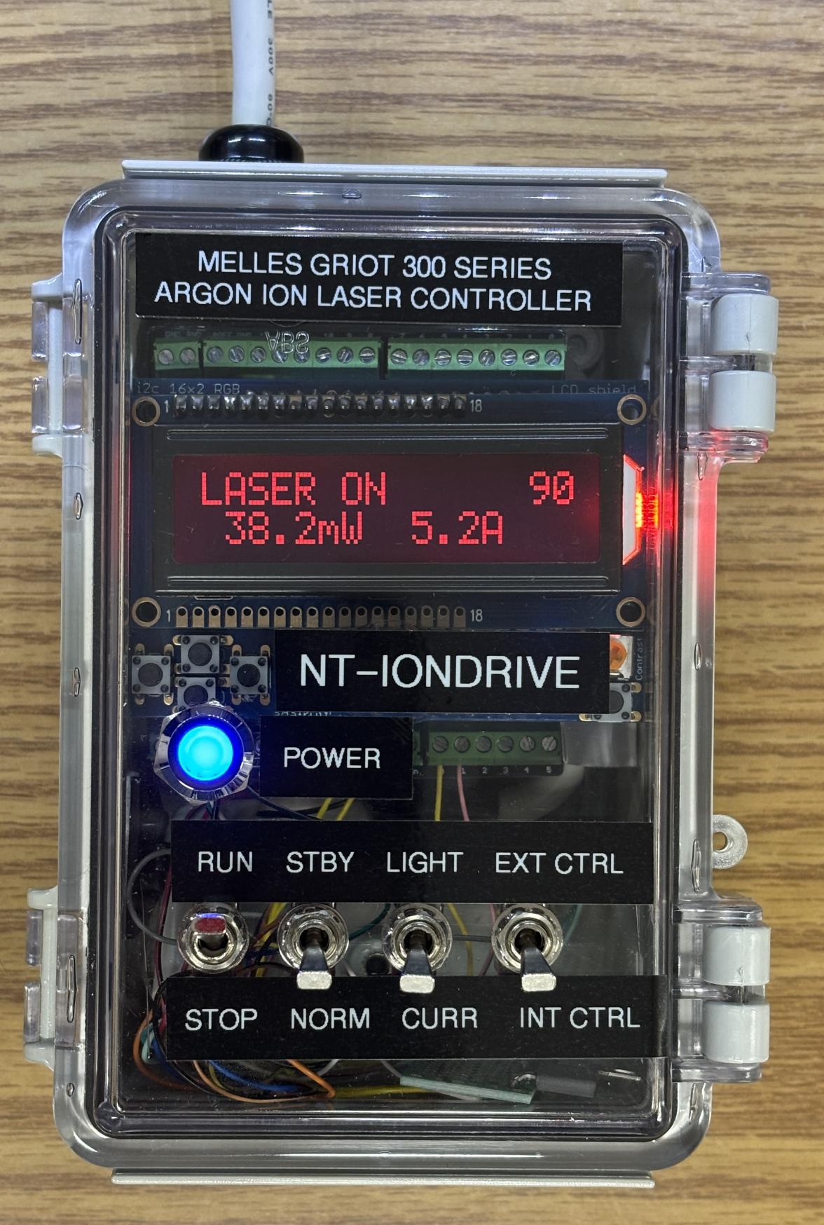
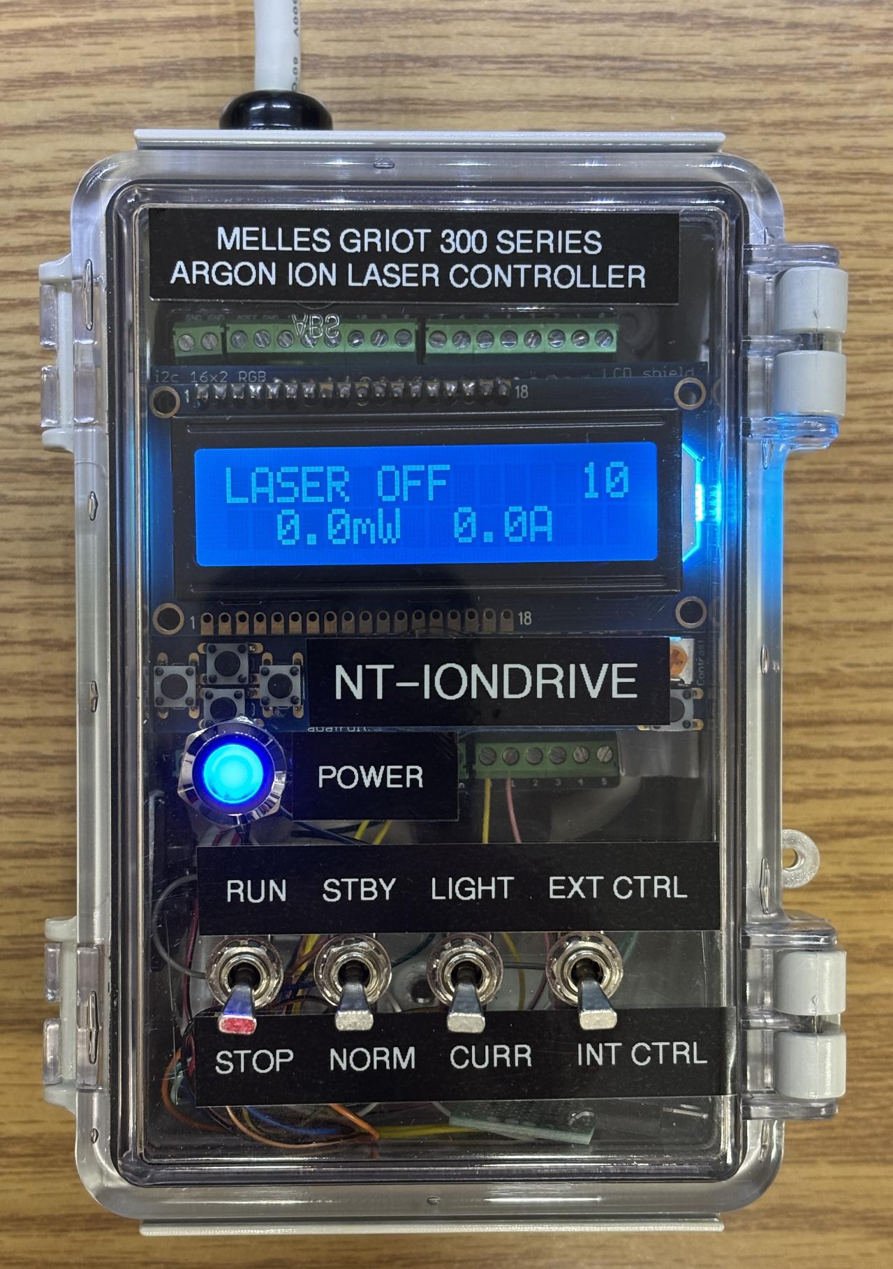
The controller casing is a small plastic, waterproof box with a transparent hinged door. We drilled some holes to route a chopped up DB-25 parallel cable which serves as the connection to the laser system power supply. Using the known pin-out, we connected the interlocks as well as the mode selection pins to some toggle switches mounted on the door of the box. These allow the operator to easily open/close the interlock and thus enable/disable the laser. Additional switches allow the operator to change from current control to light control mode, enable standby mode, and even switch from internal control (using the power supply potentiometer) to external control. This is much easier then moving jumper wires on the DB-25 connector. There is also a power LED that illuminates when the power supply is on and the controller is connected.
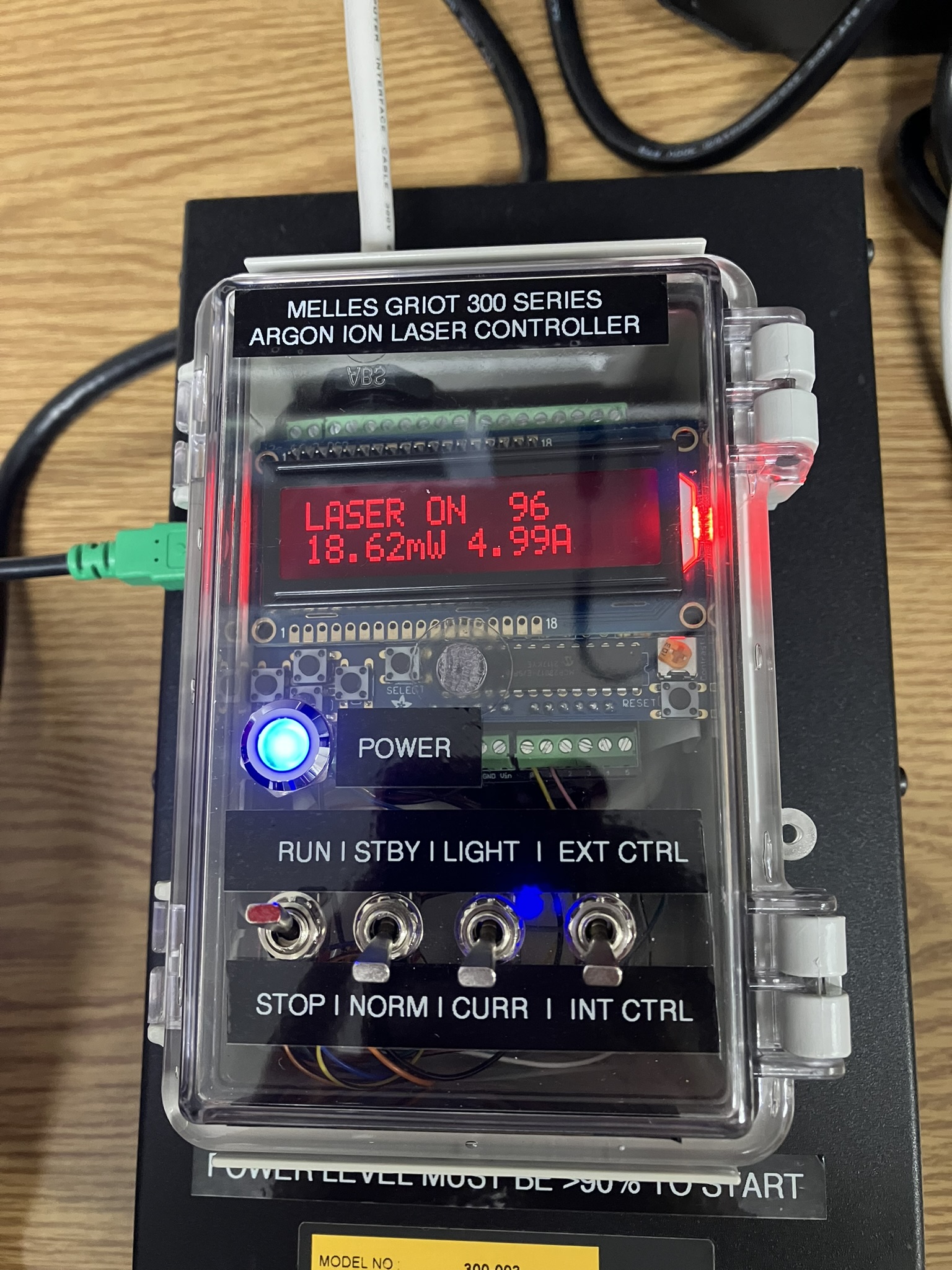
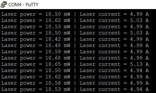
This controller is based around an Arduino that reads the voltage from the pins of the DB-25 connector for tube current and laser power. Using software, it scales these values and displays them on the LCD screen and outputs them over a serial interface for use with a computer. It also allows for different scale factors to be chosen based on the laser system it's connected to.
Eventually, we plan to add functionality to this device to allow it to control the interlock and tube current setting so a classic argon ion laser can be computer-controlled.
Below is a screenshot of the serial output from this controller, which includes tube current and laser power.