The Coherent Genesis CX 355-20 is an ultraviolet laser system with a maximum output power of 20mW. It produces invisible UV laser light at a wavelength of 355nm, using OPSL technology. Compared to our other OPSL lasers, it's quite a monster as far as physical size and weight, but this unit in particular has a relatively low max output power. Out unit arrived in good condition and is fully functional. We disassembled the laser head and power supply for examination and to take pictures for this write up. It has low hours and produces the full 20mW of laser power without any issues. We are unsure of the original use case for this laser system, but as with most lasers we work with, it was probably used in some sort of scientific application.
Since UV lasers like the Genesis 355 produce light outside of the visible spectrum, you cannot see the laser beam or dot with just your eyes. You must exercise extreme caution when working with lasers that operate outside the visible spectrum, as you will not be able to see the beam and where it's directed. Never assume a laser is not working and safe if you don't see the beam. It could be producing a significant amount of invisible UV or infrared light, which can still cause severe eye damage. Placing any fluorescent material in the beam path will immediately make the beam visible. In the image below, a sheet of copy paper reveals a bright blue dot. This is not a representation of the laser's wavelength, it's just the color emitted by the fluorescent component of the paper when excited by the UV laser light. Other fluorescent materials will emit different colors of light and are fun to experiment with!
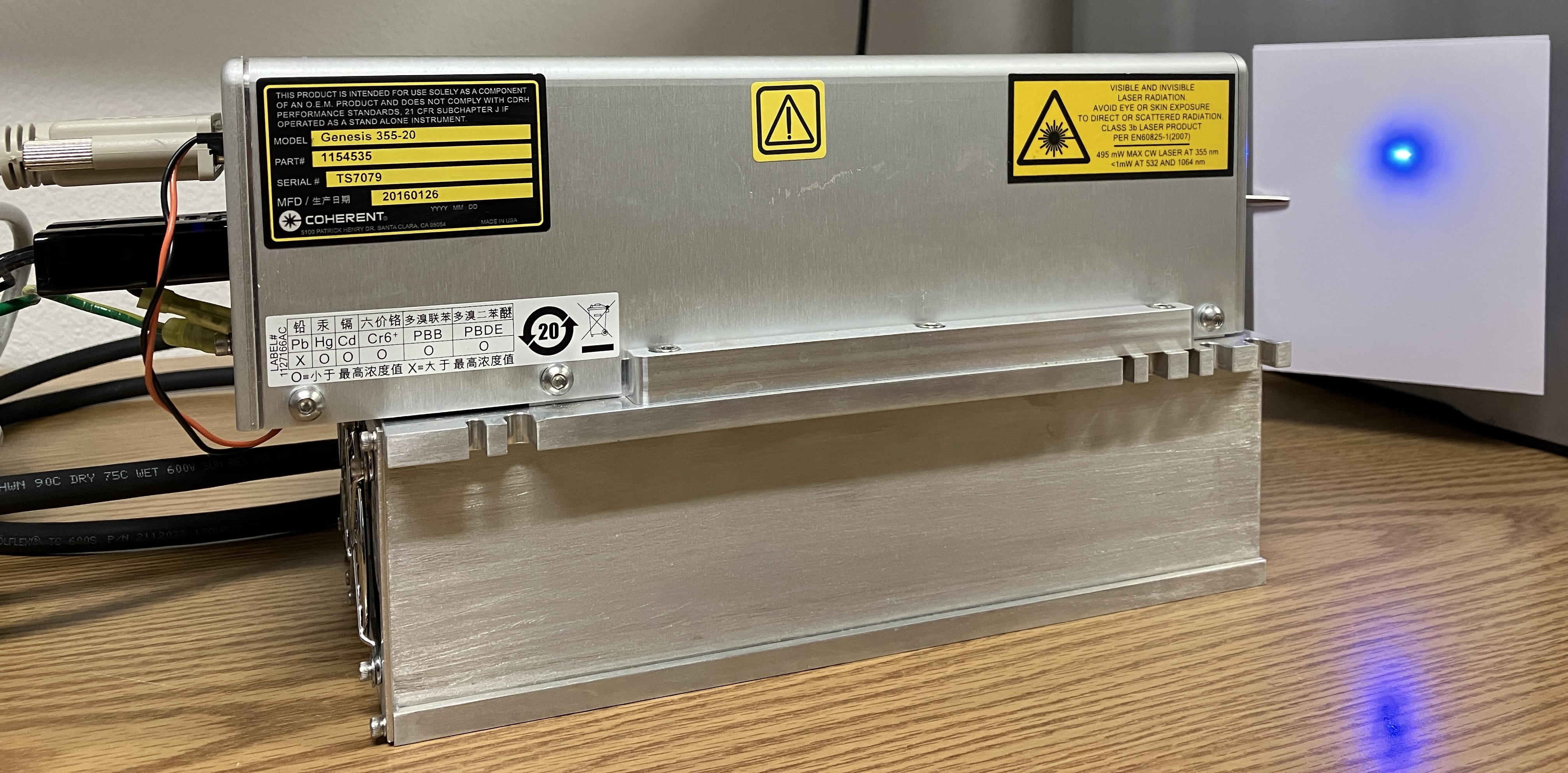
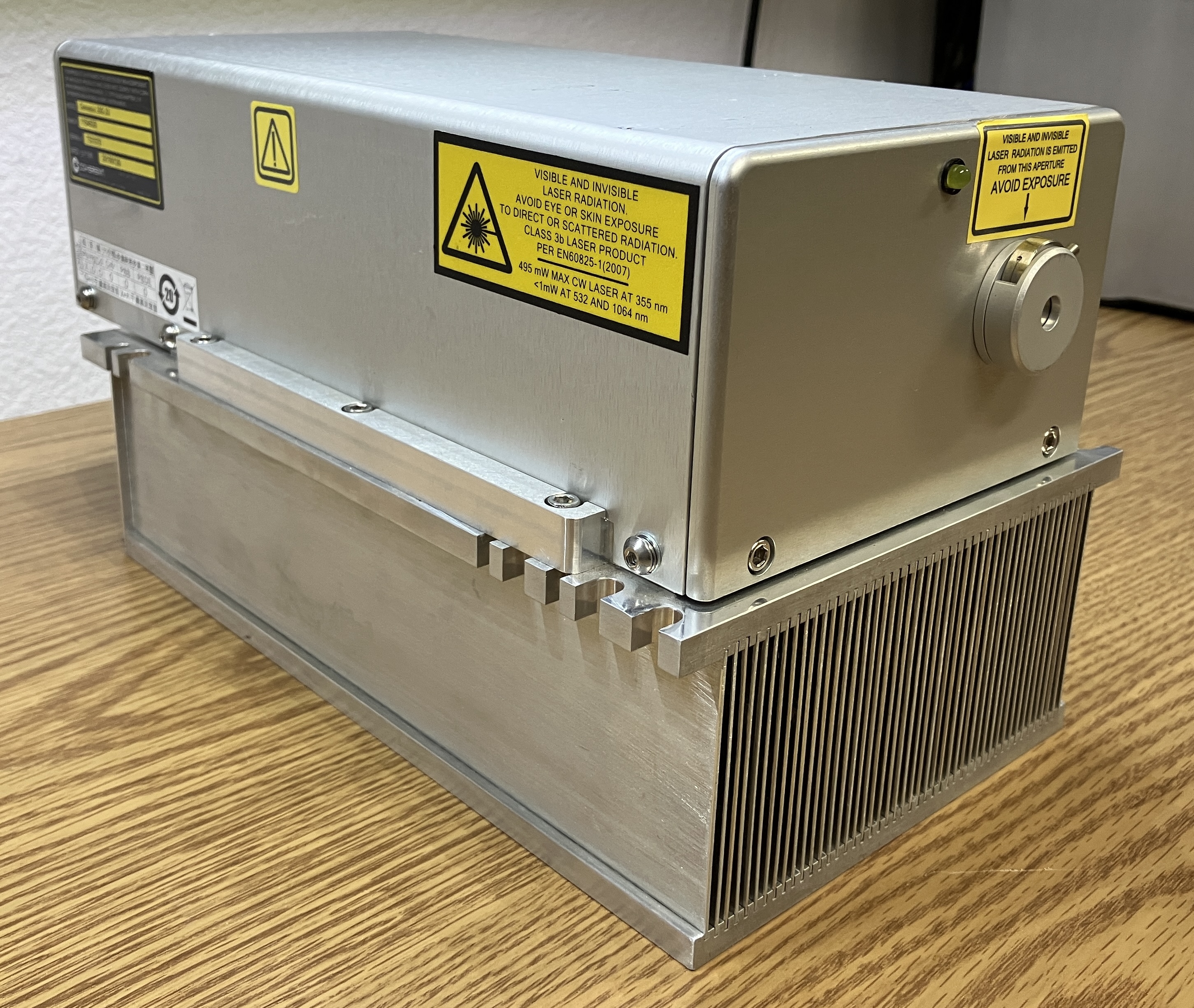
The laser head is secured to a large heatsink with very thick fins. The head and heatsink assembly weighs over 20lbs combined.
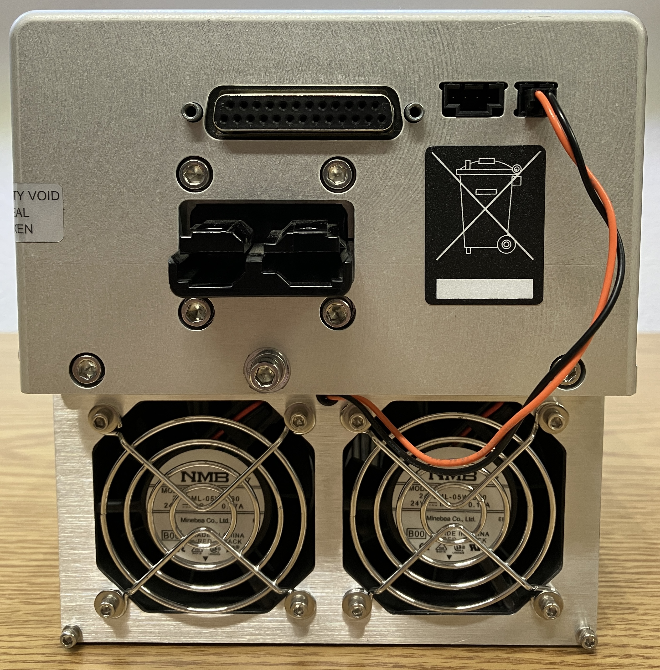
On the back of the laser head, there are several connections. The DB-25 connector is for head control, monitoring, and low current functions including the TEC. The large Anderson connector is for the high current pump diode. Two additional case ground wires run alongside the pump diode connections within the jacket of the high current wiring harness. The ground wires are secured to the laser head and power supply via spade lug connectors. The 4-pin connector is labeled "user interlock" on the circuit board and is not used in our application. The 2-pin connector is for the fans mounted below on the heatsink, which only ramp up as needed and even stop when active cooling is not required.
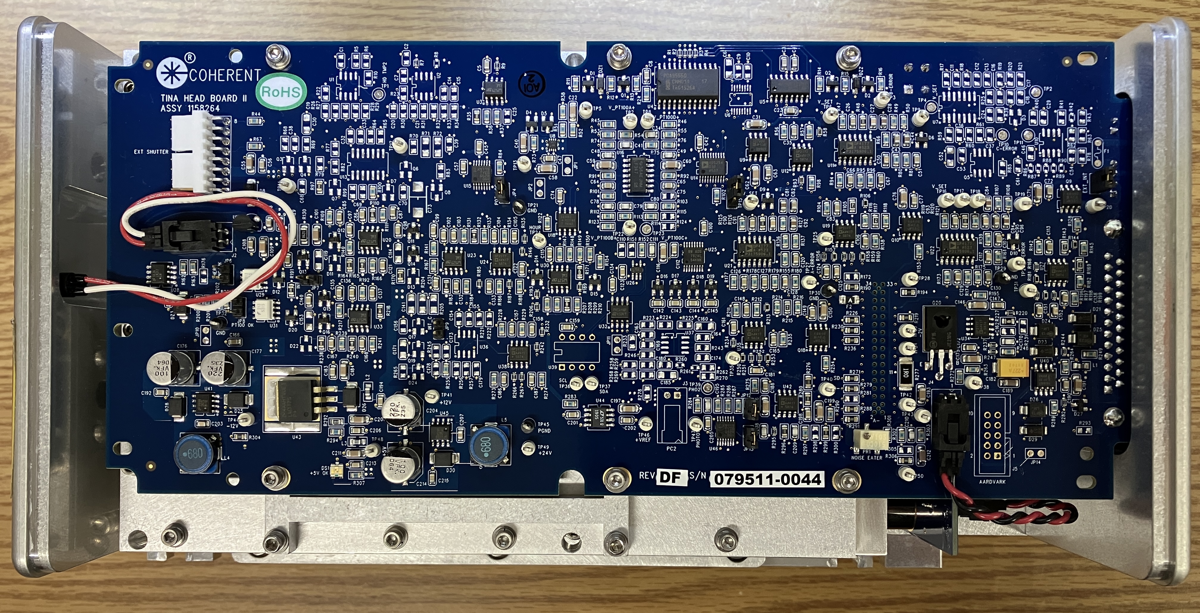
Removing the top cover of the laser head reveals a large circuit board that runs the entire length of the casing. This circuit board is labeled "TINA HEAD BOARD II" and is one of several variants that can be present in the Genesis lasers, depending on the model. The circuit board is secured to the optical cavity casing below by several screws and connects to the TEC, side board, and emission LED via individual connectors. The board connects to the internal components of the optical cavity via a dual row pin header connector, it simply presses on to the connector which is mounted to the back of the optical cavity enclosure. There is an external shutter connector on the board located near the emission indicator LED, but there is no electronic shutter on our unit, only the typical mechanical shutter. The TINA head board has many clearly-labeled test points which is appreciated, and quite uncommon to see on commercial laser systems. Most connectors are labeled as well. Interestingly, there is seemingly no primary MCU or processor on the head board, only the individual components needed for serial (I2C) communication and temperature regulation/monitoring of the optical components. There is only one potentiometer, labeled "NOISE EATER", on the TINA head board. We are not sure what purpose this served, but it is worth noting that the connector located next to the potentiometer is labeled "N_EATER". The harness from this connector runs down below to the circuit board mounted to the optical cavity, perpendicular to the head board. Since there is no primary MCU, and just one potentiometer, we assume that digital potentiometers are used for configuring the majority of the laser's operating parameters.
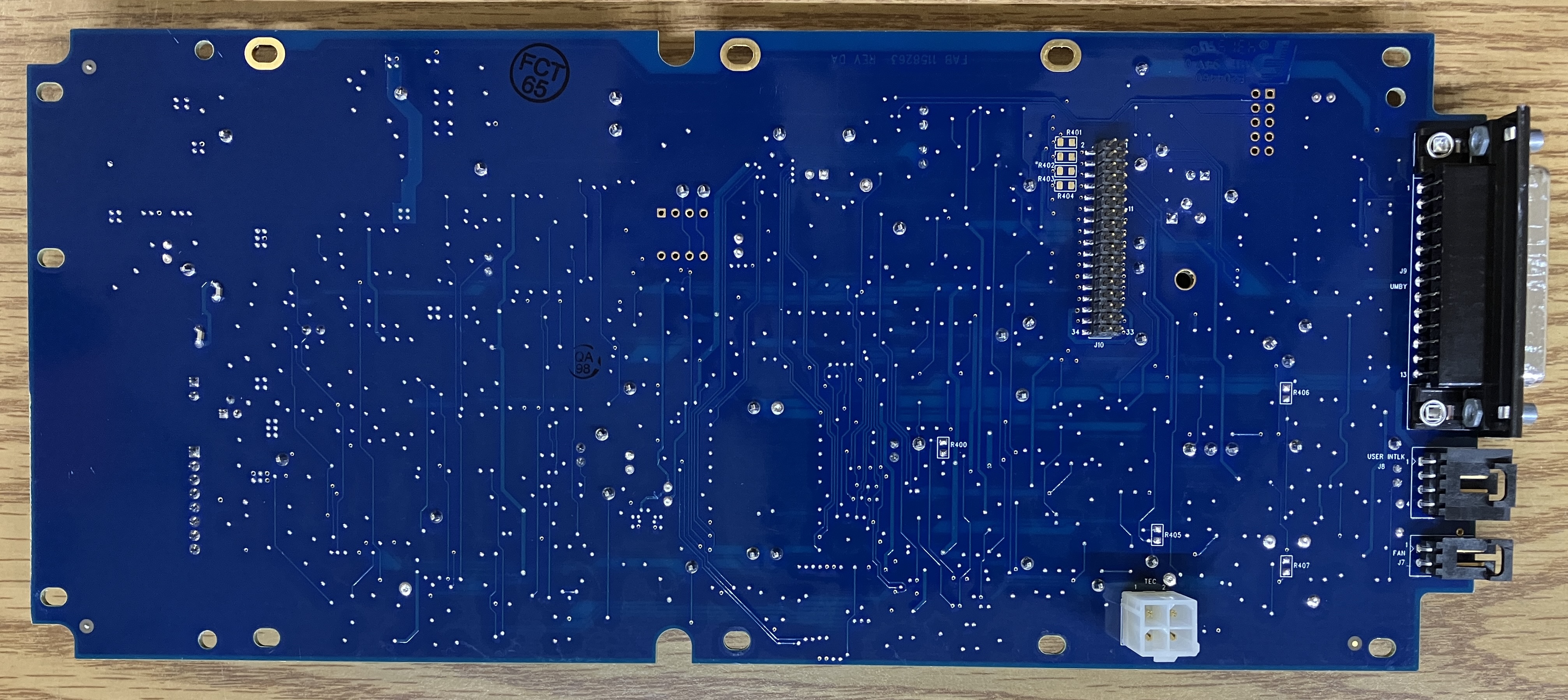
On the bottom of the TINA head board, the only notable components are the various connectors mentioned earlier. UMBY (umbilical) for connection to the power supply, fan, user interlock, TEC, and the dual row pin header connection for the optical cavity components.
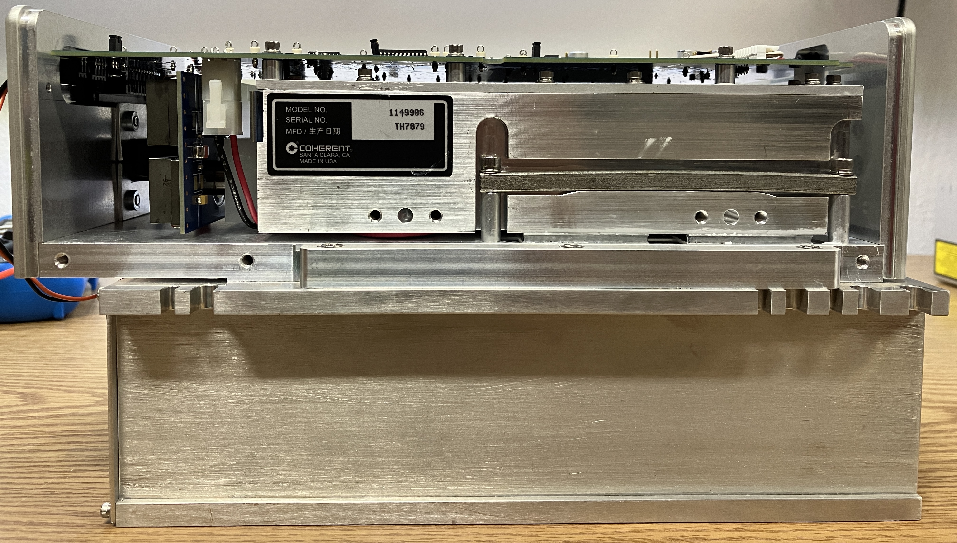
Here is a side view of the Genesis 355 laser head. The large resonant cavity is securely mounted to the head outer casing by torsion bars on either side. They clamp the cavity down onto two large TECs which make contact with the outer base plate of the laser head. The connector for the TECs is visible in the below image, it is on the reverse side of the large circuit board and faces downwards.
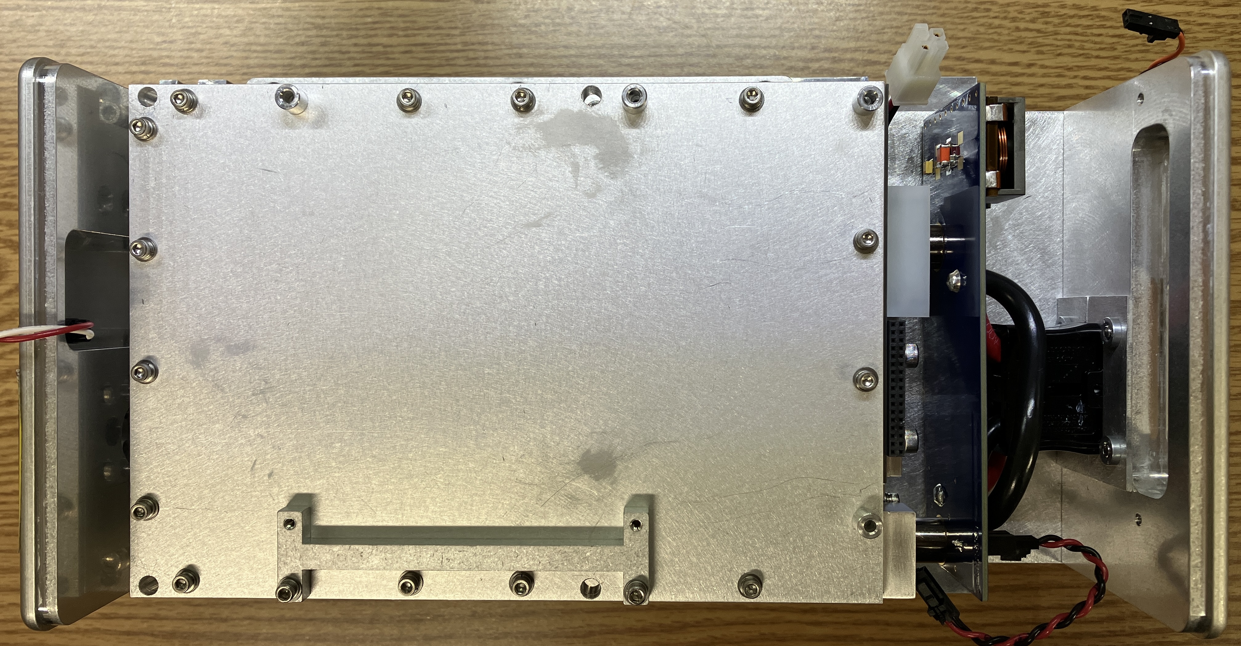
With the TINA head board removed, we can see the top cover of the sealed resonant cavity, secured by several screws. There is an additional circuit board mounted to the rear of the resonant cavity, directly behind the connectors on the laser head. This board serves as the interface between the TINA head board and the components within the resonant cavity. It also has two large EPCOS/TDK B82559 SMD chokes mounted to the interface board. The chokes minimize EMI (electromagnetic interference) and electrical noise to promote a higher level of stability for the pump diode. Beside the chokes are the two high current terminals which bridge the connection between the pump diode inside the cavity and the Andersen connector on the back of the laser head. There is one additional 2-wire connector that goes from the head control board N_EATER plug to this interface board. We are not fully certain of its function.
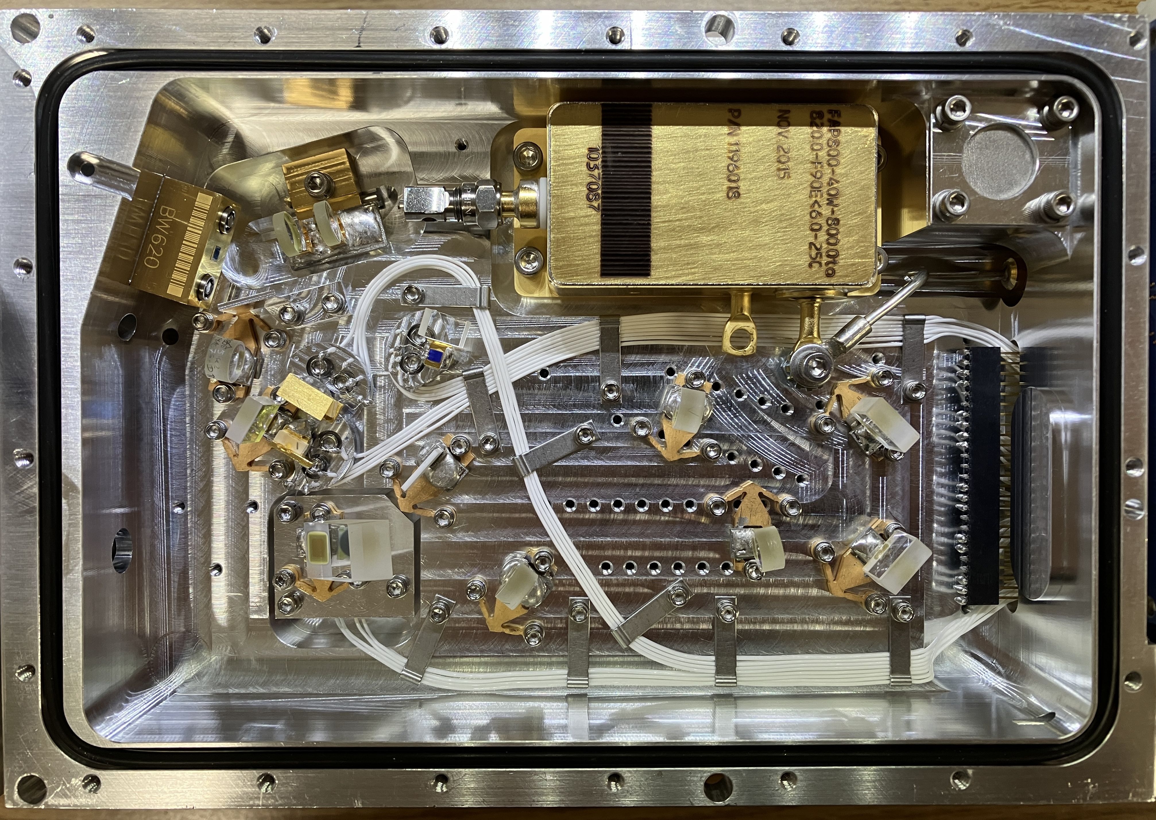
Below is an image of one of the most amazing, and complex, resonant cavities we have seen in a laser. We do not yet have a full understanding of the beam path. Here's what we do know: A 40-watt 808nm pump diode module is the source of laser light in this system. It is a Coherent FAP800-40W series pump diode bar, data sheet linked at the bottom of this page. Since this is an OPSL laser, an OPS chip is responsible for a portion of the light conversion process. We also believe that both SHG (second harmonic generation) and THG (third harmonic generation) are taking place in this resonant cavity. Due to the design of the circuit board being mounted directly on top of the resonant cavity, we cannot operate this laser system with the cover removed and a clear view of the resonant cavity. This is probably for the better, as a 40-watt pump diode being exposed is insanely dangerous! However, we would like to point out that based on the diode current measurement from the software, it is likely that this pump diode is being extremely under-driven. The software reports only slightly above 20 amps of diode current when producing the full 20mW of laser output. According to the data sheet, the FAP800 pump diode has an operating current of over 50 amps!
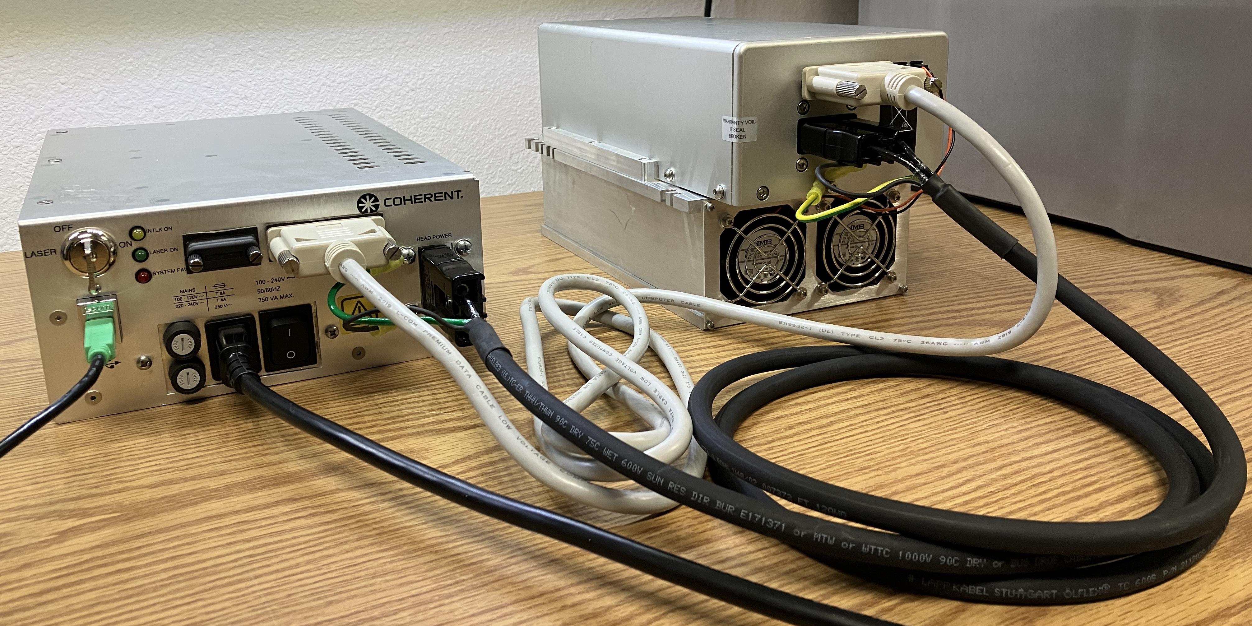
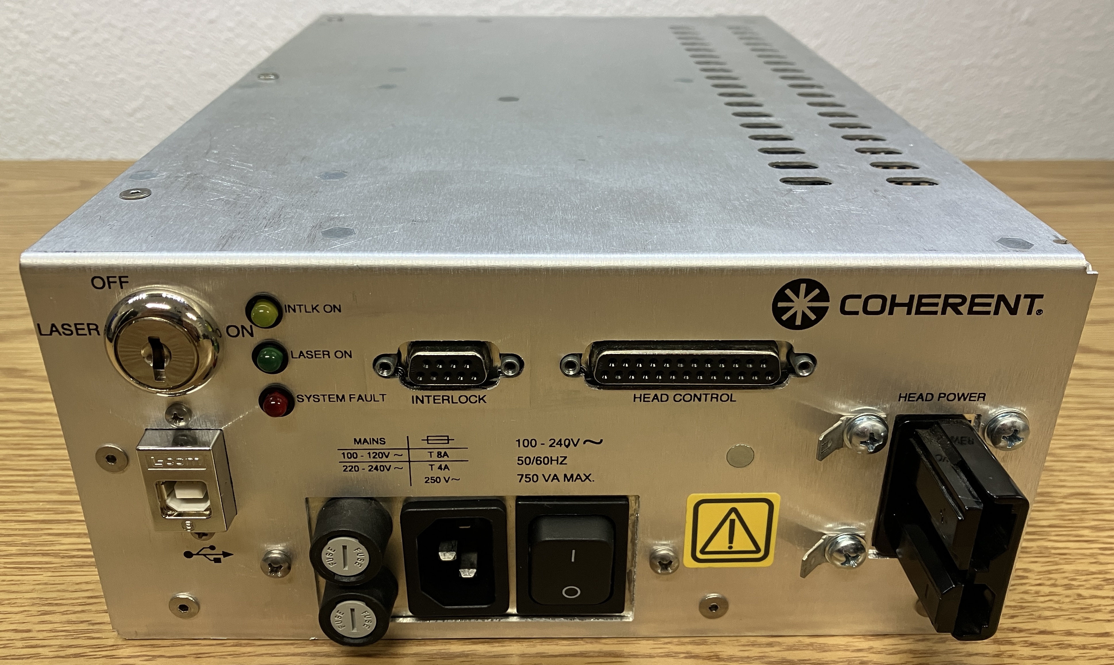
The driver system used with the Genesis laser heads is called the "HOPS power supply" from Coherent. There is a bench-top version for lab use, and an OEM version (pictured below) that was usually shipped with these laser systems. The HOPS power supply is capable of meeting the high current requirements of the laser head and also features a USB digital control interface. The power supply features the typical key-switch and indicator LEDs common on most laser power supplies, along with an AC input module (IEC connector, fuses, power switch). Connections on the power supply include the Anderson connector and grounding lugs for the high-current wiring harness for the laser head. The DB-25 connector is used for head control and monitoring. The DB-9 connector is for the interlock, and is usually bridged by a bypass plug. TO SATISFY THE INTERLOCK AT THE DB-9 CONNECTOR, BRIDGE PIN 1 TO 2 AND BRIDGE PIN 6 TO 7. The USB-B port is for monitoring and controlling the laser system via a computer running the compatible software.
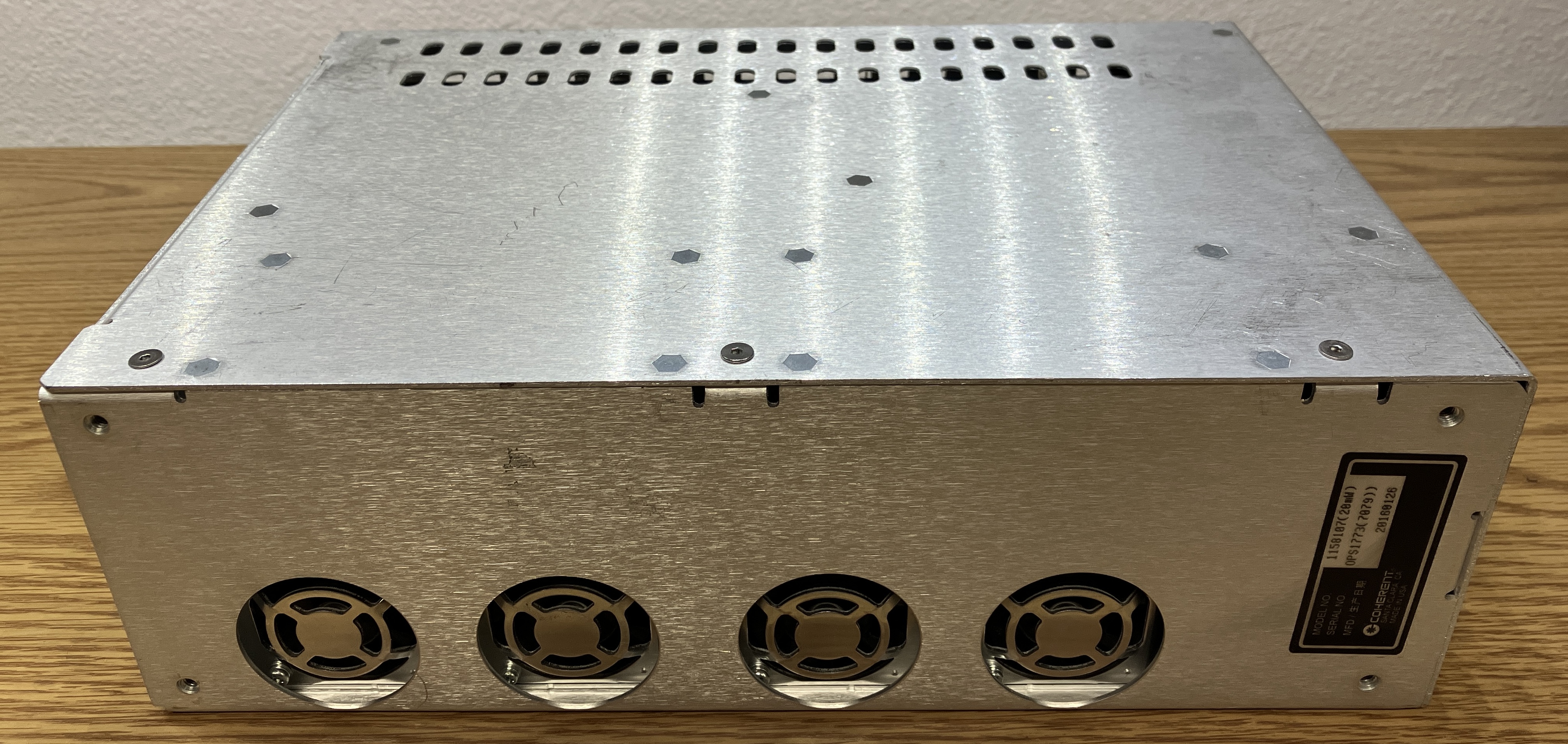
The HOPS power supply (OEM version) is just a plain aluminum enclosure with plenty of ventilation slots and cut-outs for the fans. The power supply is designed purely for function, and is not even painted or anodized.
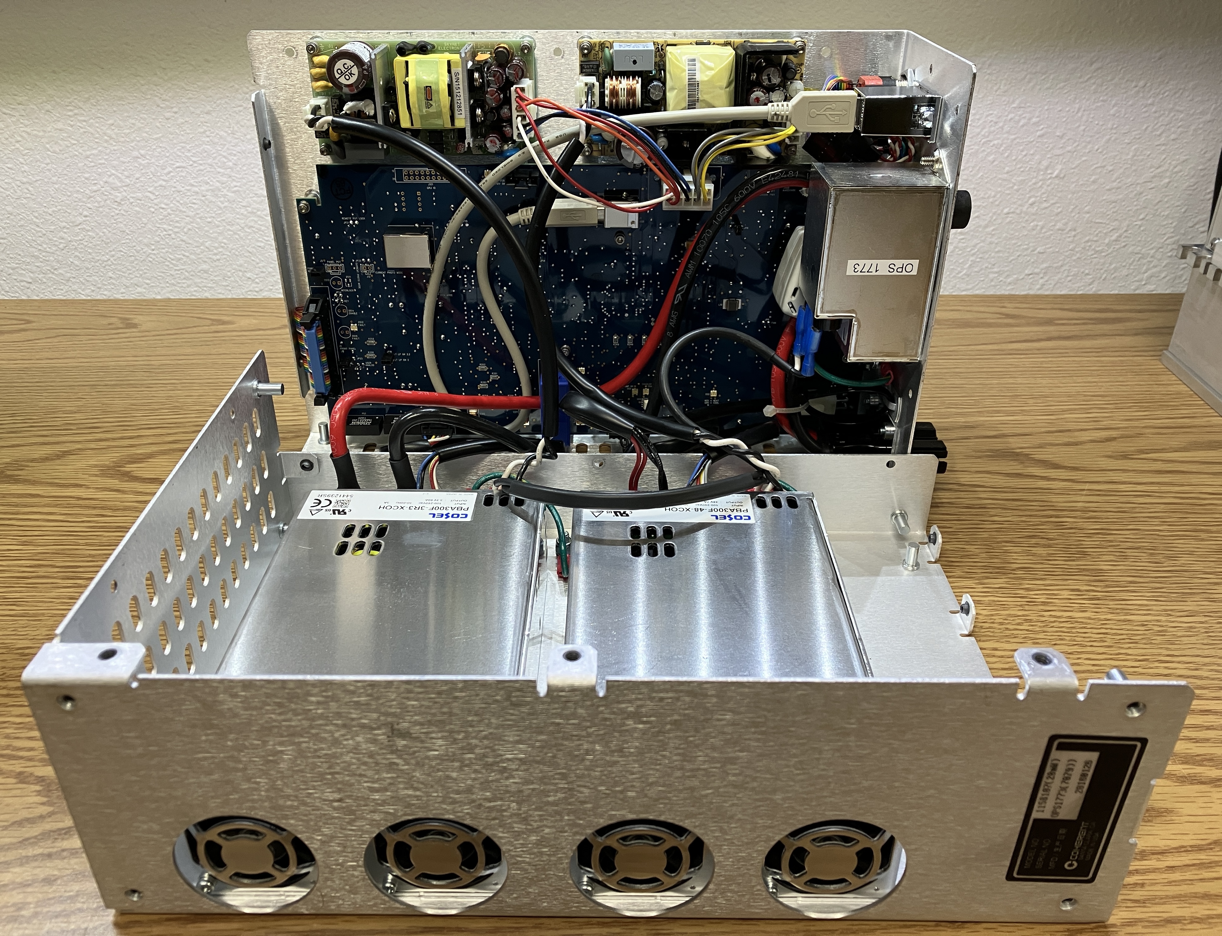
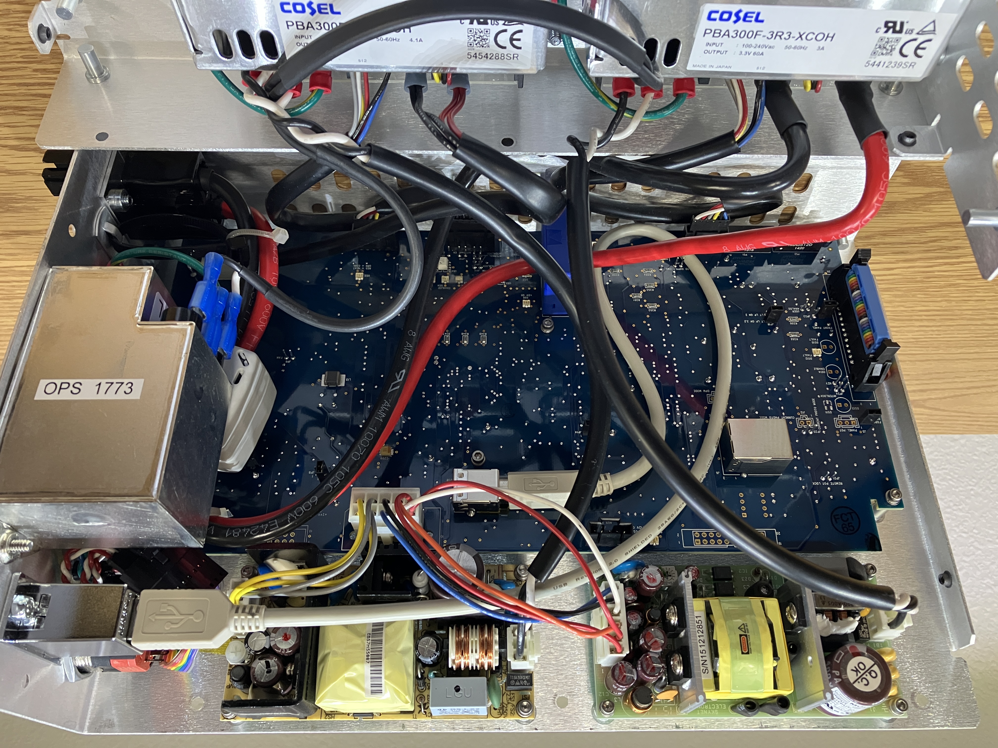
Removing several screws will allow the power supply casing to separate into two sections. It's a pretty serviceable unit, but disconnecting the wiring between the two sections really helps make the process easier. Luckily, all connections are easy-to-remove plugs or screw terminals. The two COSEL AC-DC converters are doing the majority of the work in this system. Pictured below, the unit on the left is a COSEL PBA300F-3R3-XCOH (3.3VDC 60A output) and is responsible for providing high current, low voltage power to the pump diode. The unit on the right is a COSEL PBA300F-48-XCOH (48VDC 7A) and is responsible for providing power to the TECs contained within the laser head. These AC-DC converters are controlled by the motherboard mounted to the other half of the HOPS power supply enclosure. The output of the first AC-DC converter goes directly to the Andersen connector on the front panel of the HOPS power supply enclosure, and leads directly to the pump diode. There does not seem to be any additional current control or regulation between the COSEL unit and the pump diode. Each AC-DC converter has a 6-pin wiring harness for control and monitoring that connects to a plug on the motherboard, labeled "LDD DRIVER" and "TEC DRIVER", respectively.
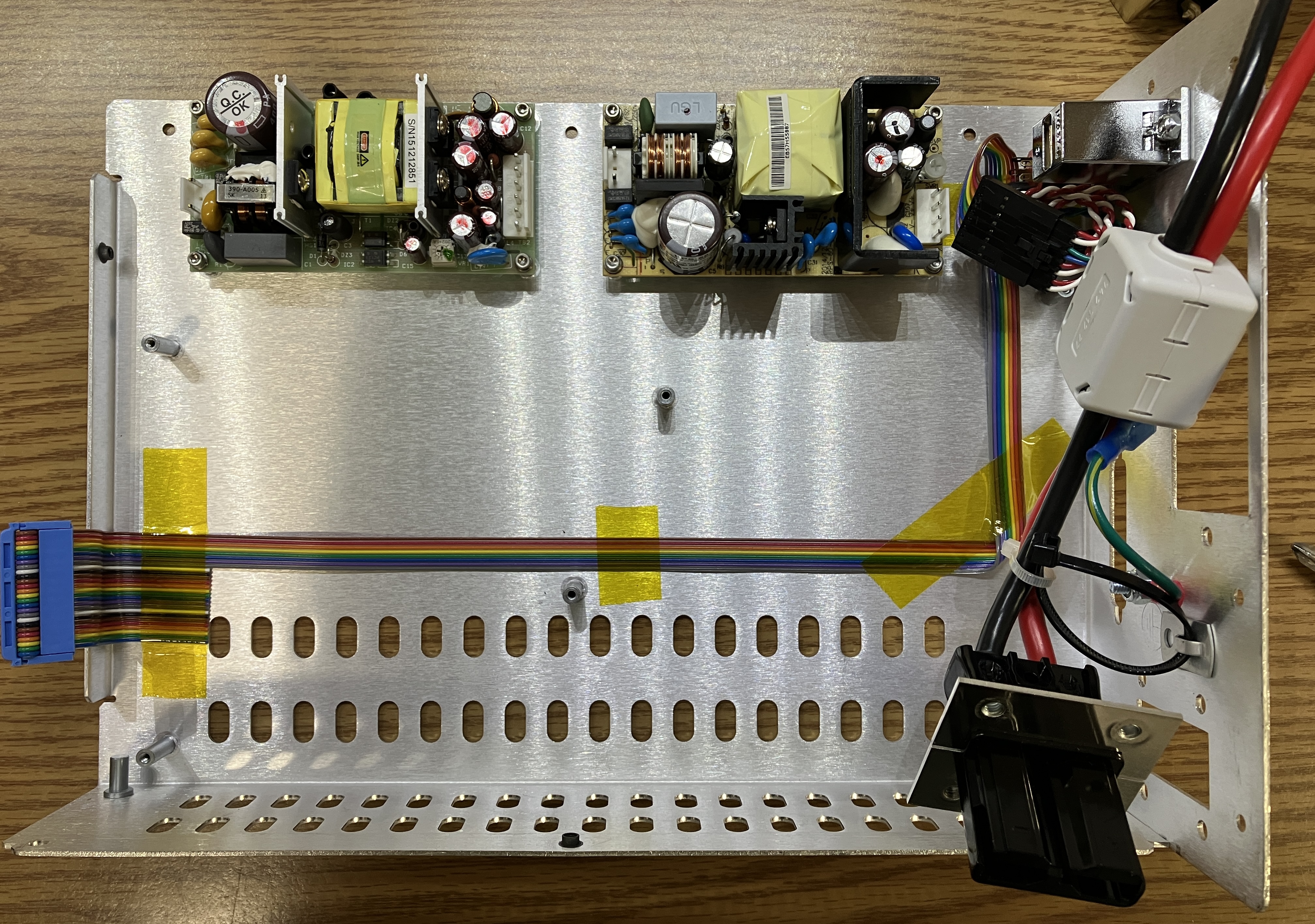
On the top section of the HOPS power supply, there are two additional, but smaller, AC-DC converter modules. The unit on the left is a Skynet Electronics (great name!) SNP-Y041 which converts AC into 3 different DC rails: 5V, 12V, and -12V. The AC-DC converter module on the right is a more generic unit and does not have any clear identification markings. The output of both the AC-DC converter modules lead to a connector on the HOPS main motherboard labeled "HOUSE KEEPER PWR". Therefore, it seems that these smaller AC-DC converter modules are responsible for providing power for the control and logic of the laser system. There is an internal USB-B connector on the motherboard and a short USB-A to USB-B cable that connects to an L-COM panel mount USB connector on the front of the power supply. The mains filtering module is mounted to the front of the case and includes the AC input plug, power switch, and some fuses. The key switch and indicator LEDs are connected to the motherboard via a multi-colored ribbon cable.
With the motherboard and mains filtering module removed, we can see the ribbon cable and Anderson connector. Only a few of the connections on the ribbon cable seem to be in use, with the rest having been cut off shortly after the connector. From our research and markings on the board, we learned that different versions of this power supply can include manual current/output power controls. This could explain the unused section of the ribbon cable.
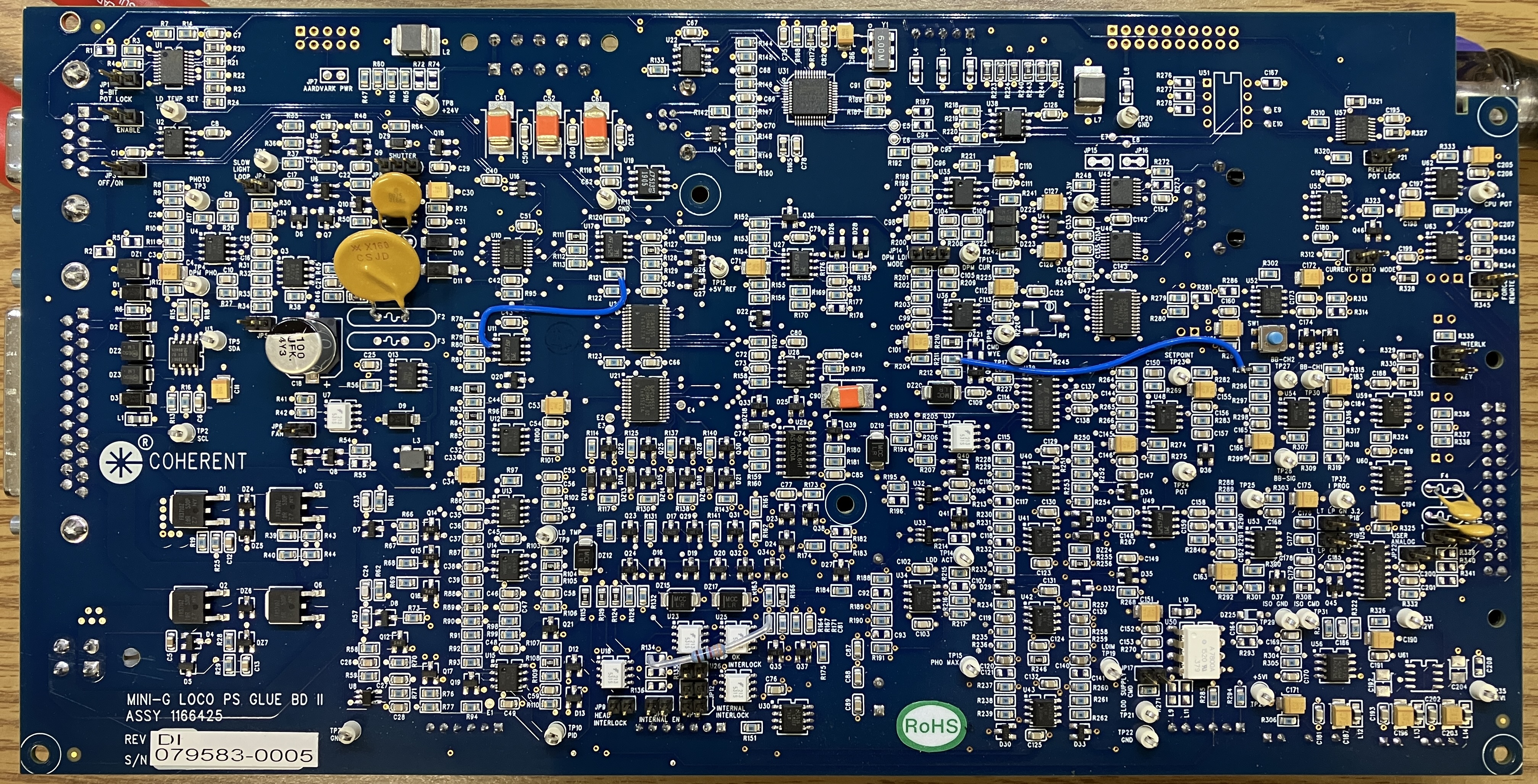
The HOPS power supply motherboard is called the "HOPS MINI-G LOCO PS GLUE BD II" by Coherent, according to the silk screen. As evident by the name, it really is more of a glue or control board than a complex motherboard with a processor. Don't get us wrong, it's still quite complicated, but the most puzzling aspect of this motherboard is the complete lack of an MCU or processor. It has plenty of digital interfaces including serial and USB, but no central processor. It appears that the individual functions are all being handled by separate sections of circuitry. Based on examination of the board, we know that multiple I2C and RS-232 serial interfaces are used for communication throughout the board. There are many clearly-labeled test points on the top of the board, which is appreciated. Also, most of the connectors are clearly labeled as well. Troubleshooting and repairing a HOPS power supply would likely not be as daunting as it looks, due to the lack of a software-controlled processor and the clear labeling. As mentioned with the head control board, we suspect that digital potentiometers are in use since there are no traditional potentiometers on the HOPS power supply motherboard and only one on the head circuit board. Notable test points include LD TEMP SET, SETPOINT, DPM CUR, PROG, PHO MAX, SDA, and SDL. The last two indicate a serial interface being present. There are many jumpers on the board as well, which include: POT LOCK, FORCE REMOTE, USER ANALOG, CURRENT PHOTO MODE, KEY, INTERLOCK, and more.
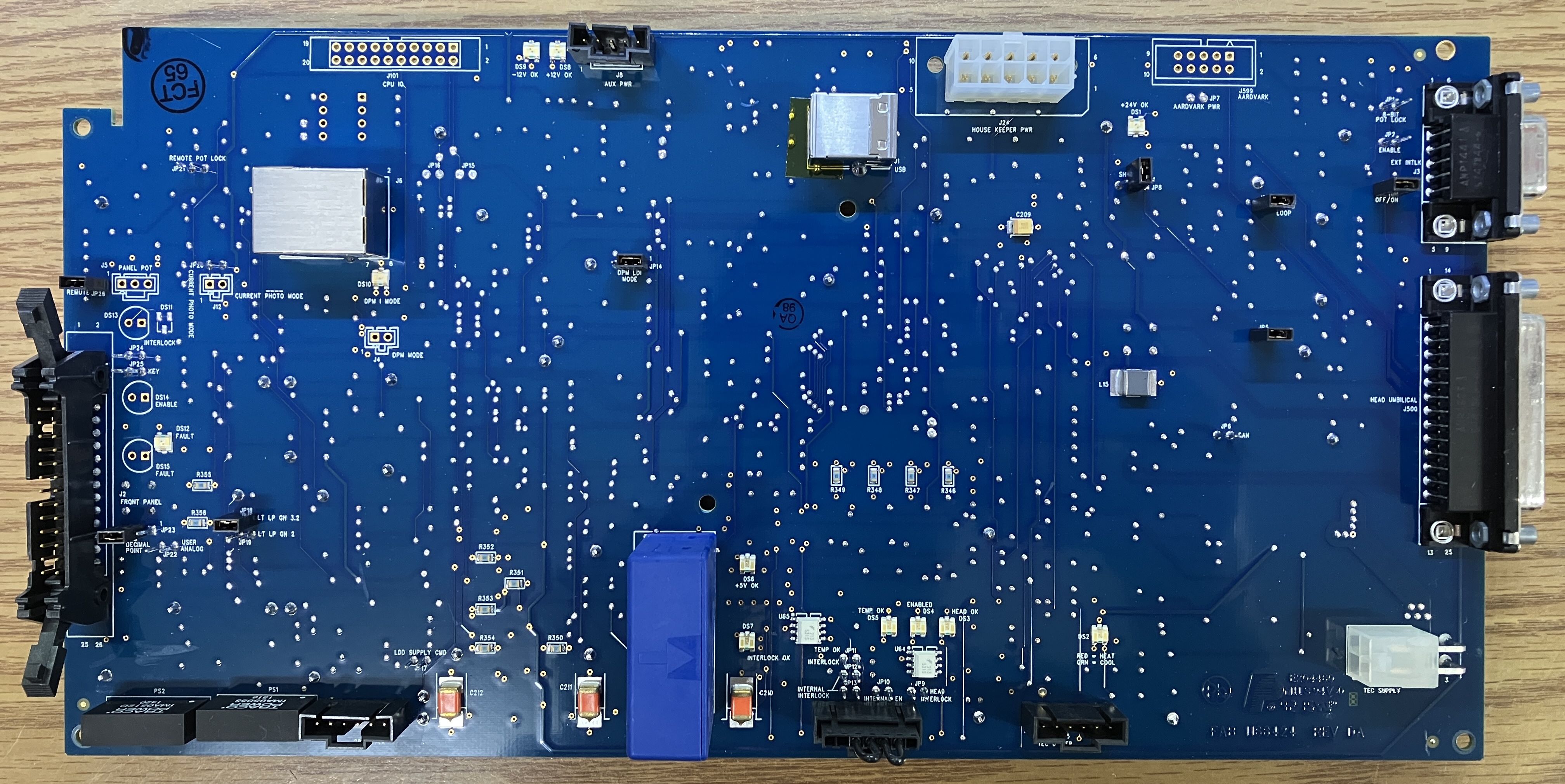
On the other side of the HOPS power supply motherboard, there are several connectors and jumpers. They are clearly labeled and include the front panel connector, house keeper power, interlock, TEC supply, LDD driver, and TEC driver. All of these connectors route to components within the HOPS power supply. The DB-25 and DB-9 connectors are mounted directly on the motherboard and are exposed out through the front of the casing. Additionally, there are several indicator LEDs that display the status of the power supply and laser system. They are labeled as well. Many of the jumpers continue through to the other side of the board and can be accessed on either side. There is an unpopulated connector outline on the board labeled "CPU IO", we are not sure what this connector is for, but assume it has something to do with a missing primary CPU or MCU. There is a large current sense transformer mounted to the board, the positive laser diode connection passes through this transformer for monitoring. The side-mounted RJ-45 connector is an area where we focused significant effort. It's a serial interface that connects to two different channels. This serial interface is dissected further in the next section. A notable, but unpopulated connector, is the AARDVARK connector. We're not going to even speculate what this connector may be used for...
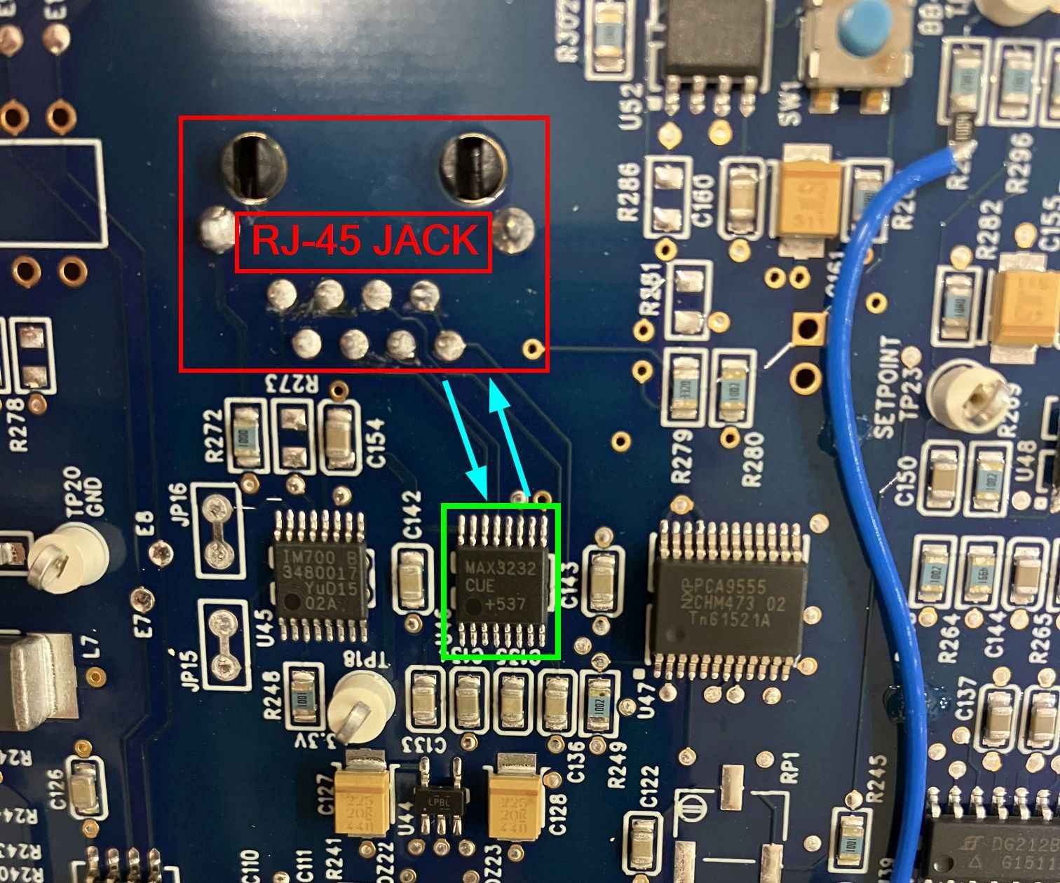
The RJ-45 jack (mounted on reverse side in the image below) is connected directly to a MAX3232CUE+ RS-232 transceiver. This transceiver has two independent serial channels, both of which are capable of receiving and transmitting data. The transceiver is able to convert between TTL/CMOS and RS-232 serial signals and is used to interface externally in this system via the RJ-45 connector. We spent a significant amount of time probing and analyzing the serial channels on this connector, but did not have any luck. This interface may be not implemented in this laser system, or perhaps it needs to be enabled via some sort diagnostic or programming procedure. This connector, along with the array of test points on the HOPS power supply motherboard, make this laser system an ideal candidate for further analysis. As we continue to work with this laser system, we will update this page accordingly with any new information.
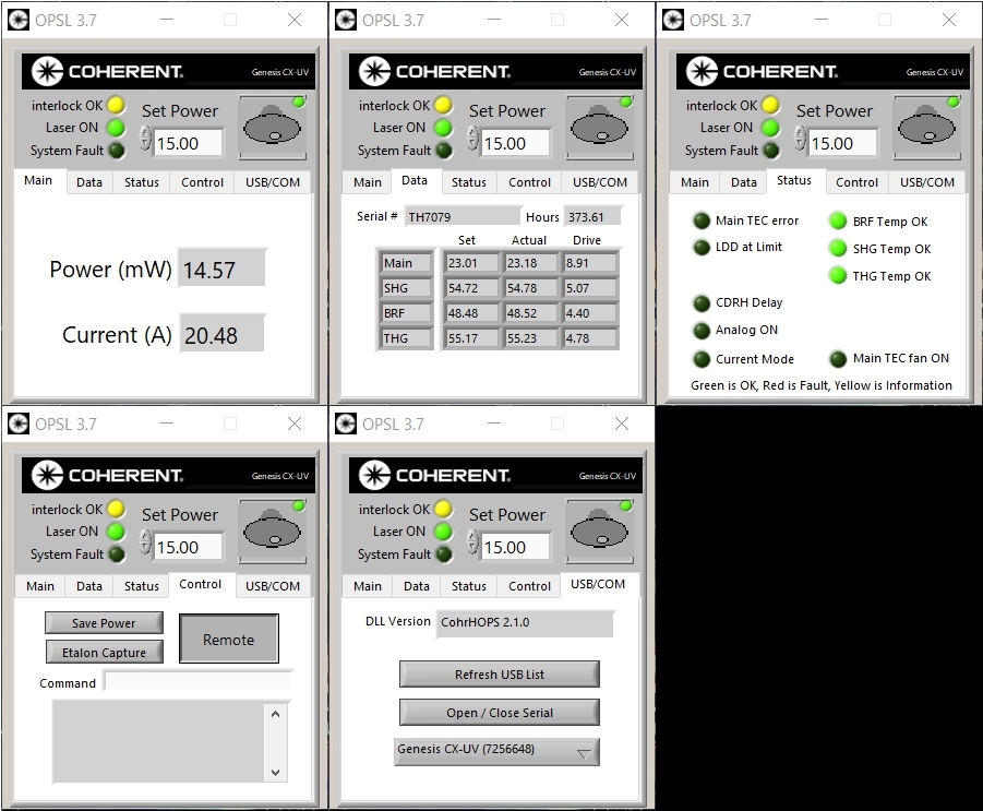
The GUI software developed by Coherent for the Genesis laser systems is called OPSL-GUI and can be downloaded freely from the Coherent website. The OPSL-GUI software is pretty simple and allows for monitoring and limited control over the laser system. The software provides quick access to information such as output power, diode current, and temperatures of the base plate as well as the optical components (BRF, SHG, THG). Laser output can be enabled/disabled by clicking on the key switch icon, and the output power can be adjusted. The startup output power can be saved to memory on the laser system and will persist even when power is removed. The Etalon Capture feature, when invoked, briefly reduces the diode power to zero and then immediately restores it back to the set value. The intention behind this function is to reset the lasing line position, which can drift over time as the cavity temperature fluctuates, which causes a reduction in overall output power. Additionally, if the laser system is operating in output power control mode, the pump diode current may be increased up to its limit as the system attempts to achieve the desired output power. Performing the Etalon Capture can help minimize this effect and reduce unneeded strain on the pump diode. The reason why the Etalon Capture is more effective than simply cycling the power or key switch as it prevents a significant shift in temperature of the optical components. Using they key or power switch would result in a delay before lasing is restarted, which would allow for temperature change, reducing the effectiveness of the procedure. When the OPSL-GUI software is installed, a link to a PDF will be included in the program's installation directory. This PDF contains valuable information about the DLL used for communication with the Genesis laser systems over the USB interface. Since many of the Genesis HOPS power supplies use an actual USB communication interface instead of a simple USB-to-serial converter (or an actual serial port), this DLL and PDF instructions are useful when trying to implement 3rd party software for laser communication. We plan to eventually integrate this DLL with our laser control software to enable compatibility with Genesis laser systems.
It's worth noting that we originally had some difficulty getting the OPSL-GUI software to communicate with the laser system. We installed the FTDI serial drivers (link below) and restarted the computer, this seemed to resolve the issue and communication with the laser system over USB has not been an issue since.