Directed Energy Systems is proud to present the FENRIR 24-B as the latest iteration of our laser show projector! It's capable of astonishingly bright and vibrant laser output, combined with the reliability and quality required by the most demanding entertainment environments! Many aspects of the show projector have been improved upon since the previous version (FENRIR 23-A). This write up will cover detailed specifications and features of the laser projector. If you are interested in learning more about the build process, check out the writeup for the FENRIR 23-A as both systems follow a similar build process and design philosophy. Below are some quick specifications for reference:
- Full color RGB (3 total laser diodes)
- Around 1400 mW of total output power (combined red, green, blue)
- Analog modulation of diode drivers
- 30,000 points-per-second scanners
- Standard ILDA input, no built-in show card
- Active cooling by case fan, thermal monitoring
- External interlock connection, key-switch, emission indicators
- Dedicated controller for monitoring and interlocks
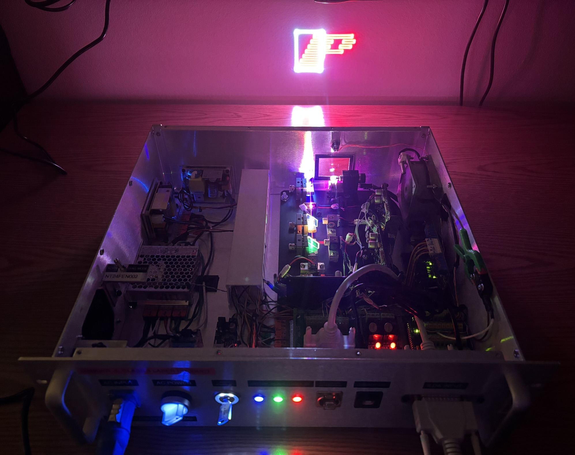
In the image below, the top cover has been removed and the projector is displaying a logo that may be familiar to some! We use Pangolin DAC hardware and laser show design software with our projectors. It's not cheap, but it's the best in the industry.
The FENRIR 24-B enclosure is a 3U aluminum rack-mount case, very similar to the previous FENRIR, just a bit smaller. All openings for switches and components were either made using a drill or cut using a Dremel tool. The top cover is secured in place by several screws on the top and sides.
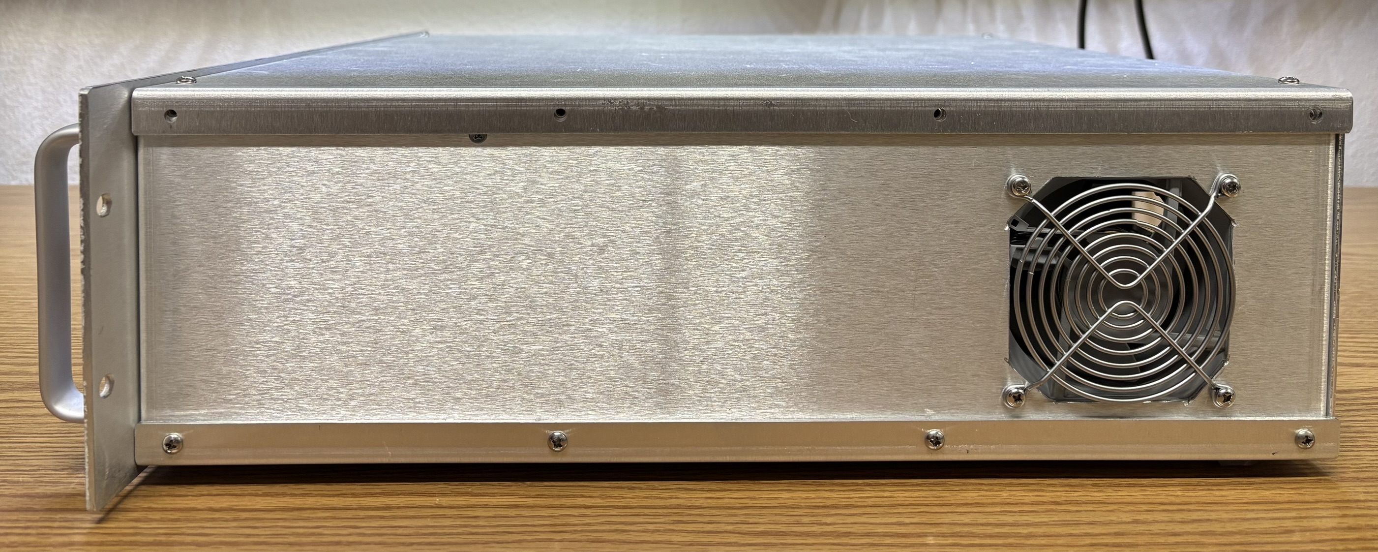
On the side of the casing is the filtered air intake. A removable cover allows the filter to be easily cleaned or changed.
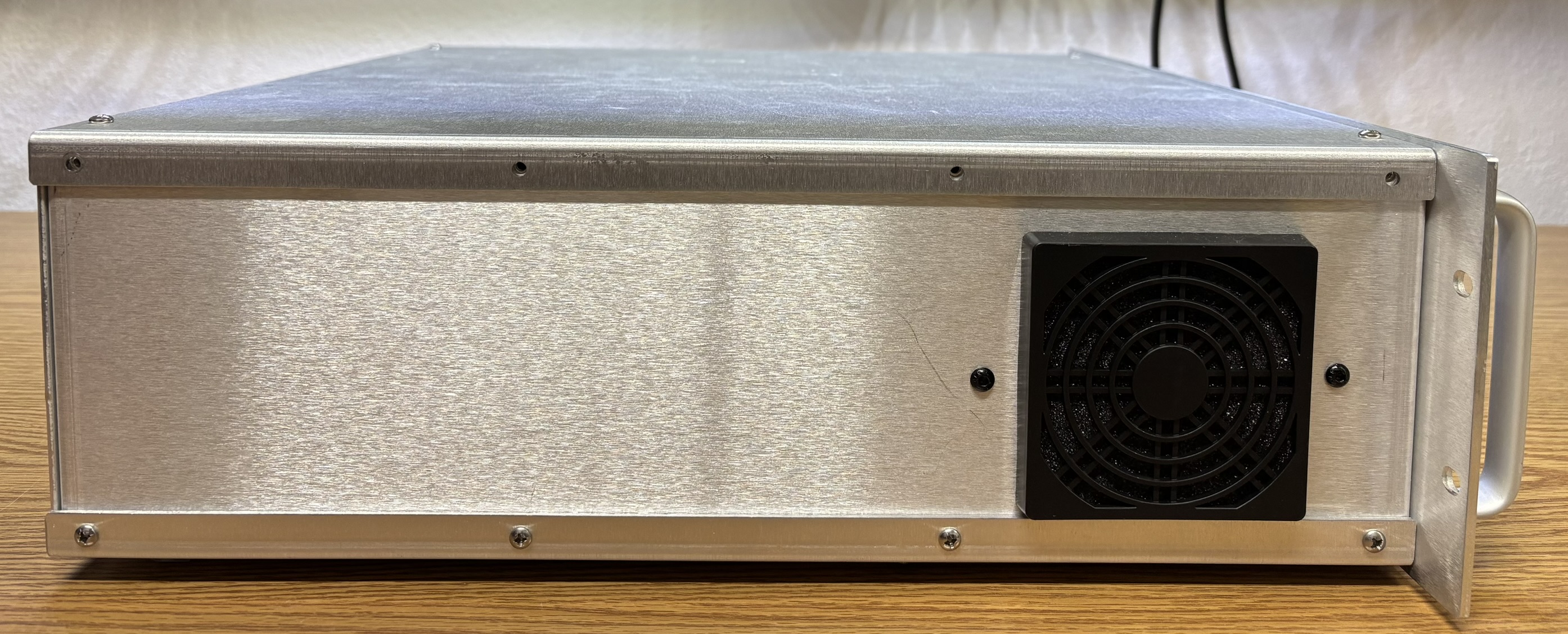
On the other side is the cooling fan that exhausts air after is passes through the internal components.
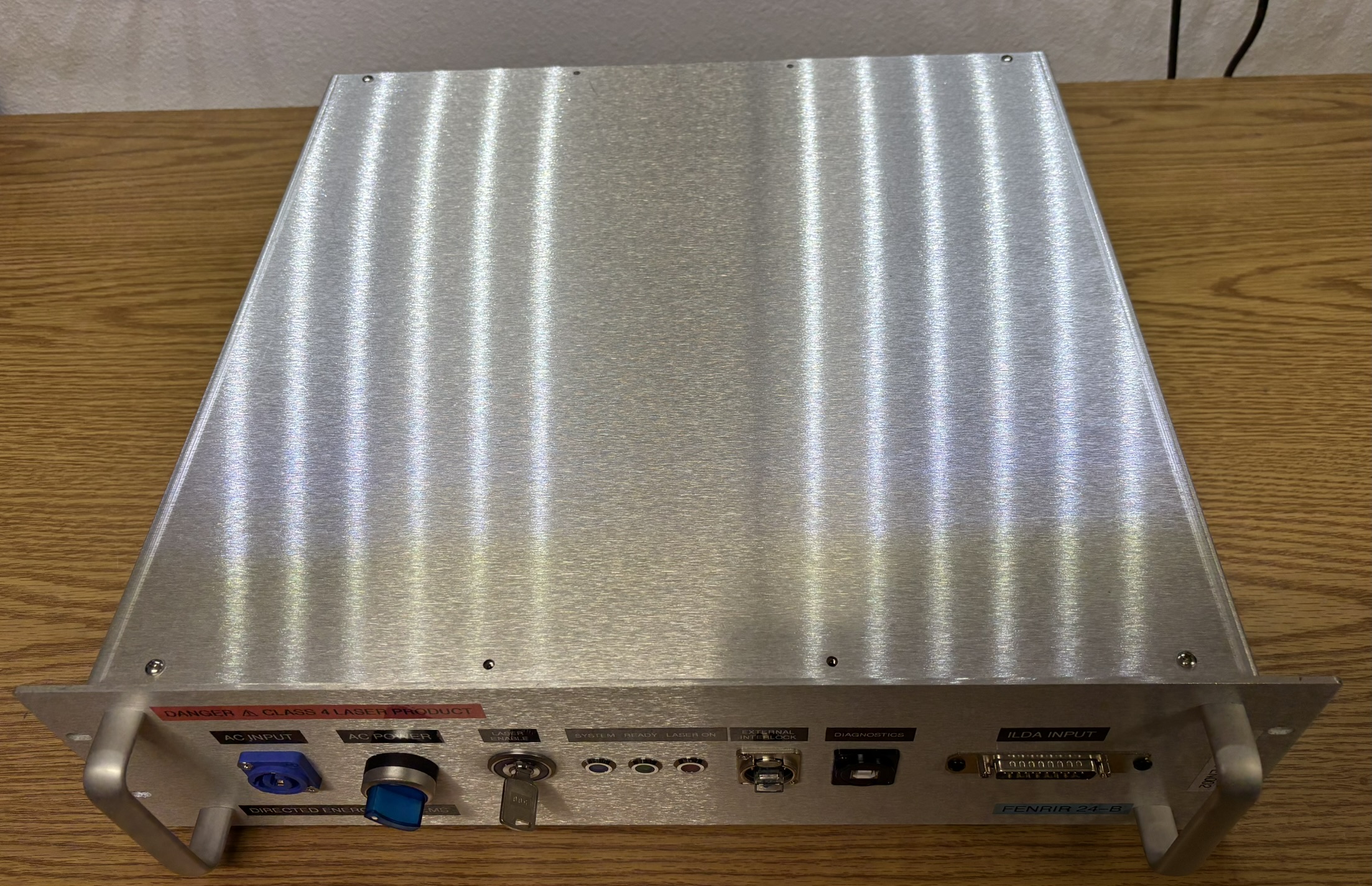
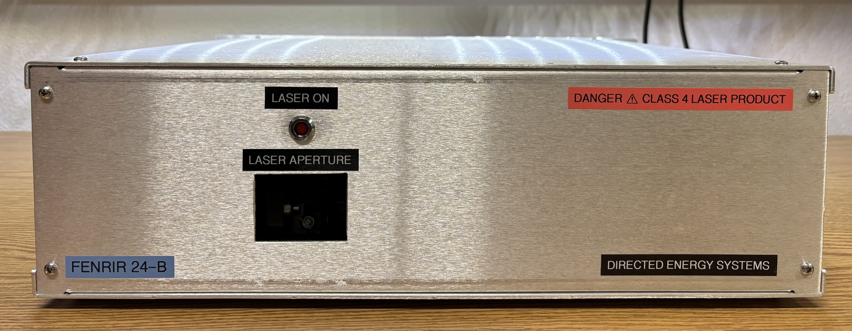
On the front of the unit is an emission indicator LED, glass-covered laser output aperture, and some warning and information labels.
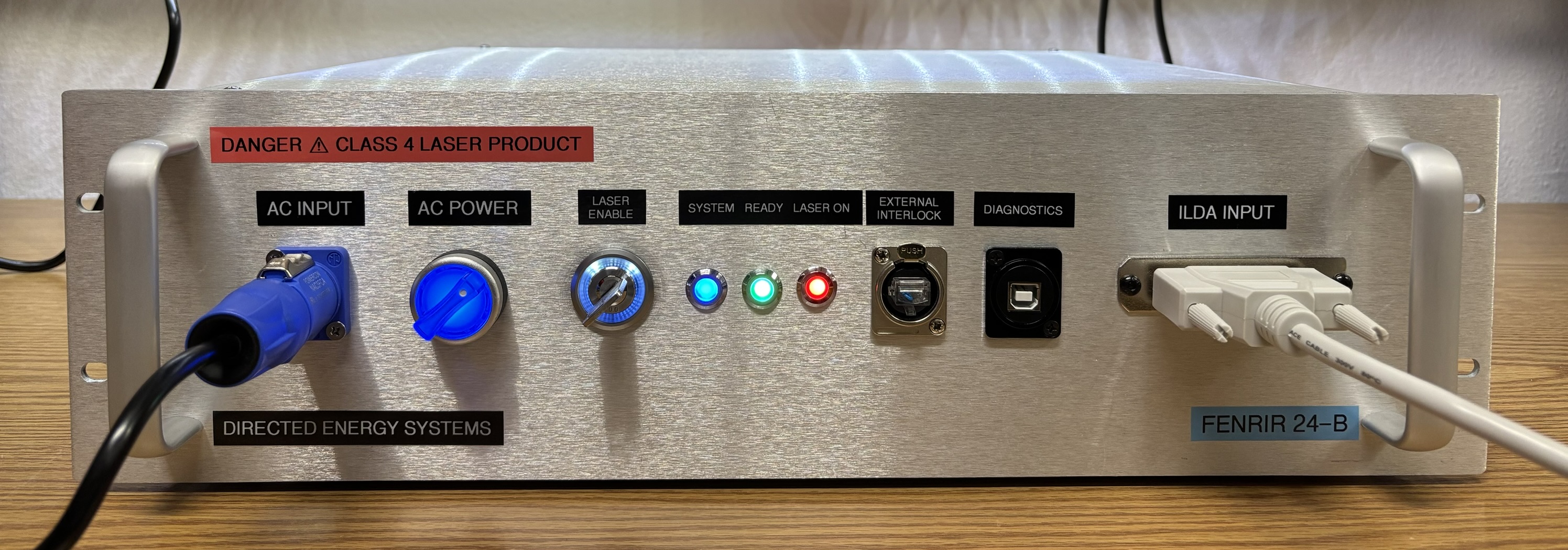
The control panel features a very similar design to the FENRIR 23-A. The layout was condensed and cleaned up slightly. The AC input is a Neutrik PowerCON twist-lock connector. The blue illuminated rotary switch enables AC power when switched on. The interlock key-switch is from the LW Silhouette series manufactured by IDEC. It's an expensive key-switch, but is of exceptional quality and features a neat illuminated ring. The SYSTEM LED indicates that the internal controller is operational. The READY LED flashes during the CDRH delay and will remain steady when all interlocks are closed and the delay has completed. The LASER ON LED illuminates steady when the system is capable of emitting. The interlock connector is a panel mount RJ-45 EtherCON connector. A jumper is installed to bypass the interlock in the picture below. The diagnostics USB connector is for flashing the controller's firmware and monitoring system status and operating parameters. Lastly, the ILDA connection was constructed from a modified PCI parallel port bracket.
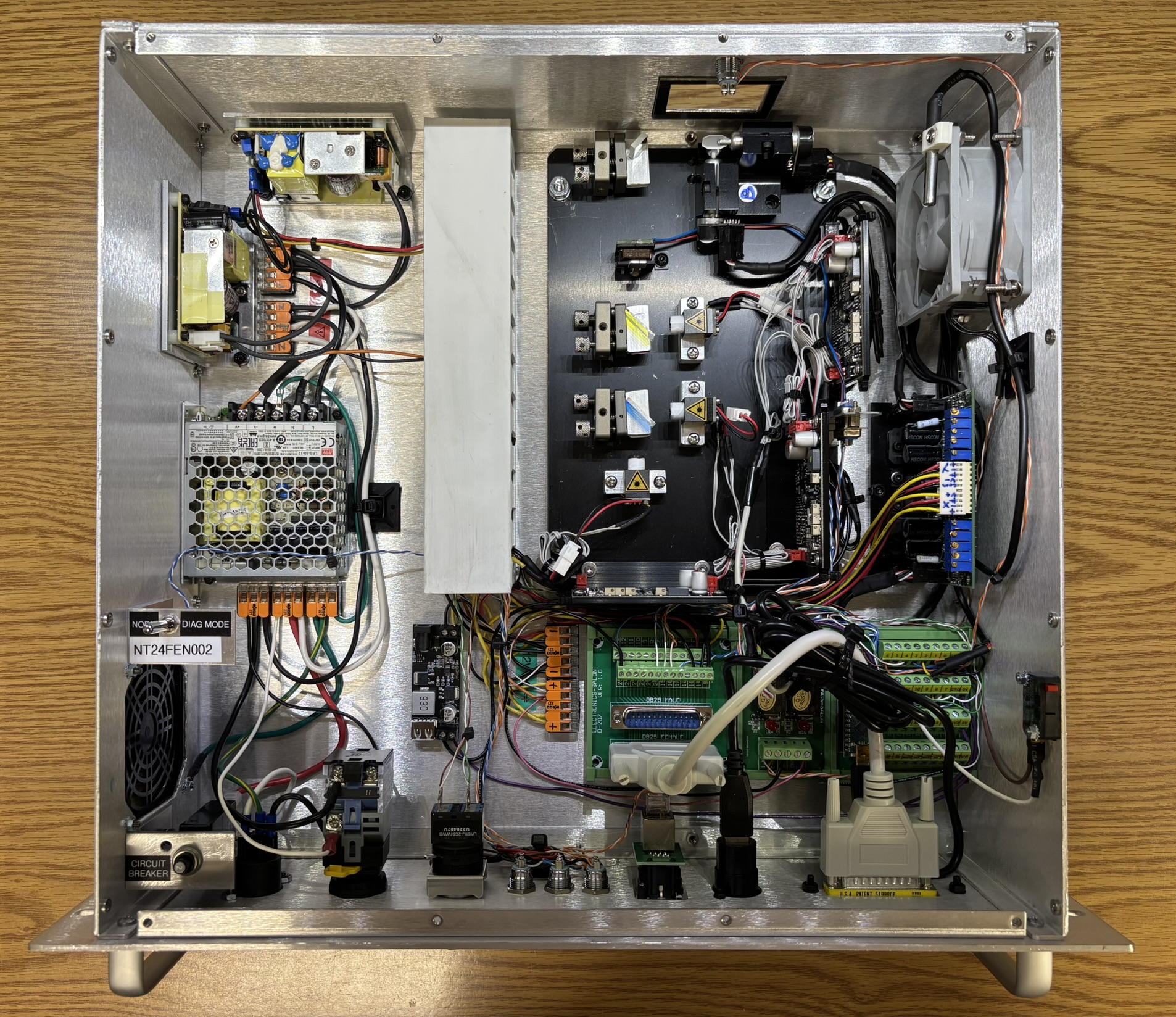
With the top cover removed, the internal components of the system are visible. We put more thought into component placement and layout to better manage the cabling and clean up the inside. There is still more work to be done in future revisions. To better explain the details, we will break down the internal components into the following sections below: power supply, optical, and control.
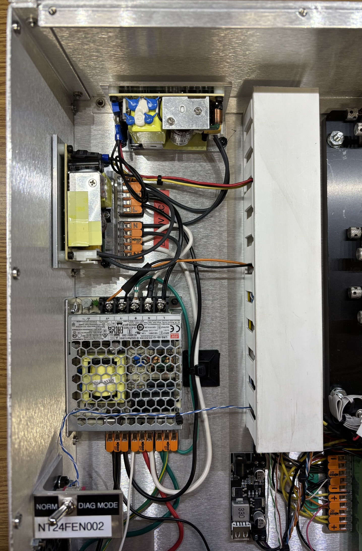
This is the power supply section. After passing through the PowerCON connector and rotary switch, AC power enters several WAGO connectors to be distributed to the individual power supplies. 12V DC power is supplied by a Mean Well LRS-50-12. 12V power is used for some of the control electronics and the fan. DC power is further stepped down to 5V by a DROK buck converter module (black PCB in lower right corner). 5V DC power is used for some of the indicators and the internal controller (Arduino Nano). There are two identical Mean Well RPS-65-24 power supplies that generate the +24V DC and -24V DC rails for the scanners. Since they are not split-rail power supplies, they are connected in a special floating output, common ground configuration. Excess wiring is contained within the white plastic cable management duct.
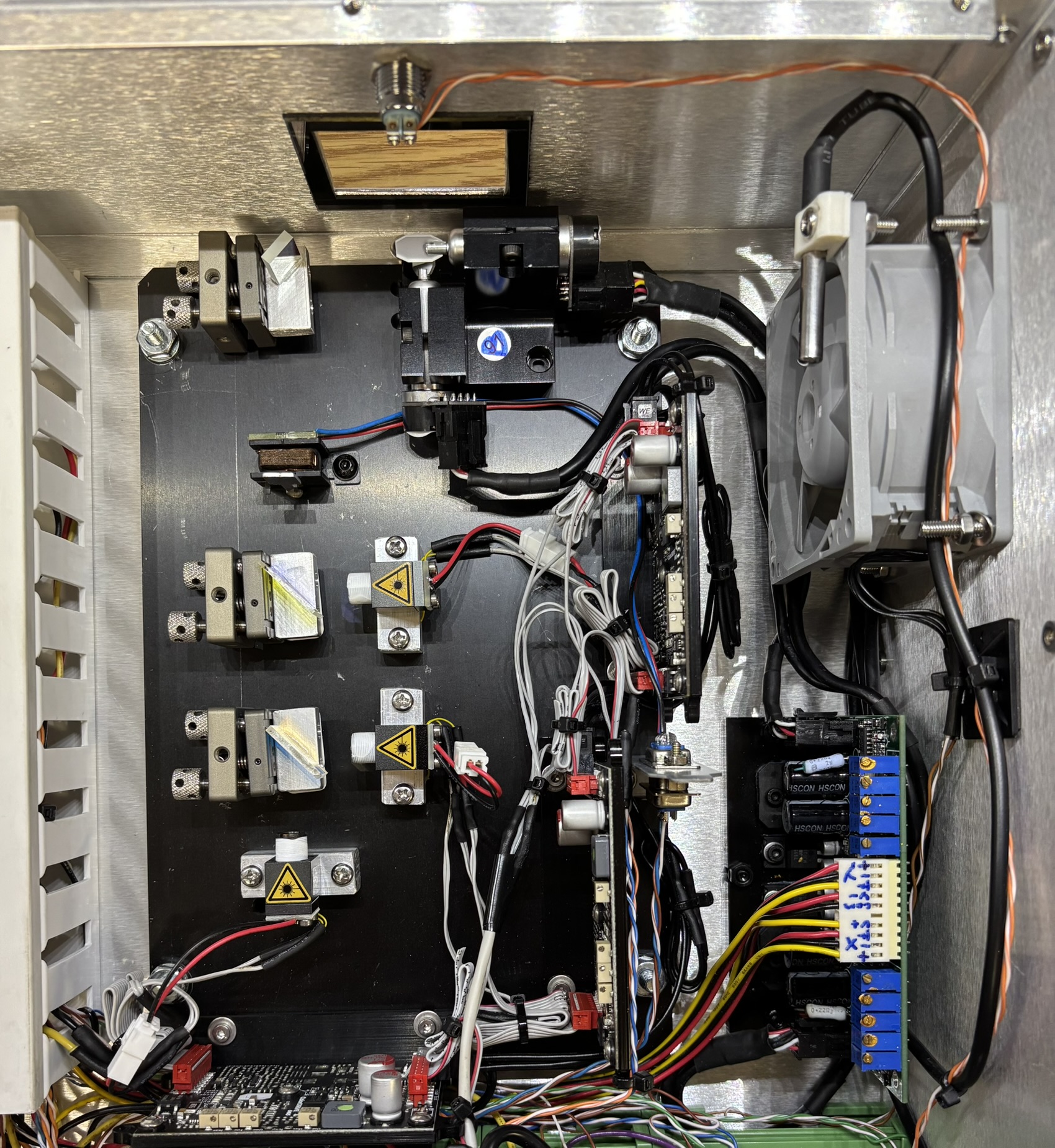
This image primarily focuses on the optical table and diode drivers, but also contains the exhaust fan and thermal probe mounted in front of the fan. The scanner (galvo) amplifier card is secured to the base of the casing below the fan. The optical table is a piece of anodized aluminum about 1/4-inch thick. Mounted to the optical table are the three diode drivers (ColorDRIVE One from Live Lasersystems), diode blocks, kinematic mounts, dichroic filters, beam shutter (Eye Magic NanoAct), and the scanners (DT-30). The laser diodes used are listed below along with specifications.
- RED - Sharp GH0637AA2G (700mW, 638nm)
- GREEN - Nichia NDG7475 (1000mW, 520nm)
- BLUE - Osram PLTB450B (1600mW, 450nm)
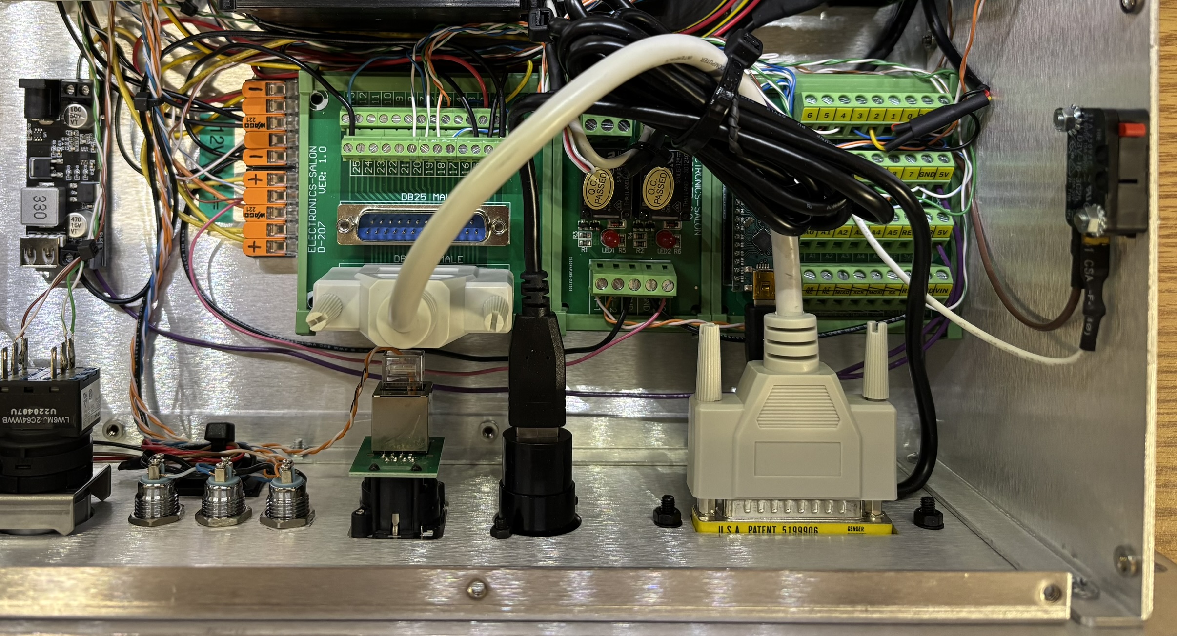
This is the control and input section. There are three off-the-shelf DIN rail mount modules that make up the distribution board and internal controller. On the left, a DB-25 breakout board is connected via a short jumper cable to the ILDA input connector on the control panel. This board breaks out all of the individual ILDA connections to the respective components within the laser system. In the middle is a small relay board. One relay is used to control the fan speed in a simple high/low arrangement. When the relay is not energized, the fan is connected to 12V DC and operates at maximum speed. The relay can be energized by the controller to switch the fan over to 5V DC (low speed). The other relay is for enabling the laser. When energized by the controller, it shorts the enable pins of all three diode drivers to ground to enable laser emission. On the right is an Arduino Nano installed in a DIN rail breakout board. This is referred to as the LSSM (Laser Safety System Monitor) and is responsible for monitoring the status of all interlocks and the system temperature. If the temperature is out of range or any interlock is opened, the controller will de-energize the laser enable relay and prevent emission. The LSSM can also de-energize the fan control relay to force the fan to run at full speed in the event of an elevated but not critical system temperature. Mounted to the case all the way to the right is the top cover interlock switch that prevents laser emission when the cover is removed.
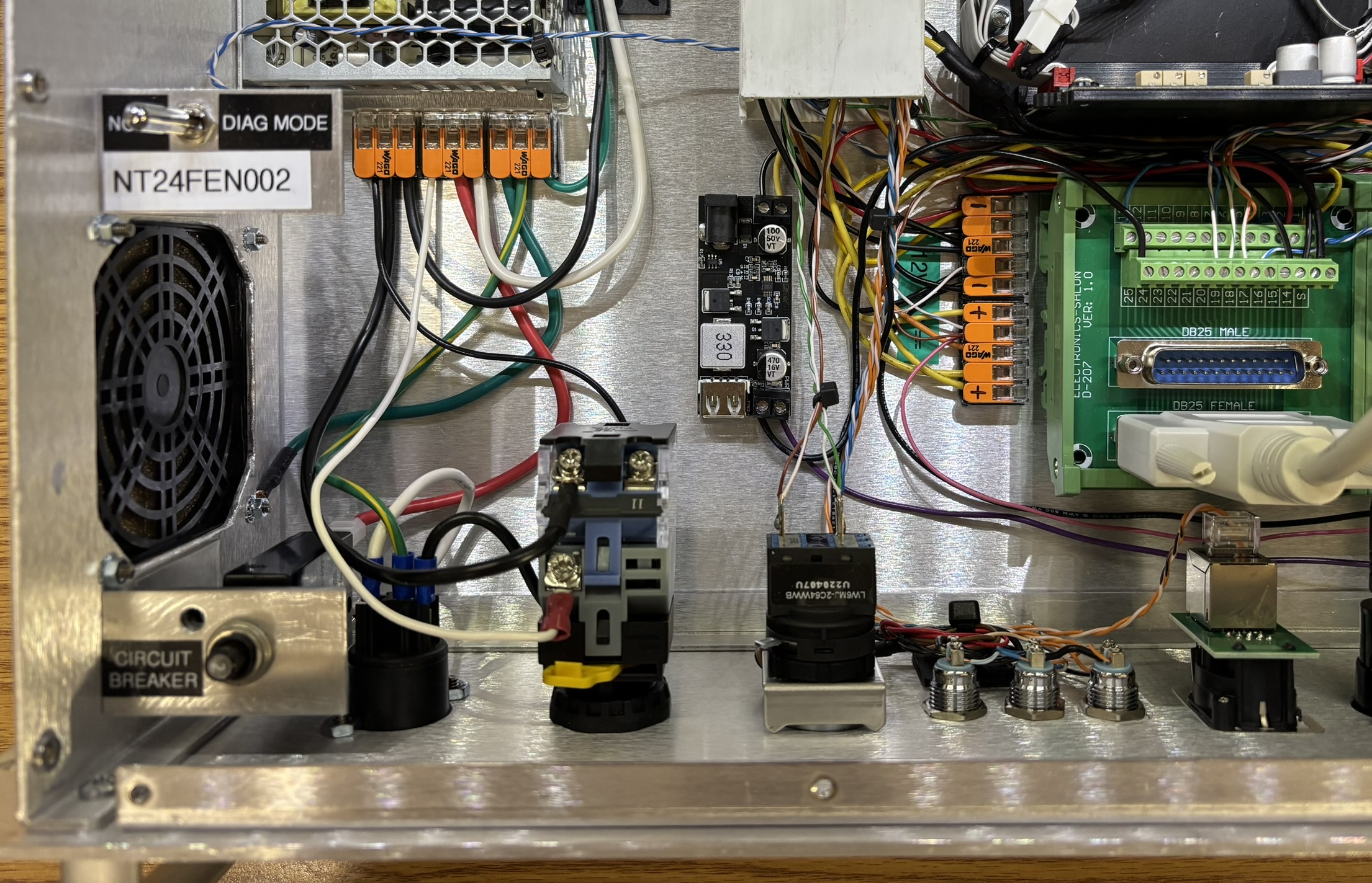
This picture shows the back side of the control panel and components. There is a circuit breaker on the AC input side that will trip if the system draws excessive current. There is also a diagnostic mode toggle switch that connects to an input on the controller. This can be customized as needed, but is generally used to test the fan at high speed or bypass interlocks and the CDRH delay during service.
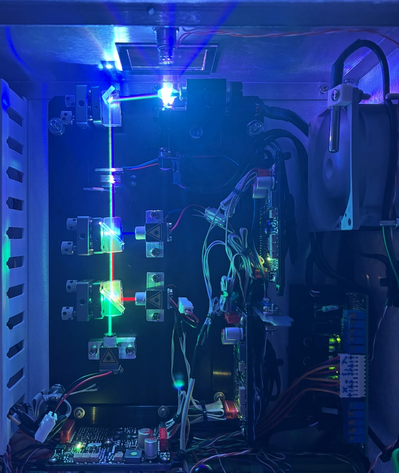
The image below showcases the beam path on the optical table. Green laser light is emitted from the diode, passes through the two dichroic filters, bounces off a first surface mirror at a 90 degree angle, and hits the scanners. Red laser light reflects off a dichroic filter and combines with the green beam towards the first surface mirror and scanners. Blue laser light reflects off of another dichroic filter and combines with the green and red beams towards the first surface mirror and scanners. The beam shutter will block all three beams before thy arrive at the first surface mirror when it's not energized. The position and angle of the first surface mirror needs to be adjusted, as it's not completely in line with the X scanner. Laser light should reflect at as close to a 90 degree angle as possible.
See below for some useful resources that helped us design and build this product!