Overview
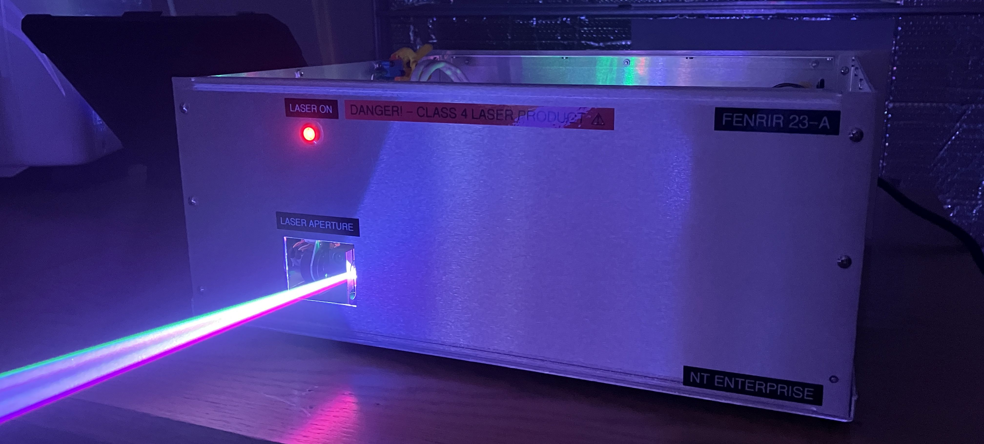
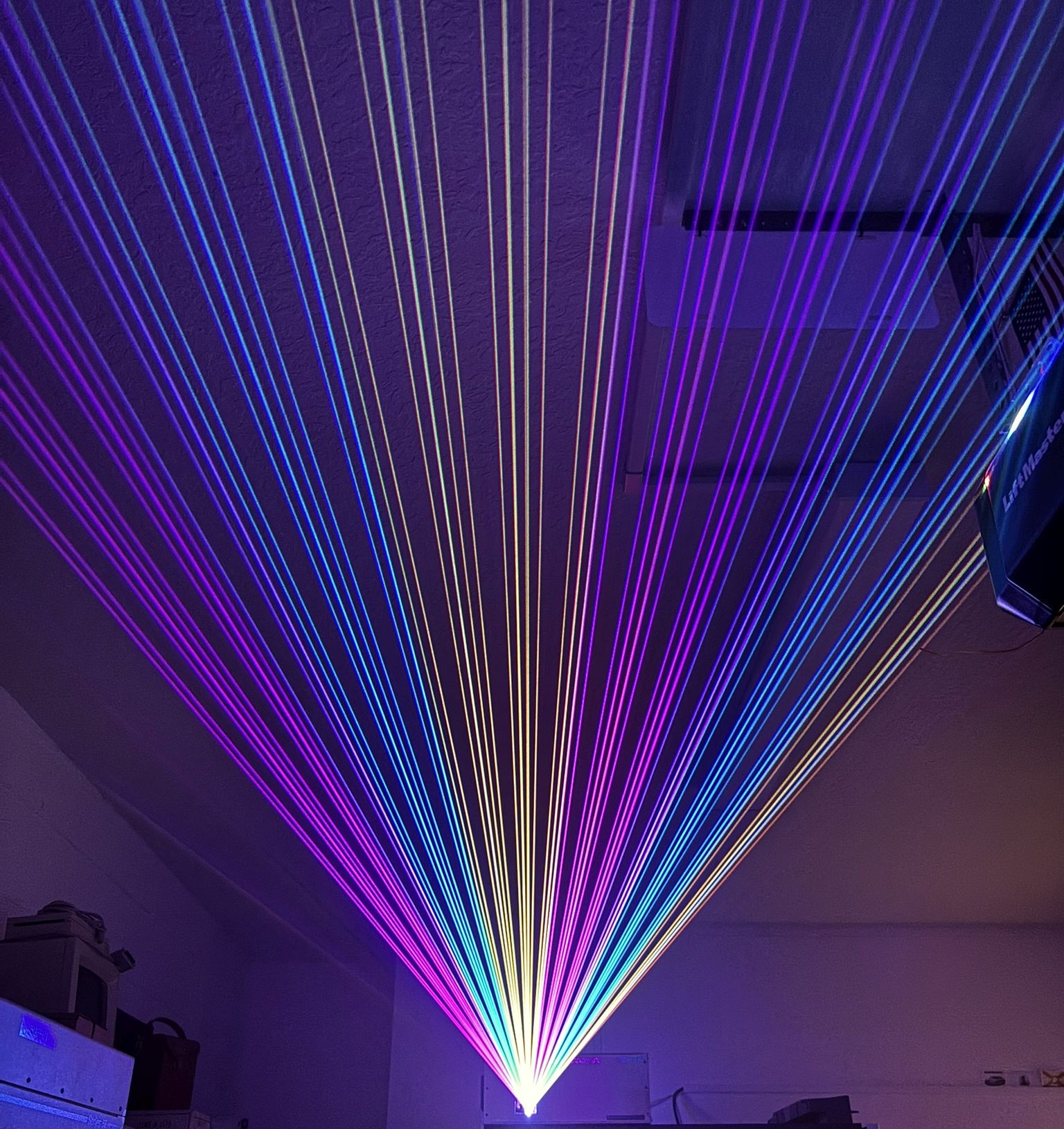
Directed Energy Systems is proud to present the FENRIR 23-A as our first fully-functional laser show projector capable of astonishingly bright and vibrant laser output, combined with the reliability and stability required by the most demanding entertainment environments!
We started this project with the intention of designing and creating a less expensive, but capable laser show projector. Throughout this process, we learned that the parts required and complexity of assembly are what cause commercial laser show projectors to be so expensive. Our unit ended up costing around the same in parts as a mid-range laser show projector from a reputable vendor, such as the UNITY RAW 1.7, which costs around $1,150 as of 2023. Ours was not far off just in parts, not to mention the many hours required for assembly and calibration.
Regarding the name and model number, a Fenrir is a mythological creature best described as an evil, monstrous wolf. Aside from being a cool name, we believe that it embodies the sinister capabilities of this laser projector as well as its rugged design! The number 23 indicates the year of production, so 2023 for this unit. The letter A is a revision indicator. Since this is our first prototype, it's revision A.
This write up will cover detailed specifications of this unit as well as the build process. Below are some quick specifications for reference:
- Full color RGB (3 total laser diodes)
- Around 1100 mW of total output power (combined red, green, blue)
- Analog modulation of diode drivers
- 25,000 points-per-second scanners
- Standard ILDA input, no built-in show card
- Active cooling by case fan, this unit is not equipped with TECs
- External interlock connection, key-switch, emission indicators
- Dedicated controller for monitoring and interlocks
Enclosure
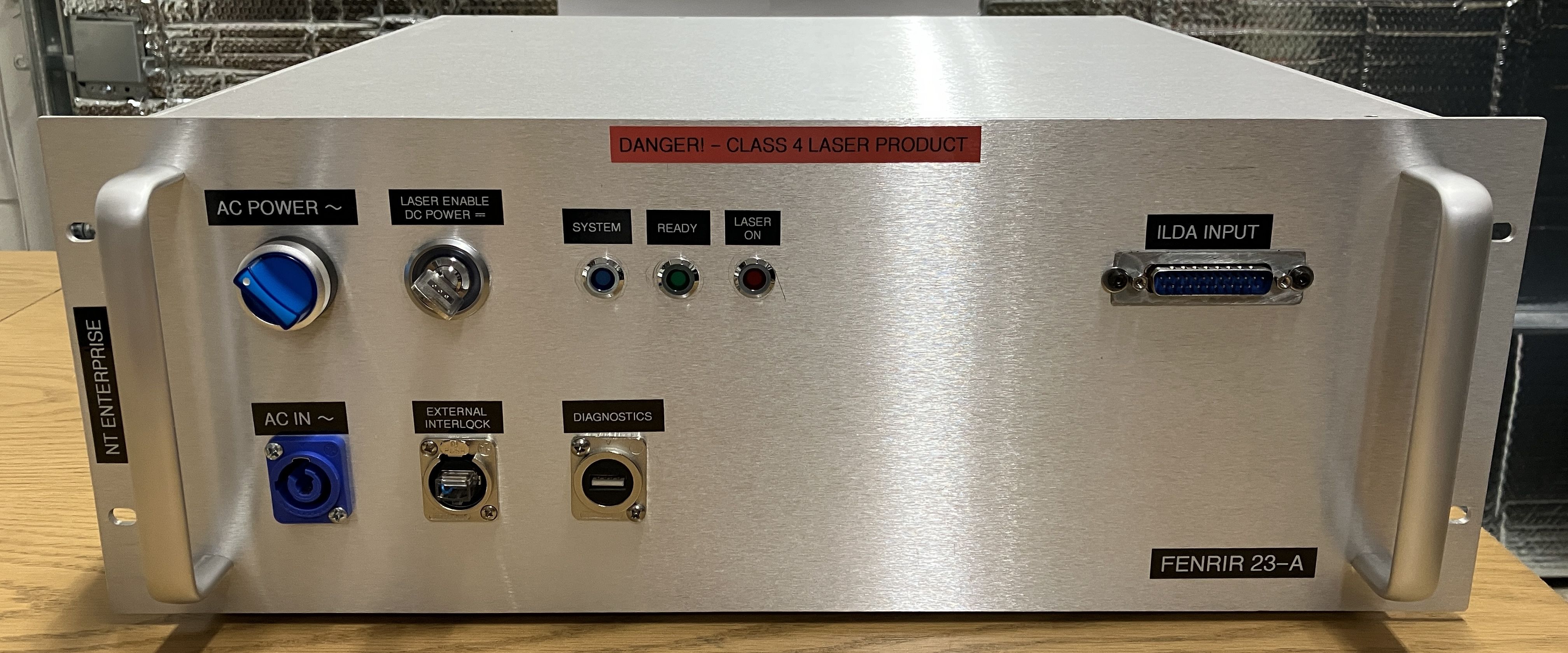
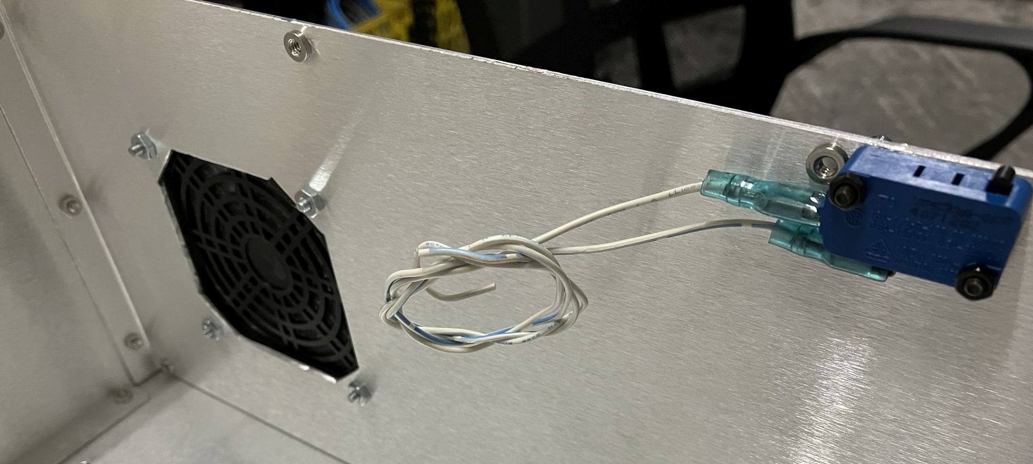
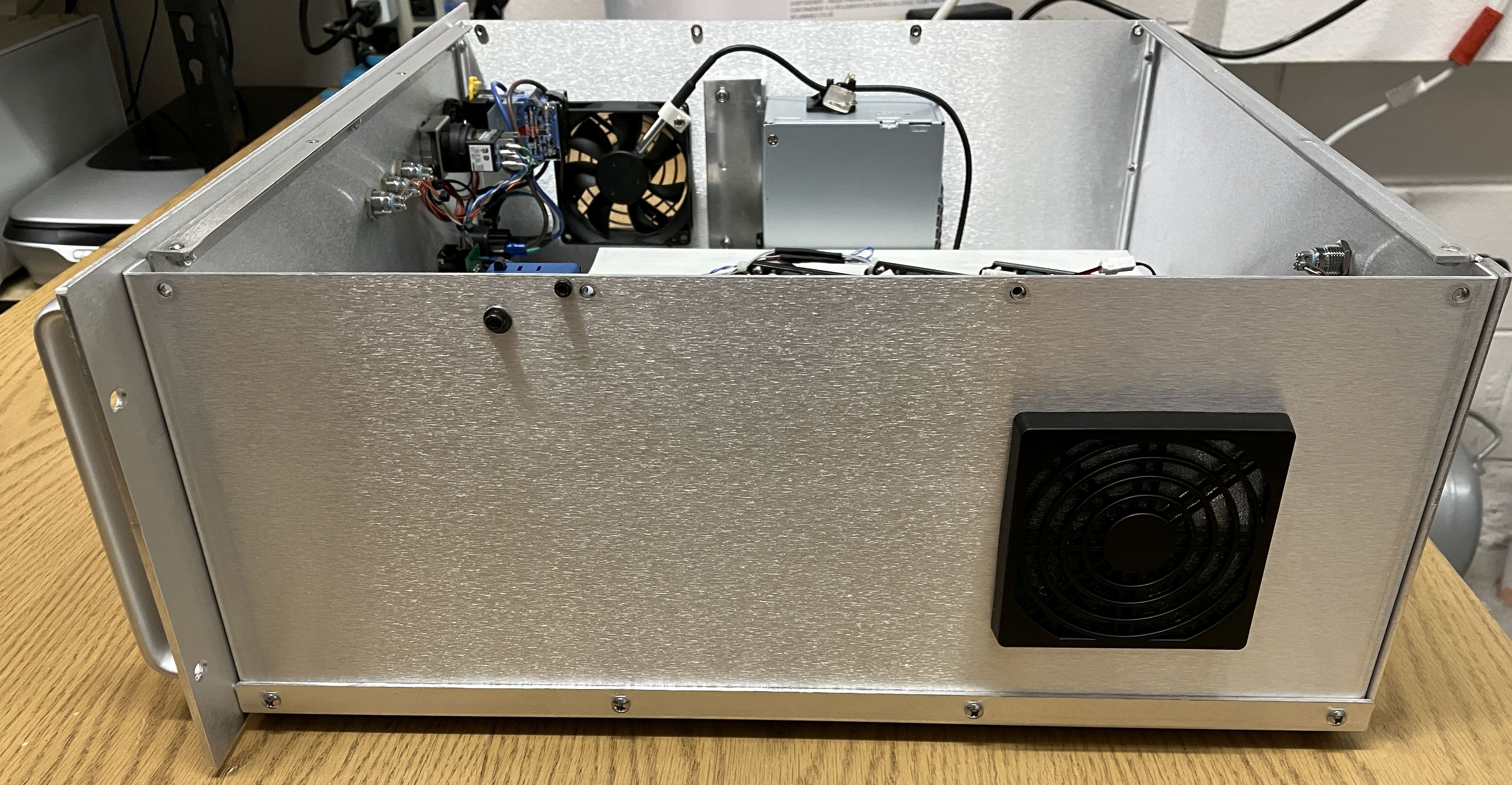
Starting with the outer casing, we chose a 4U aluminum rack-mount enclosure with no pre-cut openings. These are often used for making custom audio amplifiers or other rack-mount equipment. It was reasonably priced, shipped quickly on eBay, and was large enough to accommodate all of the required components while still allowing for decent working room. Aluminum is also relatively easy to machine and cut. A drill was used for the round openings for mounting screws, switches and connectors. A Dremel tool was used to cut square and rectangular openings for the laser aperture, case fan, and ILDA connector. The case assembles nicely in sections which makes it easy to remove individual panels for machining. We added some rubber feet to the bottom of the case. Most laser show projectors also include a mounting bracket, but that was not necessary for our use case.
Optical Table
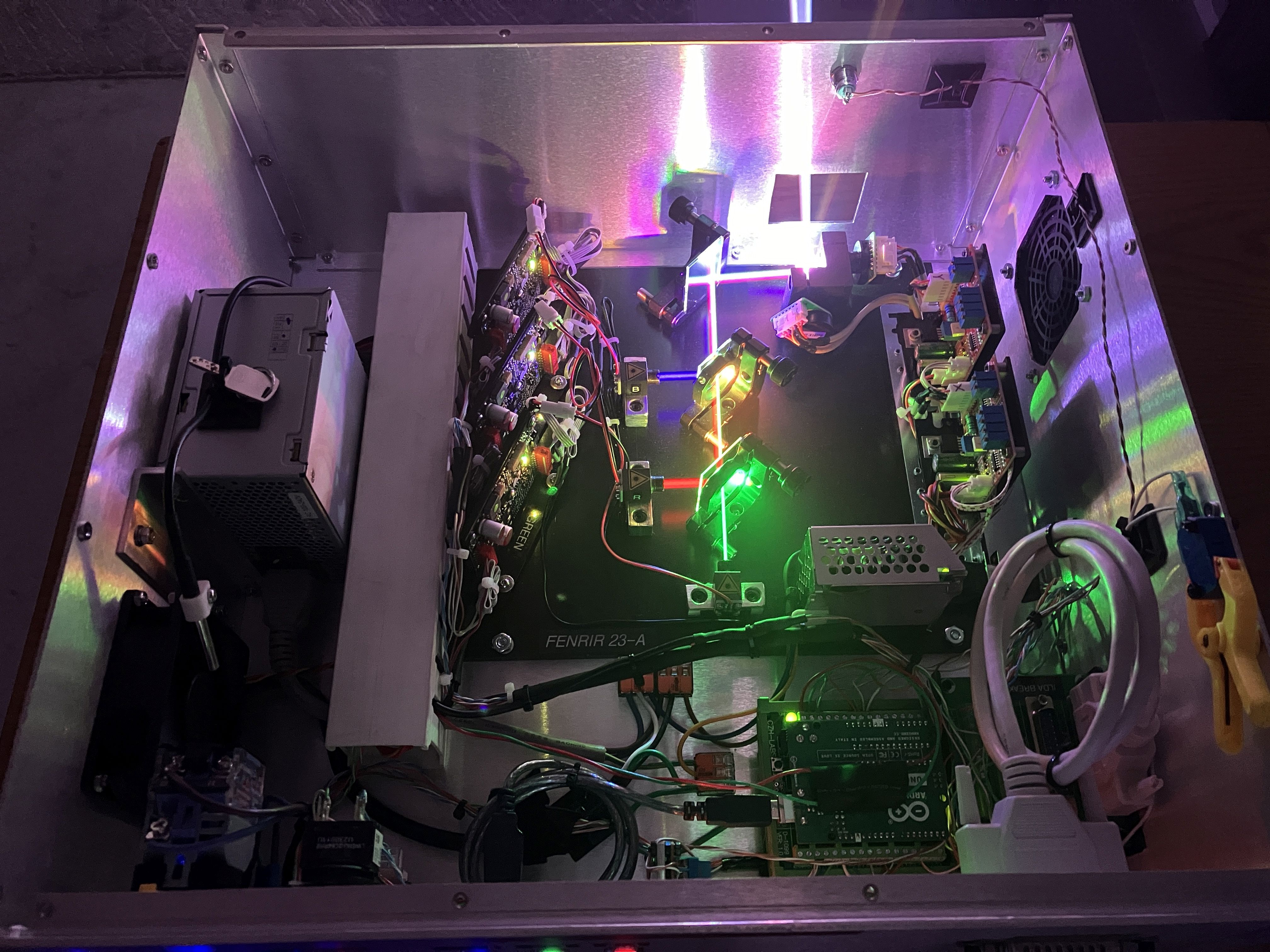
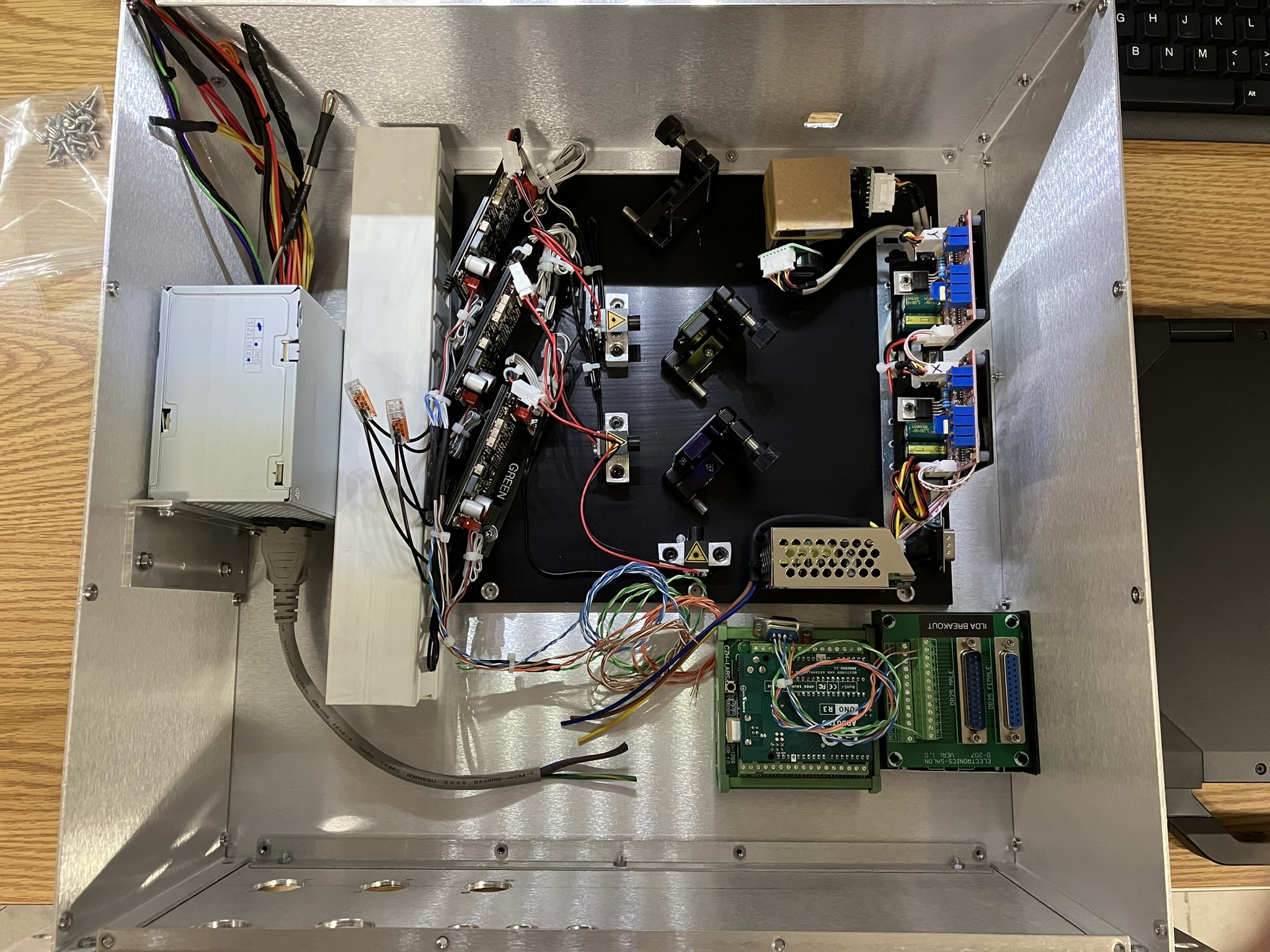
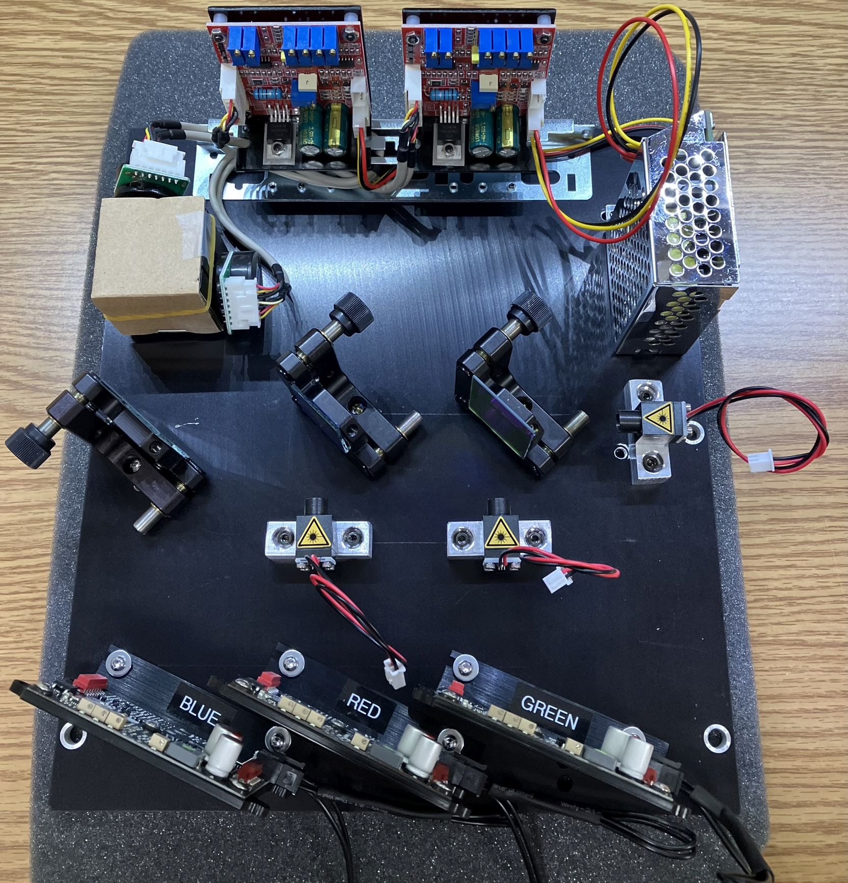
The optical table is a 1/4 inch thick piece of aluminum that was salvaged from another project. All optical components including laser diode modules, galvo scanners, dichroic filters and mirrors along with the galvo amps, galvo power supply, and diode drivers are mounted to the optical table. All holes drilled through the aluminum plate were countersunk on the bottom to ensure screw heads and nuts are flush with the bottom surface.
Control Panel
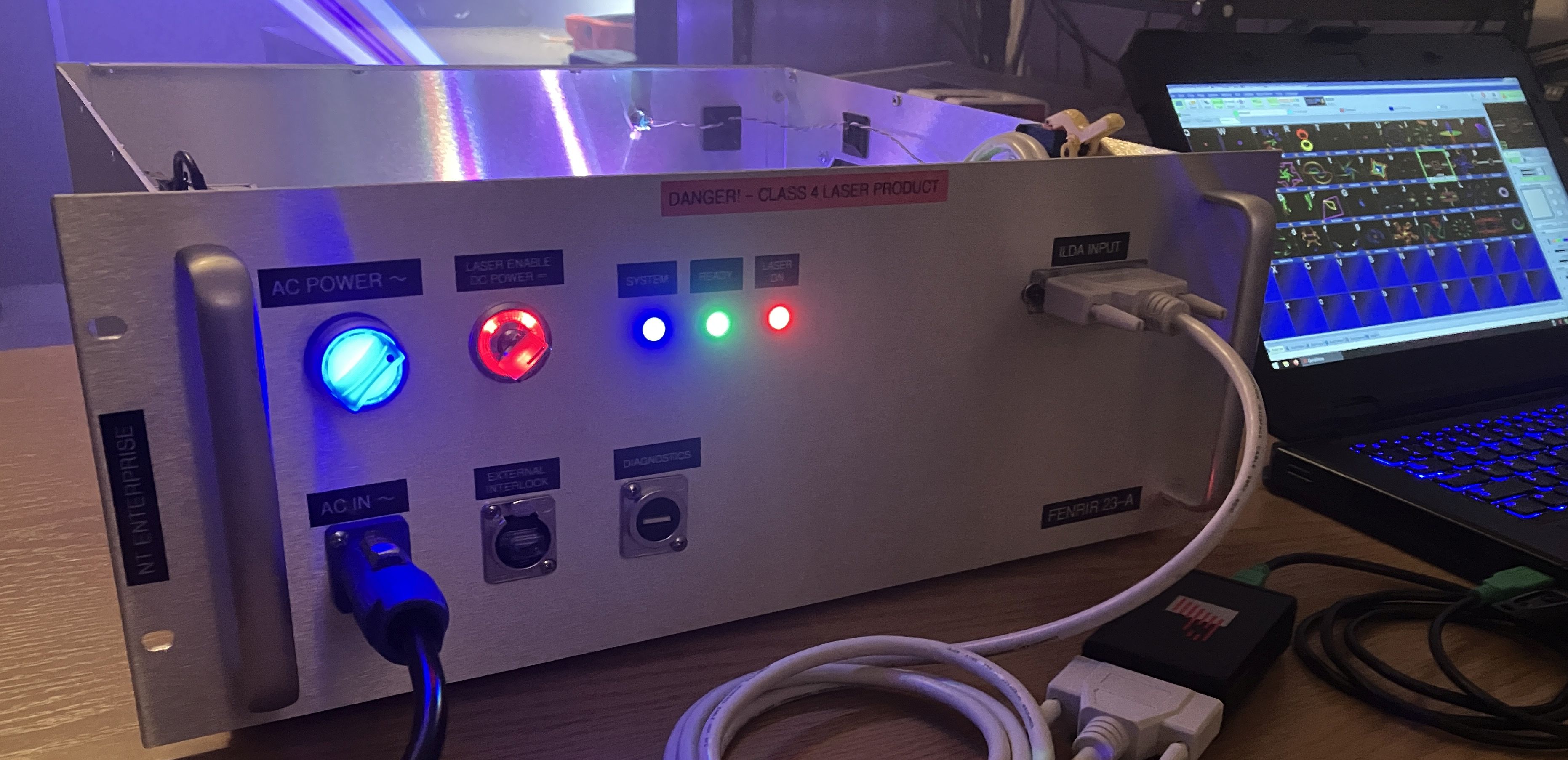
The control panel of the FENRIR 23-A is straightforward and only includes the essentials. Starting from left-to-right on the top row is the power switch (rotary, illuminated), interlock key-switch (illuminated), system status indicator (blue LED), "ready" indicator (green LED), laser emission indicator (red LED). On the bottom row is the AC power input, external interlock input, and USB connection for diagnostics and controller firmware updates. The ILDA input is located on the right side of the control panel near the handle. The power output and ILDA output connectors for daisy-chaining were omitted as they were not needed for our use case, but they will likely be included in future revisions. More details about the parts used for the controls and connectors are below.
AC power switch - blue illuminated 2-position rotary switch, YIJIA (Ali Express)
Interlock key-switch - a rather expensive choice, but the most high end control you can buy, LW Silhouette Series from IDEC
Status indicators - Generic panel mount LEDs
AC input connector - Neutrik PowerCON twist-lock connector
External interlock - Neutrik EtherCON RJ-45 connector
Programming port - panel mount USB connector designed to occupy the same footprint as the Neutrik connectors
DC Power Supply
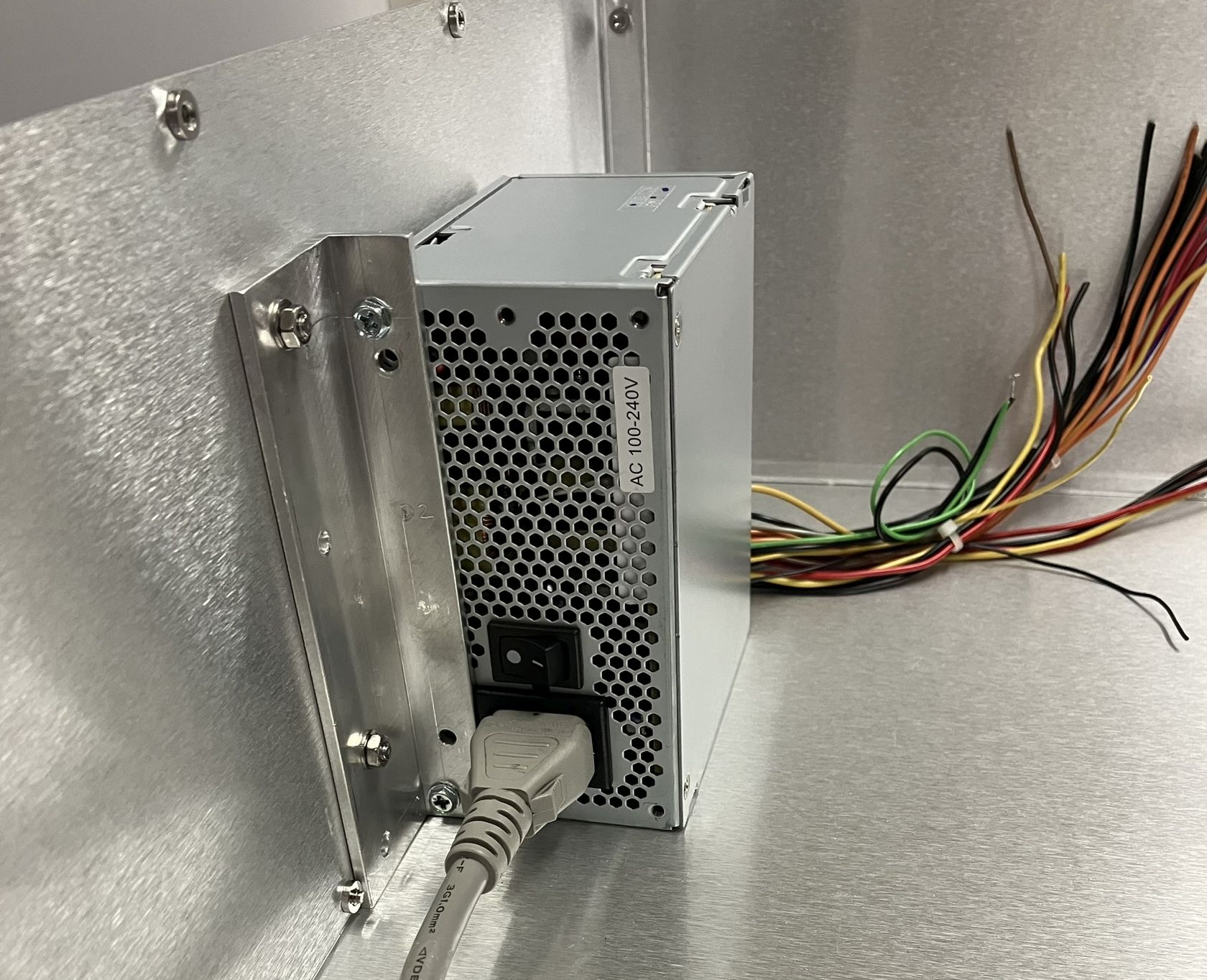
DC power is supplied by a Delta Electronics 600 watt micro-ATX power supply that was salvaged from a security camera DVR. It's a bit overkill since it only powers the diode drivers, controller, and fans, but it was readily available. It also has a standby rail, a power enable circuit, and includes both 5V and 12V rails. The 12V rail powers the 3 diode drivers and the fan, the 5VSB (5-volt standby) rail powers a voltage booster module, which feeds the input of the controller even when the interlock is open. The enable circuit of the ATX power supply is connected to the interlock key-switch which ties it to ground when the interlock is closed. This provides another layer of safety ensuring the diode drivers don't even receive DC power when the interlock key-switch is not engaged. The scanners are powered by their own +15V/-15V power supply.
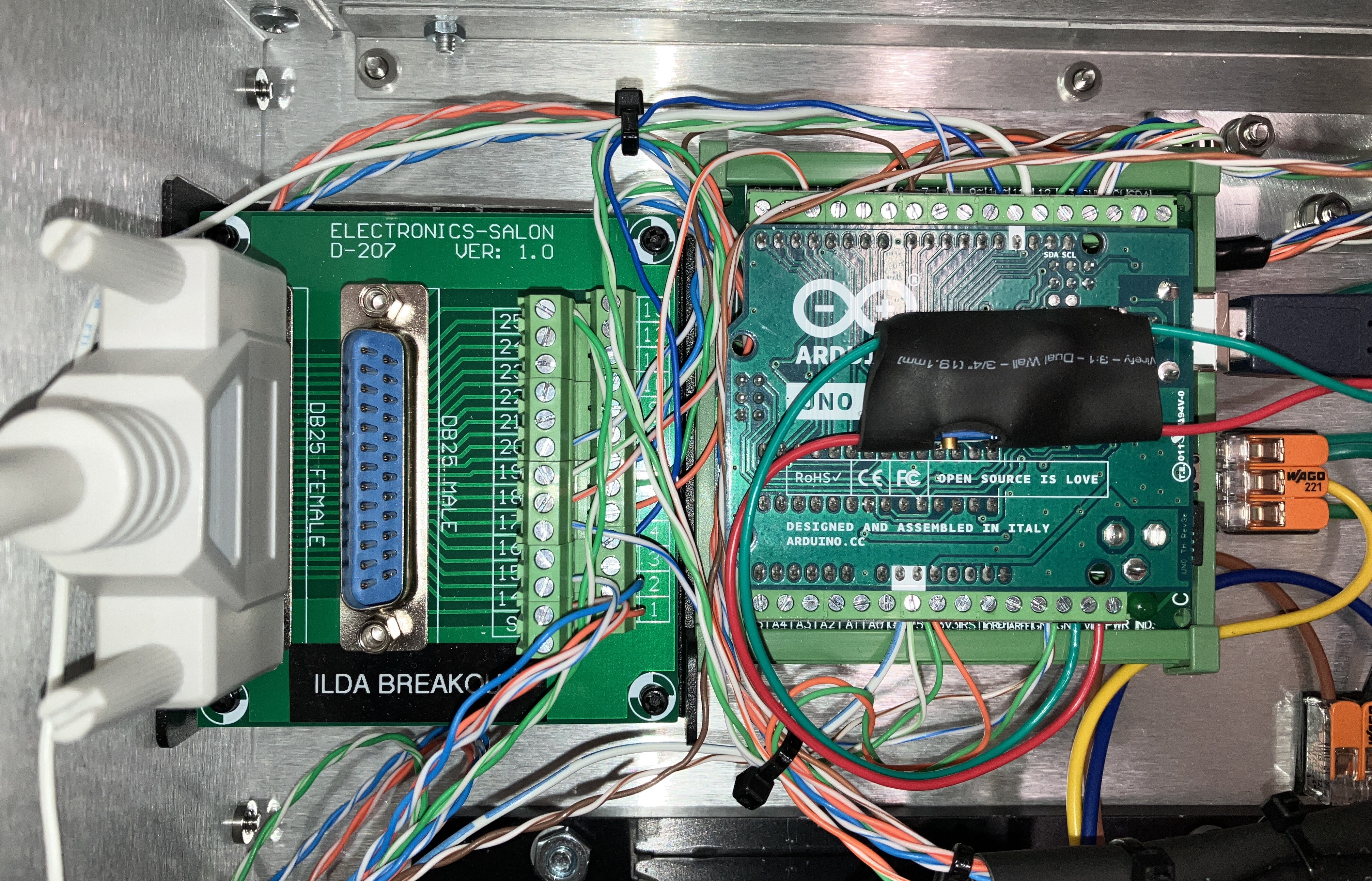
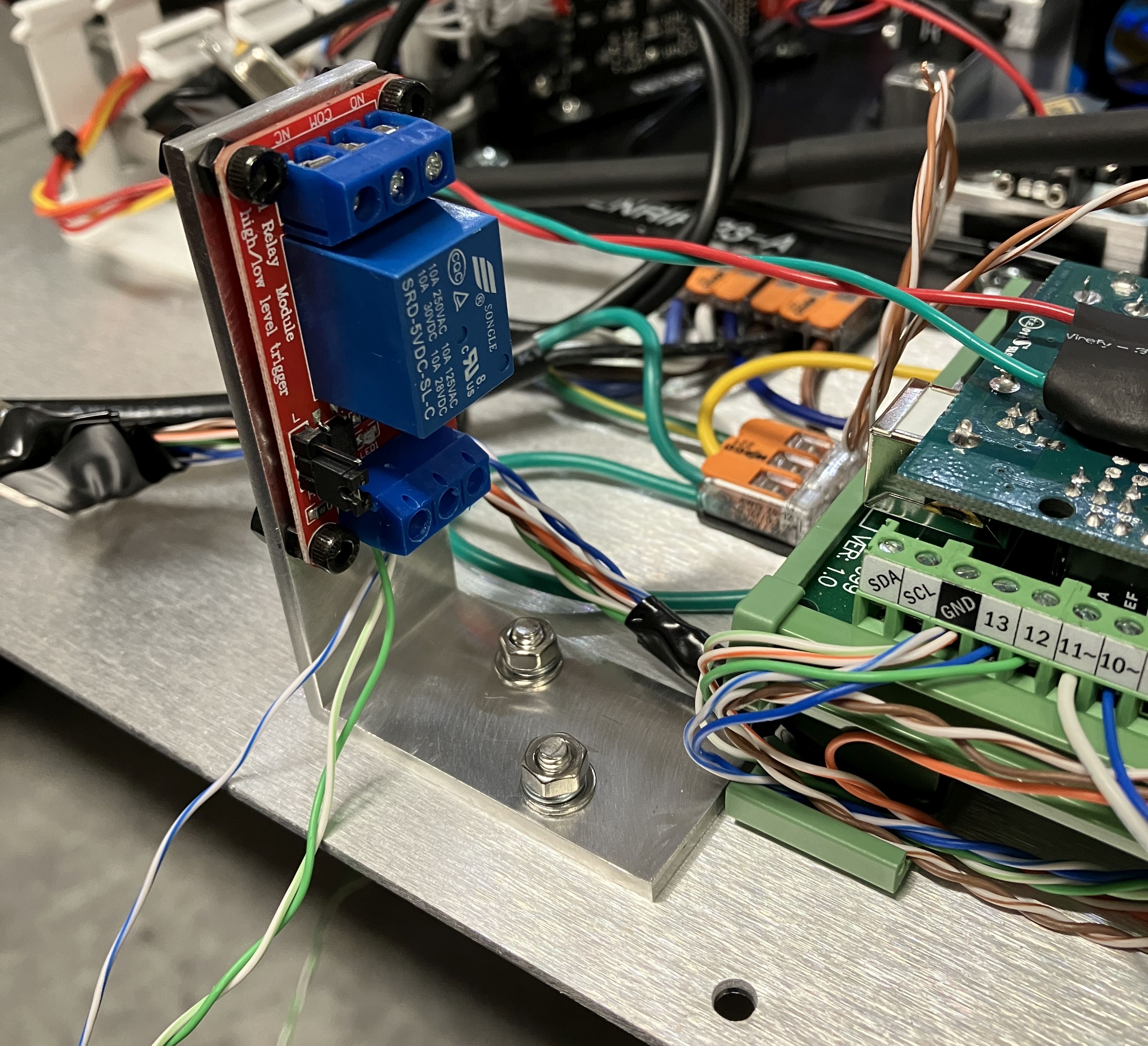
Internal Controller (LSSM)
This laser system has a dedicated internal controller called the "Laser Safety System Monitor", which has several critical functions. The controller hardware is an Arduino Uno installed on a breakout board, mounted to a piece of DIN rail next to the DB-25 ILDA breakout board. The primary function of the LSSM is to manage the interlocks. It has inputs for the key-switch, external interlock, case interlock, and ILDA interlock. The controller will only enable laser output if every interlock is closed. If an interlock is opened, the controller will immediately stop laser output. The LSSM controls a relay that bridges the interlock input signal of the diode drivers to ground. Additionally, the LSSM also monitors the system temperature and will disable laser output if the temperature exceeds a specified threshold. Lastly, the LSSM can be used for diagnostics of the laser system and to monitor connected components. The USB port on the control panel connects directly to the USB port of the Arduino and can be used for diagnostics or firmware updates. The LSSM is powered by a boost converter, which receives power from the 5VSB rail of the DC power supply. It's worth noting that the VIN PIN of the Arduino has an input voltage range of 7-12V DC. We used the boost converter module to step up the 5VSB rail to 9V to sufficiently power the Arduino.
Interlocks
The FENRIR 23-A includes several safety interlocks, each independently connected to the LSSM (Arduino). First is the external interlock, which is the RJ-45 connector on the control panel. Bridging pins 1 and 3 of the RJ-45 connector will satisfy the external interlock. Next is the case interlock which is a micro-switch mounted to the side of the aluminum case. When the top cover is securely installed, it will depress the micro-switch, completing the case interlock circuit. Next is the interlock key-switch which is just the key-switch on the control panel. It must be rotated to the right position to complete the circuit. Lastly is the ILDA interlock, which is satisfied when a laser DAC is connected to the ILDA port (pins 4 and 17 of the ILDA DB-25 connector bridged). Additionally, the key-switch is connected to the ATX power supply's power enable circuit. This provides a separate circuit to ensure all laser output is stopped when the key is turned off, even in the rare event that the LSSM were to malfunction. Emission indicator LEDs on the front of the case and on the control panel clearly show when the system is capable of emitting laser radiation. The interlock relay which controls the diode drivers, is mounted on a right-angle bracket in close proximity to the LSSM.
Thermal Monitoring
Thermal monitoring is provided in two ways. First, each diode driver has an NTC thermistor connected and mounted in close proximity to the respective laser diode module. If the NTC thermistor temperature exceeds a specified threshold, the diode driver will reduce output power, and if the threshold continues to be exceeded, it will disable laser output completely. Each individual diode driver and diode module has its own NTC thermistor. Additionally, the LSSM has a probe that monitors the temperature of the air right before being exhausted by the cooling fan. If it exceeds a certain threshold, the LSSM will open the interlock circuit and disable laser output. A case fan ensures fresh air is circulated through the enclosure and exhausts warm air. The intake opening has a filter installed to prevent dust from entering the enclosure. There are no thermoelectric coolers (TECs) installed in this unit as it was not needed for our use case. The system is stable as long as it's operated in a climate-controlled area.
Laser Diodes, Optics, and Optomechanics
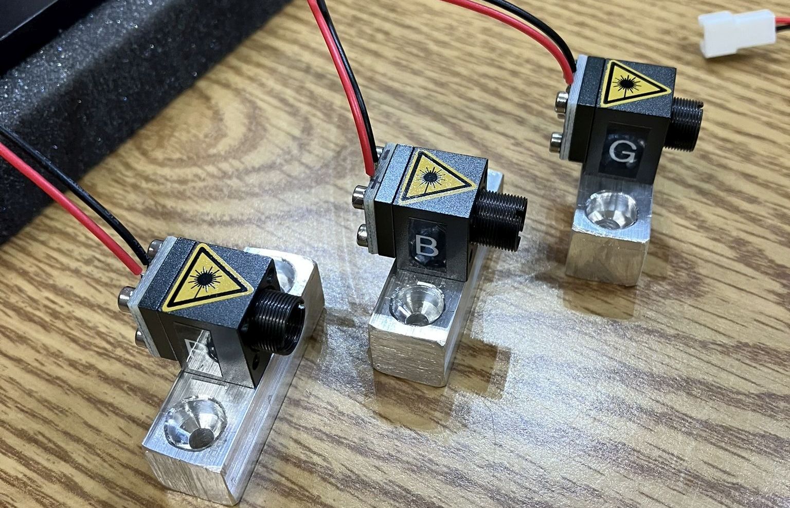
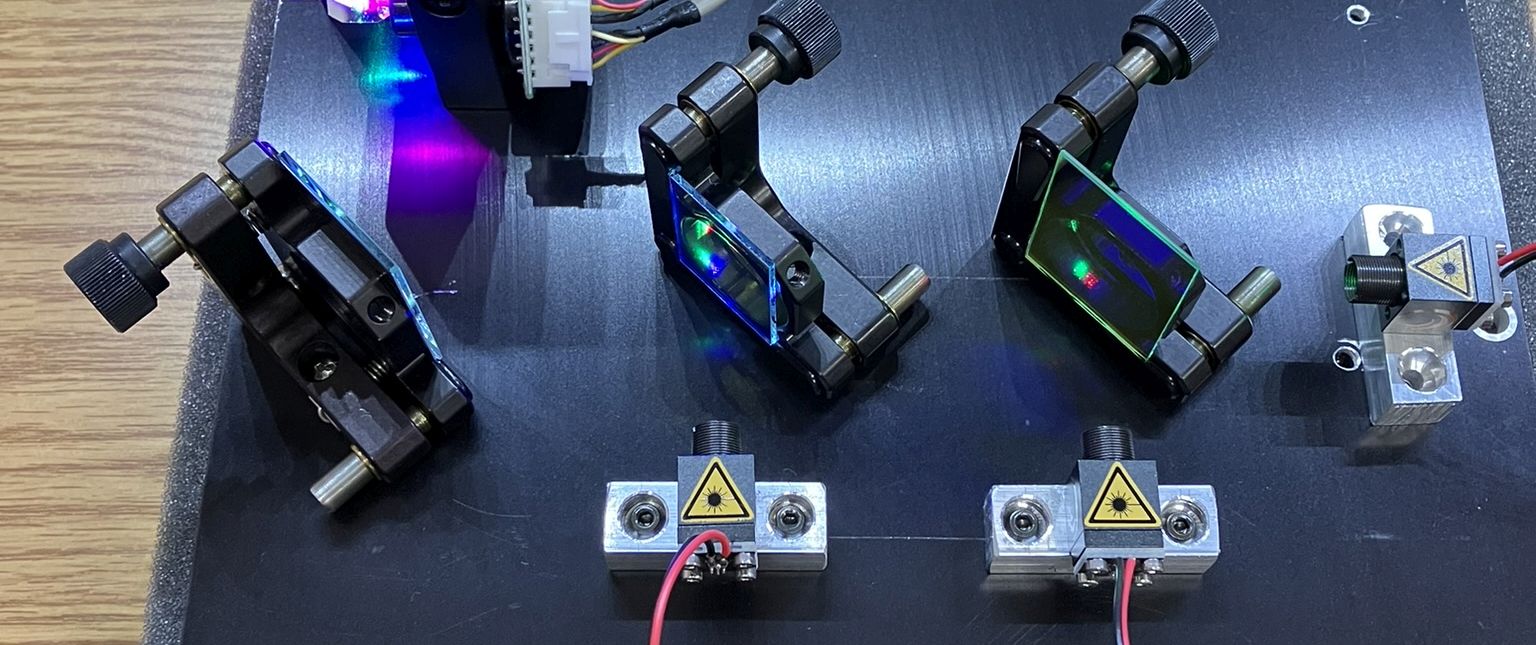
The laser diodes used in the FENRIR 23-A are listed below. Each diode is installed in a square mounting block (Lasertack PD-01158) with a threaded opening for a DTR G-8 lens. The laser diode blocks are mounted to custom-machined 1/2 inch square pieces of aluminum. This mounting system provides for flexibility and elevates the laser diodes to the proper height for the optics. Dichroic filters are used to combine the beams, they were salvaged from a video projector along with the small mirror which directs all beams into the galvo scanners. ThorLabs KM100 kinematic mounts are used for the optics. Each dichroic filter and the small mirror are all glued to their own kinematic mount. This ensures easy alignment in the future. All of these optical components are mounted to the optical table. The lenses were screwed into the diode mounting blocks, fine-tuned for optimal focus, and then secured in place with medium strength thread-locker.
RED - Sharp GH0637AA2G (700mW, 638nm)
GREEN - Nichia NDG7475 (1000mW, 520nm)
BLUE - Osram PLTB450B (1600mW, 450nm)
Laser Diode Drivers
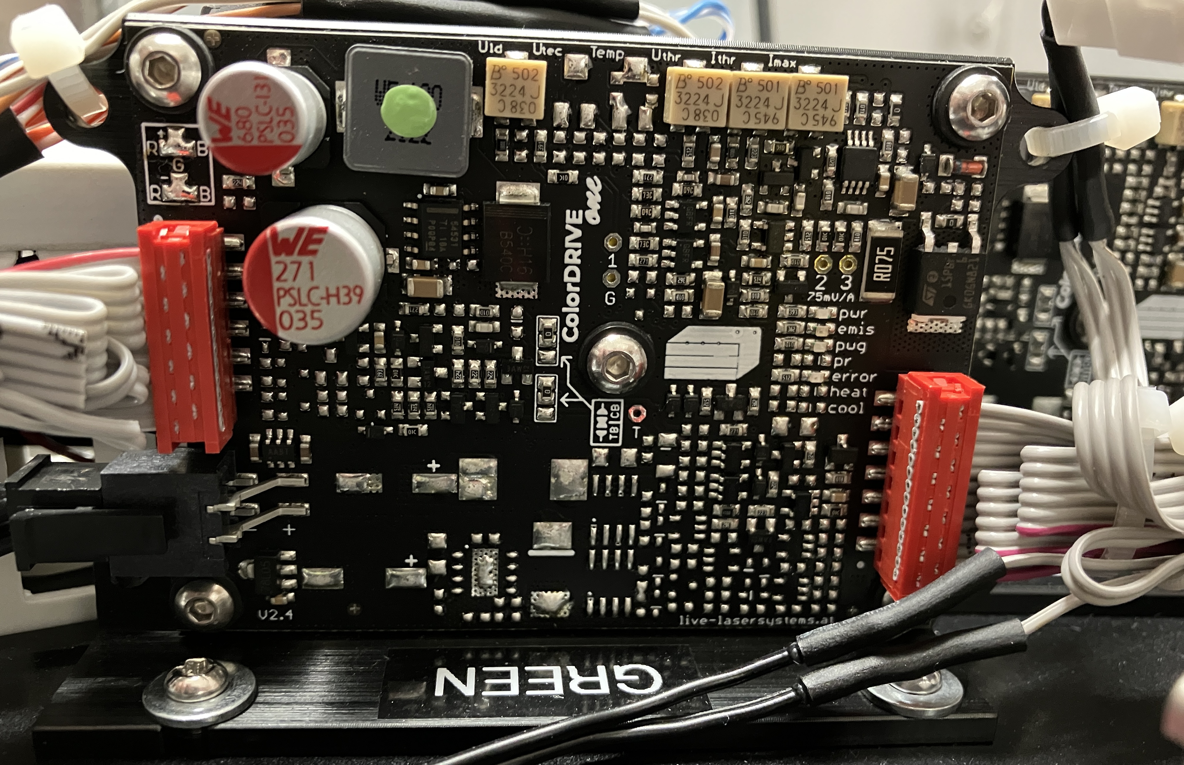
Each laser diode is driven by a ColorDrive One from Live Lasersystems. There are 3 drivers, once for each color laser diode. These are very versatile, compact, and reliable diode drivers. All tuning and adjustment is done via potentiometers on the driver board and test-points are used to measure critical values such as diode voltage and current. The manual is detailed and clear, making adjusting and using these drivers a pleasant process. They can even be ordered with built-in support for TECs but this was not needed for our system. The diode drivers receive DC power from the ATX power supply's 12V rail. The interlock inputs of each driver are connected together, in parallel, to the interlock relay. The LSSM controls the interlock relay to enable or disable laser output. The analog modulation input of each driver connects to its respective color output on the ILDA breakout board. Since we chose to only use one red laser diode, which is capable of a maximum output power of 700mW, the green and blue diodes are being significantly under-driven to ensure decent color. Future revisions will include two red diodes in order to utilize the full potential of the blue and green diodes.
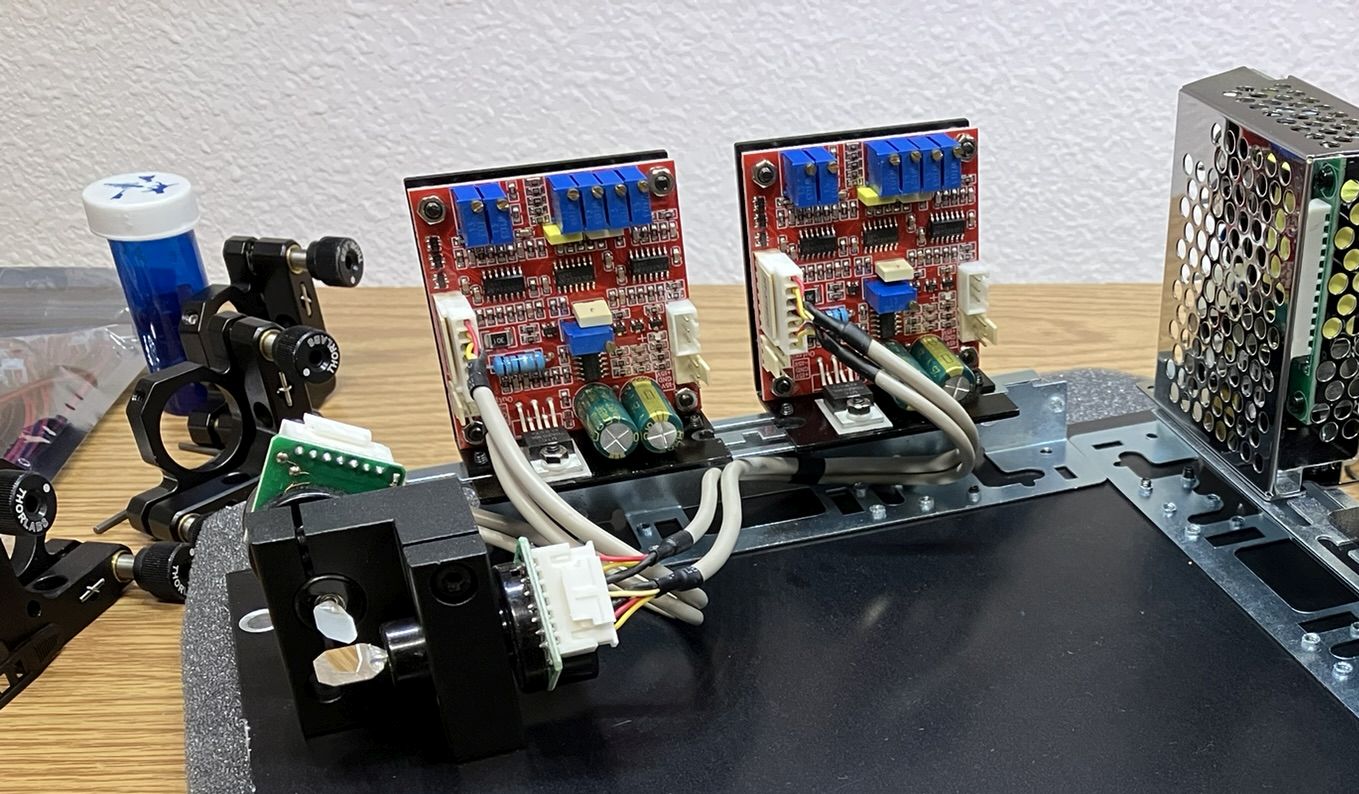
Scanners / Galvos
We have limited information on the galvo scanners that are used in this laser system. They were purchased online from eBay over a year ago and we were unable to locate any manufacturer or model information. It was originally sold as a kit including the galvo scanners, galvo amps, show card, and power supply. We know the scanners are capable of around 25,000 points per second but not much else. While they are reliable and work well, we plan to eventually replace them with a set from a more reputable manufacturer.
Final Remarks and Planned Improvements
The images above may reflect the absence of an output window for the laser aperture. We are working on sourcing a suitable piece of glass to use as an output window. Having an output window and sealing it to the case is important to prevent dust from accumulating on the scanner mirrors and other optical components. All openings other than for ventilation should be sealed to ensure no dust enters the casing which can degrade the optical performance.
While building and testing the FENRIR 23-A, we took note of several areas for improvement. We look forward to applying these improvements to future revisions. Some of the planned improvements are listed below.
- More robust thermal management (TECs)
- Different lenses for beam focusing and optics for beam correction
- Potentially smaller case, would require a more compact power supply and overall component size reduction
- Manual or electronic beam shutter
- ILDA output and AC power output for daisy-chaining
- LCD display connected to LSSM for more detailed monitoring and status display
- Machined component quality can be improved by using a drill press and more advanced cutting tools
- 2 red laser diodes for a more intense output
Useful links related to this project