The Coherent CUBE is a self-contained direct-diode laser system that incorporates digital monitoring, control, and thermal management in a very small package. In this writeup, we will be focusing on the control boards and digital circuitry contained within the CUBE.
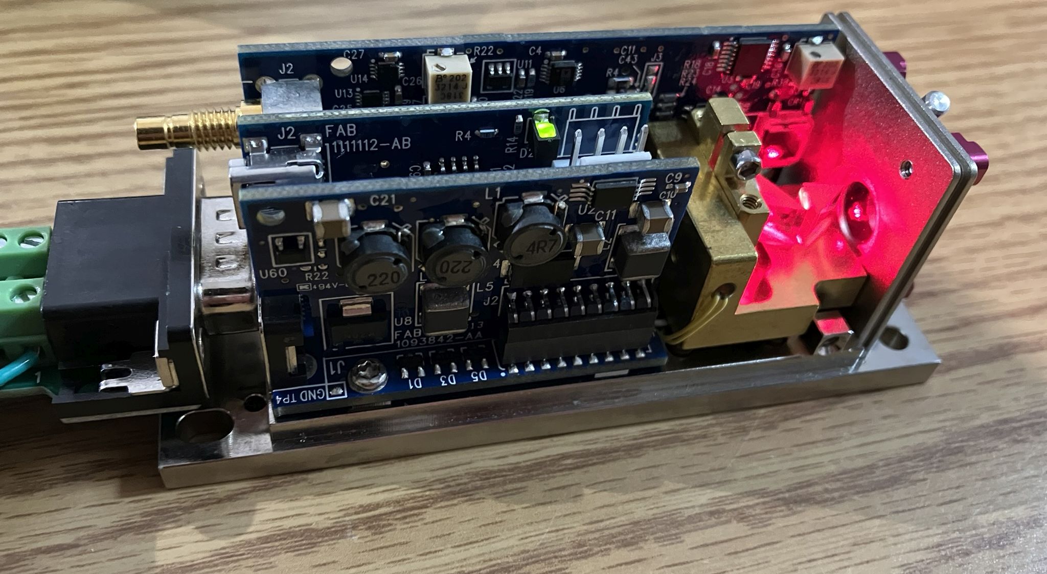
Contained within the casing are three individual circuit boards that share a common backplane/motherboard. Each board has a dedicated role and they all communicate over the backplane. This enables the CUBE to self monitor, and allows for external control and monitoring over an RS-232 serial interface.
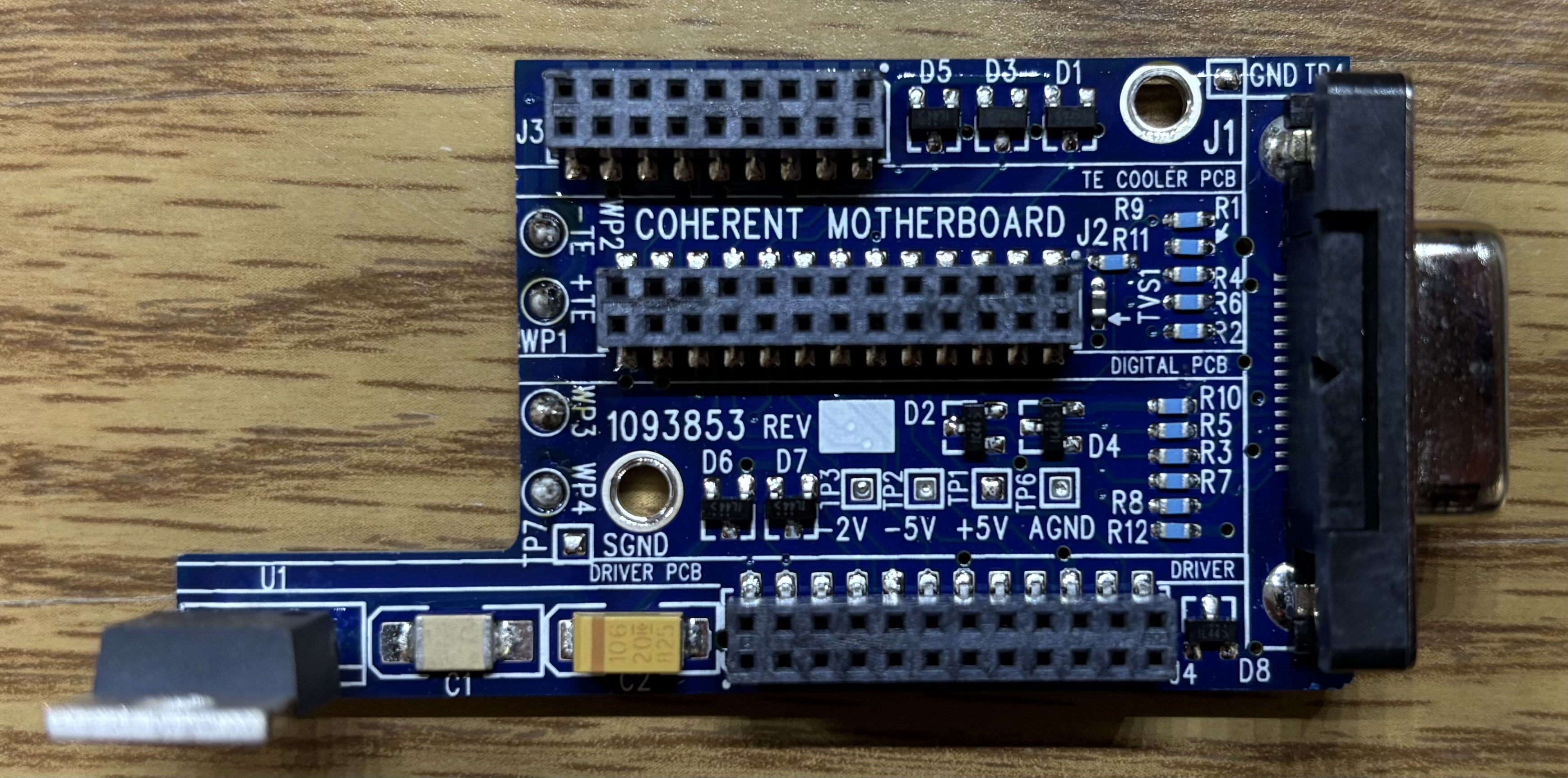
The backplane is referred to as the COHERENT MOTHERBOARD (1093853). It has three dual-row pin header connectors for the other boards to slot in perpendicularly. The DB-15 connector is mounted to the backplane for power input, external control, and the serial interface. Most of the other components on the backplane are just passives. There is a MIC29300-5.0WT linear voltage regulator mounted to the backplane near the slot for the diode driver board, labelled U1. Solder pads WP1 and WP2 are for the internal TEC, pads WP3 and WP4 are for the diode thermistor (diode temp reading in software).
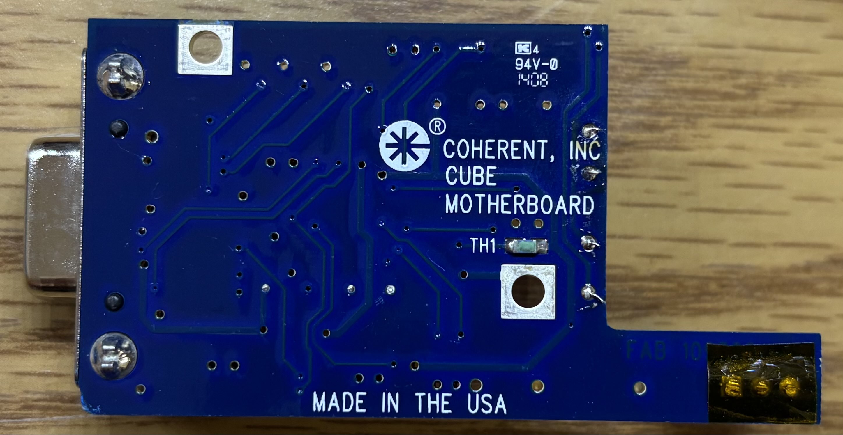
There's not much to see on the back of the board other than a small thermistor labelled TH1. This is called the baseplate thermistor in the software.
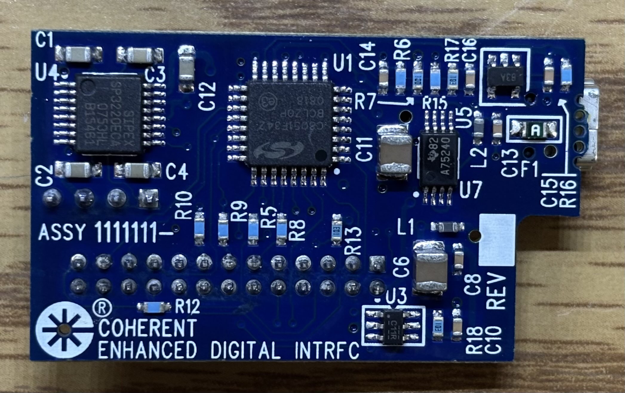
This is the ENHANCED DIGITAL INTERFACE board (1111111), which is responsible for all serial communication and storing laser parameters. It communicates via I2C to the other boards over the backplane. U4 is a SIPEX SP3220E RS-232 driver/receiver pair, which is used for serial communication. U1 is a Silicon Labs C8051F342 MCU with built-in USB, I2C, RAM, flash, and more. We suspect that the majority of the control program is stored in flash on this chip. Eventually, we would like to extract the MCU and read out the data from the flash. U7 is a TI SN75240 USB port transient suppressor. U3 is a SN74LVC1G11DBV AND gate.
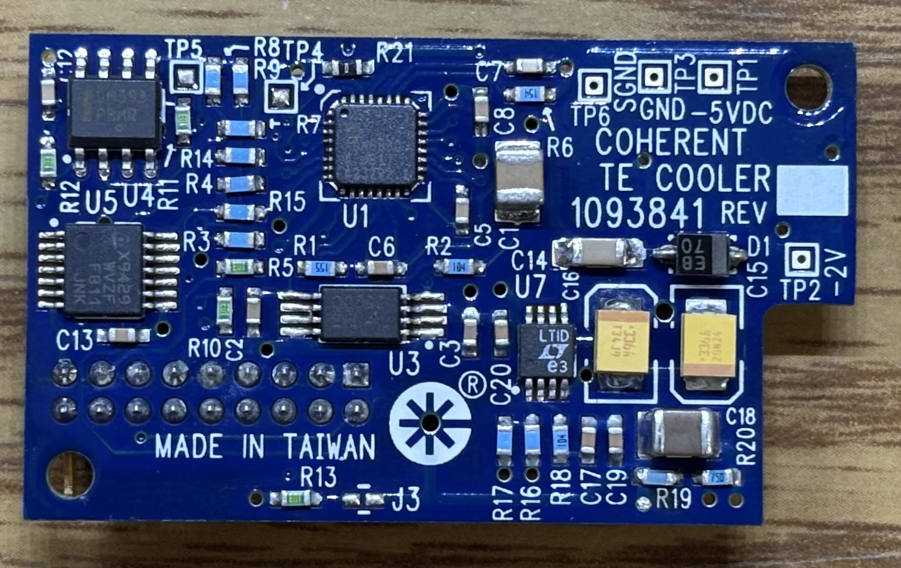
On the other side of the ENHANCED DIGITAL INTERFACE board are a few interesting components. The USB mini-B connector (J2) is exposed on the back panel of the laser head and provides the same functionality as the RS-232 interface over the DB-15 connector, just as a USB-to-serial adapter. However, drivers for the USB-to-serial chipset do not seem to work on any Windows operating system above Windows 7, so we recommend saving yourself the headache and just using the RS-232 pins on the DB-15 connector. The 4-pin connector (J3) is very likely an internal programming and diagnostic connector. It is only accessible when the top cover is removed and directly connects to the C2 debug and programming interface pins of the MCU on the reverse side. The EEPROM (U2) is where we focused significant effort. It's a Microchip 24LC16B 16K serial EEPROM, which we were able to de-solder and read with an external EEPROM programmer. The results were fascinating, but raised more questions. The EEPROM mostly contained the table of query and system control commands. It also contains a list of manufacturing commands, which are not available or even displayed during normal operation. We of course tried these commands on a functional CUBE laser, but it rejected all of them. The system probably needs to be in a programming or manufacturing mode for the commands to be processed. Figuring out how to enter this manufacturing mode is our next objective. View the HEX and ASCII dumps of the CUBE EEPROM by visiting the links below.

This is the TE COOLER board (1093841), which drives the internal TEC mounted between the diode block and the baseplate. U1 is an ADN8830 dedicated TEC driver. U2 is a Fairchild FDW2520C MOSFET. U4 is an LM393M comparator. U5 is a XICOR X9429 single digital potentiometer, which is most likely used to configure the TEC setpoint using a manufacturing command.
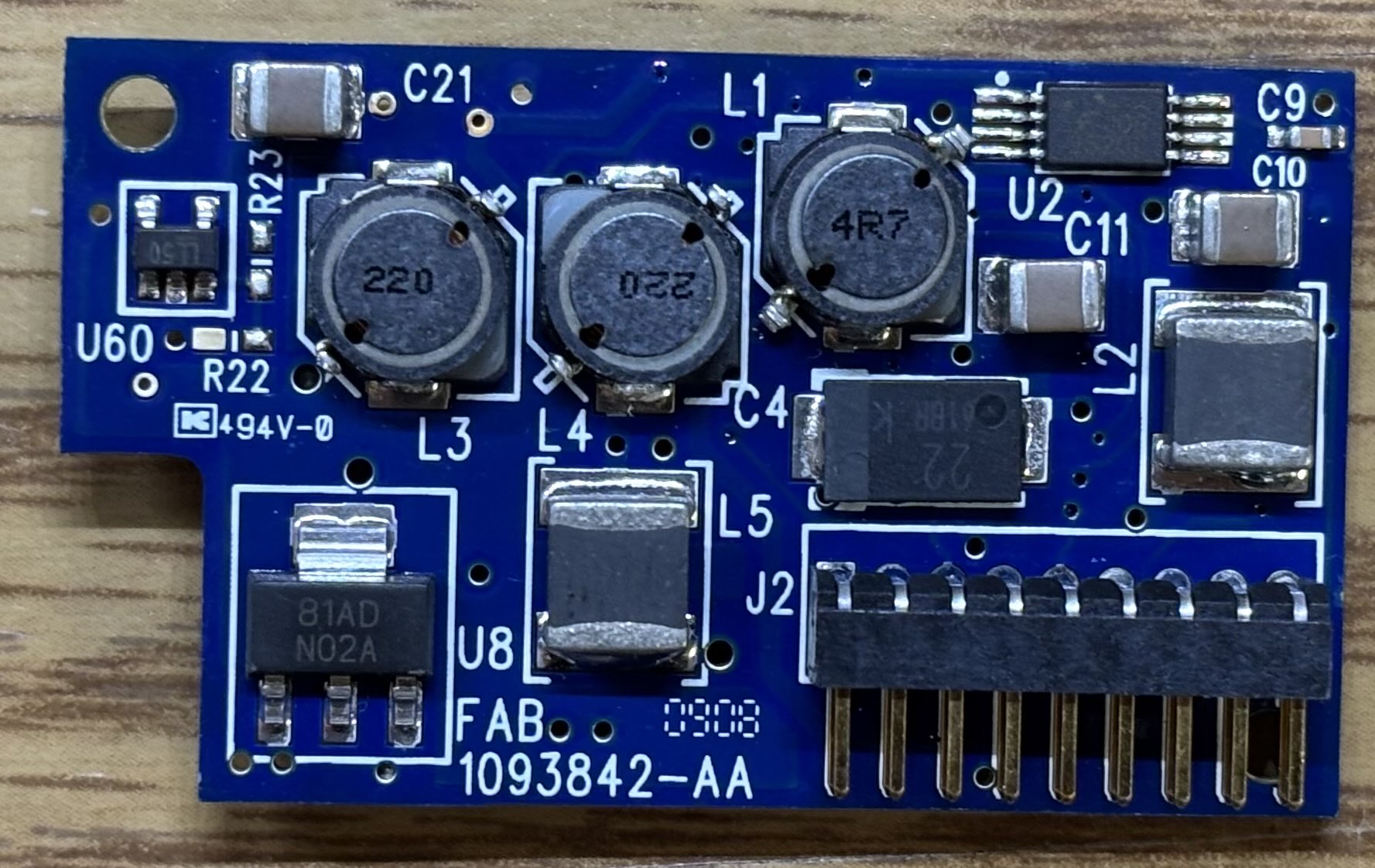
On the other side of the TE COOLER board are the components that actually do the "heavy lifting" and regulate power to the TEC. U2 is a Fairchild FDW2520C MOSFET. U60 is most likely a DC-DC converter or linear regulator. U8 is a LM337IMP linear regulator.
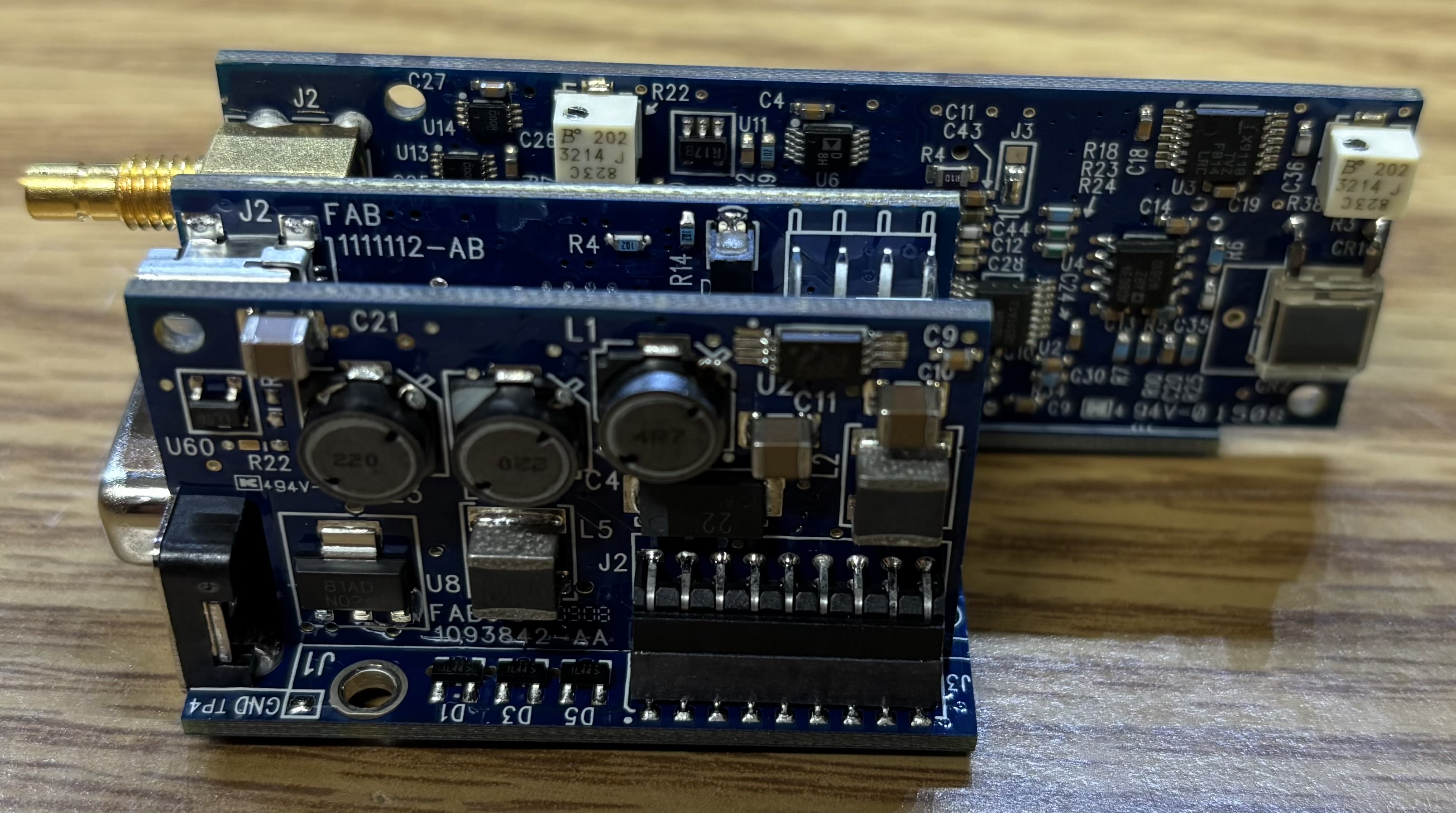
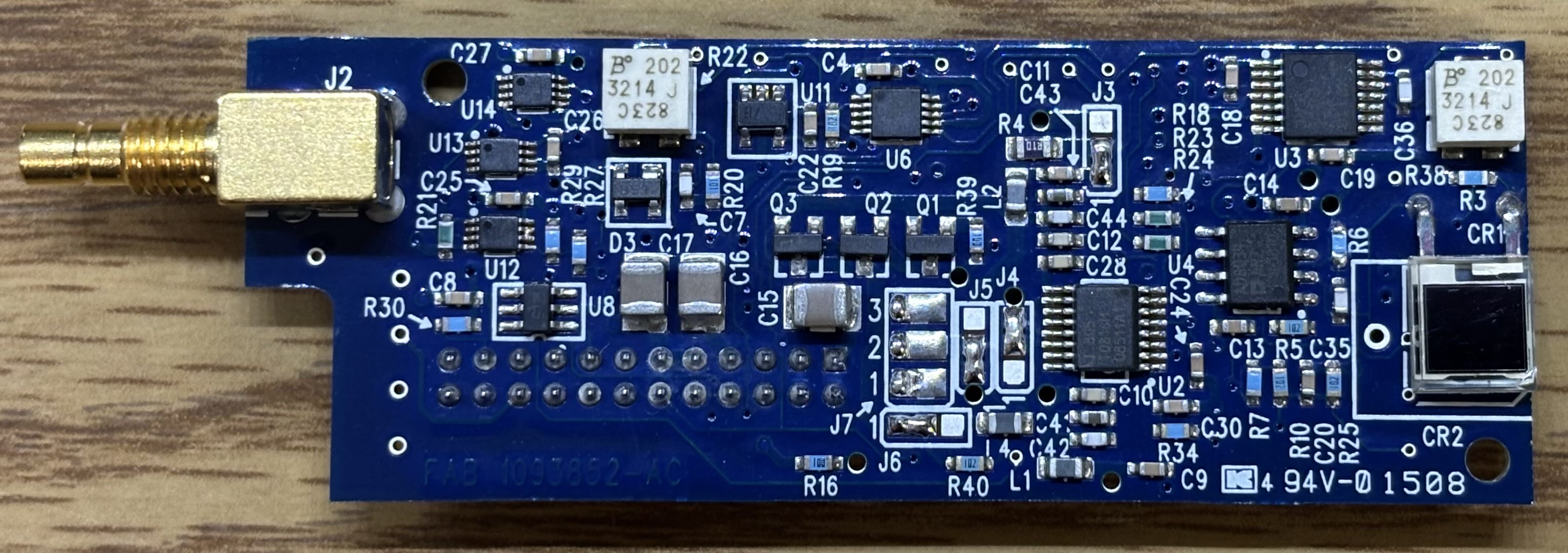
The star of the show is the COHERENT PEREGRINE II DIODE DRIVER (1093851). Quite an interesting name for an over-engineered but compact diode driver board. Based on our testing, SW1 appears to impact the photodiode gain as a sort of coarse adjustment. U5 and U10 are AD8034 operational amplifiers. U1 is an X9418WV24Z dual digital potentiometer. U15 is an AD5280 single digital potentiometer.
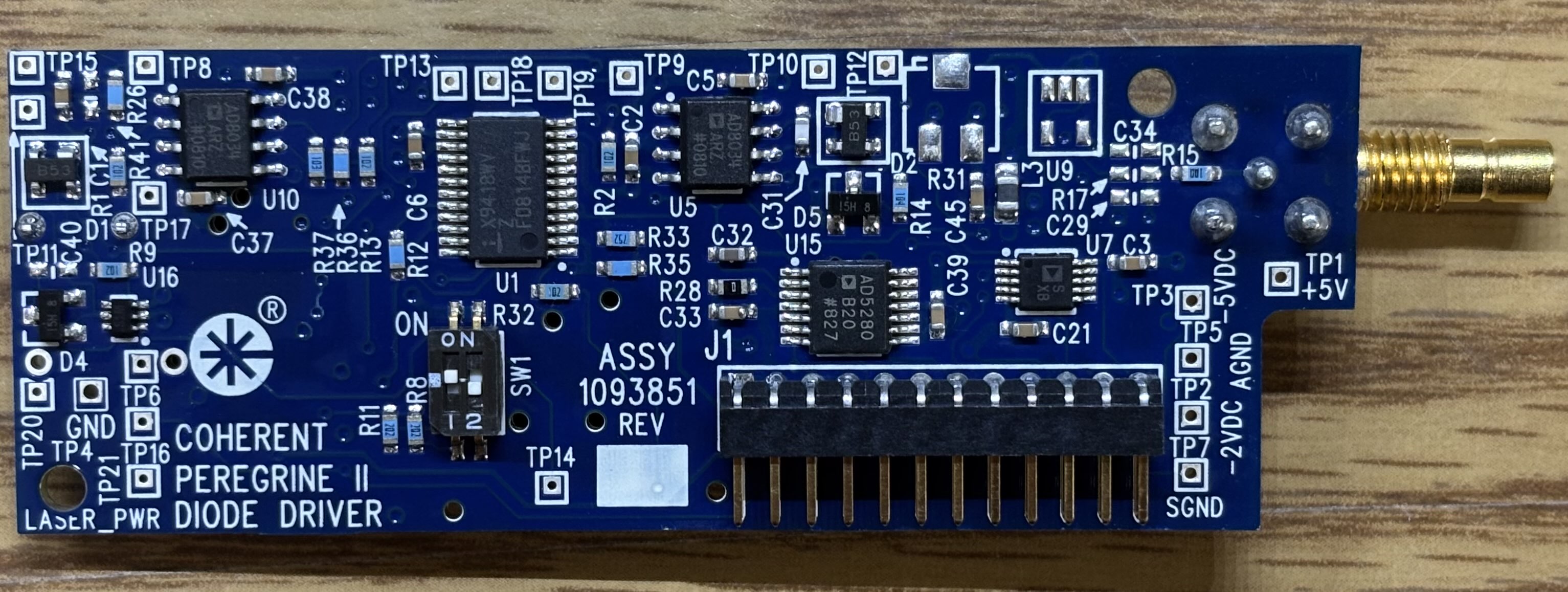
The laser diode is directly connected to solder pads 1, 2, and 3 of J7 via a flat-flex ribbon cable, which was removed from this board. CR2 is the monitoring photodiode which is used to monitor and regulate laser power depending on the current setpoint. A small portion of light is reflected off the anamorphic prism pair on to the photodiode. Therefor a scale or gain factor is used to obtain the actual laser output power. The gold SMB connector (J2) mounted to the rear of the board is the analog modulation input. R22 and R38 are potentiometers, but do not seem to impact diode current, we believe they are used for photodiode calibration. U3 is an X9118 digital potentiometer. U4 is an AD8034 operational amplifier. U2 is a T0816M dedicated laser driver IC. J3, J4, J5, and J6 appear to be solder jumpers that are used to set operating parameters for the diode driver. U12, U13, and U14 are all SN74LVC2G00 dual 2-input positive-NAND gates. U8 is a SN74LVC1G11 single 3-input positive-AND gate. U11 is most likely a CM7R153B linear voltage regulator. Q1, Q2, and Q3 are all LM431 adjustable precision zener shunt regulators.
A thorough analysis of the contents of the EEPROM chip revealed that there is one manufacturing command that can be used while not in manufacturing mode. The XDST= command with a value of 15-35 (e.g. XDST=15) will allow you to adjust the diode set temperature. This makes sense as that is a relatively reasonable parameter to change in the field. A full list of hidden manufacturing commands is provided below, along with the result of testing them is production mode.
| Command | Description | Test Result |
|---|---|---|
| EC= | EEPROM Configure | |
| ER= | EEPROM Read | |
| ES= | EEPROM Write | |
| HH= | Set Laser Hours | |
| WAVE= | Laser Wavelength | |
| XABIAS= | Diode Threshold Current | |
| XDST= | Diode Set Temperature | Works in normal production mode (value 15-35) |
| ?D2A | DAC Count | |
| ?A2D | A/D Count | |
| ?LPS | Cell Cal (Read) | |
| LPS= | Set Cell Cal | |
| ?LCSA & B | Current Cal (Read) | |
| LCSA & B= | Set Current Cal | |
| ?TH | Threshold (Read) | |
| TH= | Set Threshold |
Since we couldn't change anything else, we decided to try and program the EEPROM chip directly. This resulted in measured success. We changed the wavelength of a spare CUBE from 640nm to 532nm. The software reported this value fine. However, the system did go into a fatal error state and the fault code mentioned a checksum issue. It does appear that the system validates the checksum. This may be something we can overcome, as changing the XDST value and then examining the checksum could give us enough information to determine the algorithm. If successfully deciphered, we can use that information to regenerate the checksum after any change to the contents of the EEPROM.
Portions of the following section were generated using AI after analyzing the firmware. If something doesn't look right, please let us know.
Flash Memory Region 1: Calibration Header (0x000–0x027, 40 bytes)
| Offset | Hex | uint16 | Interpretation |
|---|---|---|---|
| 0x00 | 4F 61 | 20321 | Header integrity check (CRC or magic) |
| 0x02 | 0F FF | 4095 | DAC full scale (12-bit max = 0xFFF) |
| 0x04 | 0F E0 | 4064 | DAC practical upper limit (31 counts below max) |
| 0x06 | 00 00 | 0 | Reserved / zero |
| 0x08 | 03 20 | 800 | DAC operating point (diode current setpoint?) |
| 0x0A | 02 A5 | 677 | DAC/ADC calibration value (LCSA — Current Cal A?) |
| 0x0C | 01 90 | 400 | DAC/ADC calibration value (LCSB — Current Cal B?) |
| 0x0E | 00 69 | 105 | Diode threshold current in mA (XABIAS / TH) |
| 0x10 | 00 DC | 220 | Max operating current in mA |
| 0x12 | 00 0D | 13 | CDRH delay or config value |
| 0x14 | 64 EB | 25,835 | Lifetime hours counter (?HH) |
| 0x16 | 78 04 | 30724 | Config flags (as 2× uint8: 120, 4) |
| 0x18 | 02 80 | 640 | Wavelength (nm) |
| 0x1A | 00 28 | 40 | Rated power — NOMP (mW) |
| 0x1C | 00 28 | 40 | Max light constant power — MAXLP (mW) |
| 0x1E | 70 01 | 28673 | TEC / photodiode config (as 2× uint8: 112, 1) |
| 0x20 | 00 34 | 52 | Temperature setpoint (XDST — raw or ÷2 = 26°C) |
| 0x22 | BC 01 | 48129 | Cell Cal constant (LPS) |
| 0x24 | 93 28 | 37672 | Photodiode / current calibration constant |
| 0x26 | 8B | — | End of active data / transition byte |
Region 2: Serial / ID String (0x030–0x044)
Parsed as: Lot code (L9417510), variant (1), serial (1069417), wavelength (640) nm. The wavelength appearing in both the cal header and the ASCII string provides double confirmation.
Region 3: Firmware Help Text (0x080–0x43B, ~956 bytes)
The entire serial command reference is stored in flash as ASCII with CR/LF line endings. Three sections:
Control Commands (10 commands):
>= Prompt, ANA= Analog Current Mode, CAL= Calibrate Laser Power In Pulse, CW= CW or Pulse Mode, CDRH= Laser Delay, CLS Clear Text, E= Echo, EXT= External Laser Power Mode, L= Laser, P= Laser Power IN & OUT, T= TEC
Query Commands (24 commands):
?> Prompt status, ?ANA Analog Current Mode, ?BT Base Plate Temp, ?C Laser Diode Current, ?CDRH Laser Delay, ?CW CW or Pulse Mode, ?DT Diode Present Temp, ?E Echo, ?EXT External Laser Power Mode, ?F Fault Bits Decimal, ?FF Fault Bits Binary, ?FL Fault List, ?HH Hour Counter, ?HID Head ID Value, ?INT Interlock Status, ?LCK Interlock Status, ?L Laser, ?M Manual Auto Start, ?MAXLP Max Light Constant Pwr, ?MINLP Min Light Constant Pwr, ?NOMP Nominal Laser Pwr, ?PVPS Protocol, ?SP Get Set Power, ?STA Operating Status Number, ?SVPS Software, ?SV Software Version, ?T TEC, ?WAVE Laser Wavelength
Manufacturing Commands (11 commands):
EC= EEPROM configure, ER= EEPROM read, ES= EEPROM write, HH= Set laser hours, WAVE= Laser Wavelength, XABIAS= Diode Threshold Current, XDST= Diode Set Temp, ?D2A DAC Count, ?A2D A/D Count, ?LPS Cell Cal, LPS= Set Cell Cal, ?LCSA & B Current Cal, LSCA & B= Set Current Cal, ?TH Threshold, TH= Set Threshold
Note: The help text contains a typo — "Manfacturing" instead of "Manufacturing."
Region 4: Zero-fill (0x43C–0x6FF, 708 bytes)
Unused, zero-filled. May be reserved for future firmware expansion or additional string tables.
Region 5: Fault Code System (0x700–0x7DD)
Offset Table (0x700–0x70F): A 16-byte lookup table where each byte is the offset into the string table for the corresponding fault code. The firmware reads ?F fault bits as a bitmask, then indexes into this table to retrieve the human-readable error string.
Fault Strings (0x710–0x7DD): Null-terminated ASCII strings:
| Fault Bit | Offset | Message |
|---|---|---|
| 0 | 10 | Bad Command |
| 1 | 22 | Bad Data |
| 2 | 31 | EEPROM ChkSum |
| 3 | 45 | System OK |
| 4 | 55 | Diode Temp |
| 5 | 66 | External Interlock |
| 6 | 85 | I2C |
| 7 | 89 | Value Out Of range |
| 8–10 | 108–110 | (null/reserved — 3 bytes of 0x00) |
| 11 | 111 | Reset Flash |
| 12 | 123 | Reset Clock |
| 13 | 135 | Comm Tx Timeout |
| 14 | 151 | Comm Rx Overflow |
| 15 | 168 | Fatal Error |
Fault bits 8–10 point to null bytes, suggesting three reserved or unused fault conditions.
Region 6: Tail Mirror Block (0x7DE–0x7E7, 10 bytes)
| Offset | Hex | Mirrors | Value |
|---|---|---|---|
| 0x7DE | B7 B8 | — | Integrity check (CRC-16 of mirrored fields?) |
| 0x7E0 | 00 12 | — | Offset pointer or region length (18 = 0x12) |
| 0x7E2 | 4F 61 | Header 0x00 | Header magic (20321) |
| 0x7E4 | 00 0D | Header 0x12 | Value 13 (CDRH delay?) |
| 0x7E6 | 64 EB | Header 0x14 | Hours counter (25,835) |
This could be a firmware resilience mechanism that allows the system to detect and recover from a corrupted header.
Open Questions
1. Header magic (0x4F61): None of the standard CRC algorithms produced this value from the calibration data. It may use a proprietary polynomial, or it could be a simple identifier/version tag rather than a computed checksum.
2. Fields 0x16, 0x1E: These don't decode cleanly as uint16. They may be paired uint8 values (120/4 and 112/1 respectively), possibly representing max current limits and protocol/mode flags.
3. Cell Cal and Current Cal constants (0x22, 0x24): These large values (48129, 37672) are likely factory-measured calibration slopes or offsets for the photodiode cell and current sensor, but the scaling formula is unknown without firmware analysis.