Overview
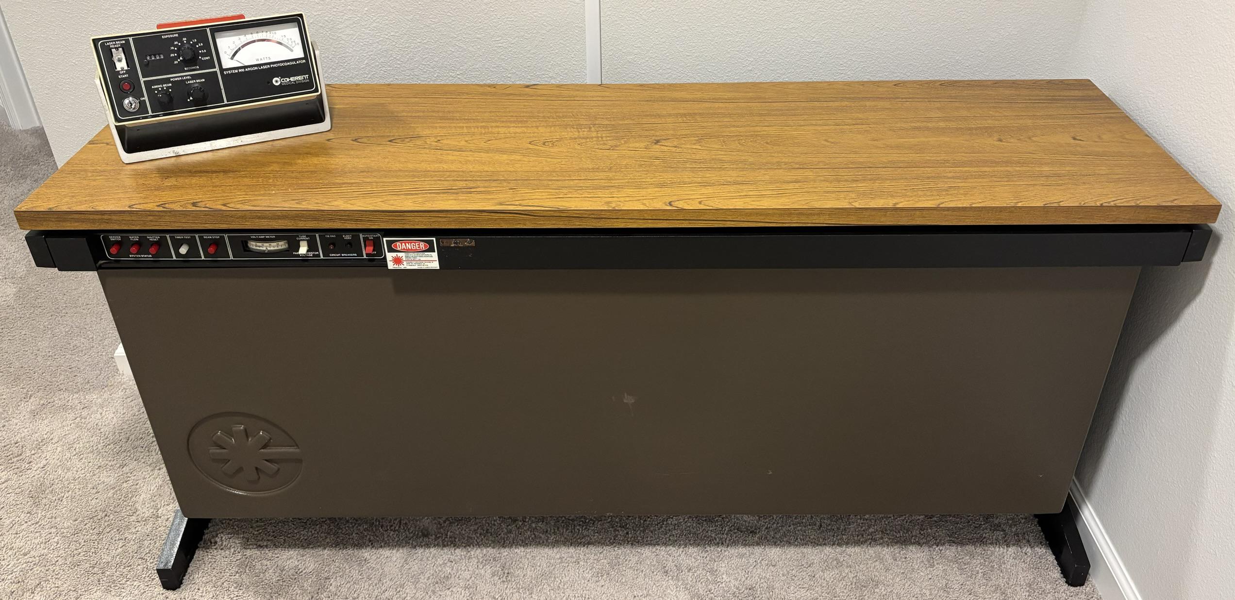
The Model 900 (900Z in our case) is an enormous laser system developed and manufactured by Coherent Medical in the 70s and 80s for the purpose of laser photocoagulation. Our unit was manufactured in 1982. Photocoagulation dates all the way back to the 1940s and 50s and is used to treat a variety of diseases of the eye. It's a complex process that continues to evolve, but essentially a beam of laser light is used to cauterize ocular blood vessels. This can help slow down degradation but is unlikely to undo damage that has already been done. Diabetic retinopathy is an example of a medical condition that may be treated with laser photocoagulation. The System 900 is a self-contained argon laser, power supply, and control system confined within a cabinet that resembles a small desk. It requires a 3-phase, 208 V AC power input and features a water-cooled argon laser tube. Water cooling and chiller equipment must be connected externally, as there are no pumps or chillers contained within the System 900. We often refer to the System 900 as the "desk laser" as it really just looks like a small desk. It has a nice wood top, solid metal frame, and some stylish plastic side panels with an embossed Coherent logo. Don't be fooled, despite it looking like a small desk, the system weighs nearly 500lbs when all components are installed. The individual we obtained this system from attempted to load the system into the back of a Toyota Tacoma, causing the rear to sag significantly. We decided it would be best (and safest) to disassemble the system into pieces for loading and transport.
Enclosure and Frame
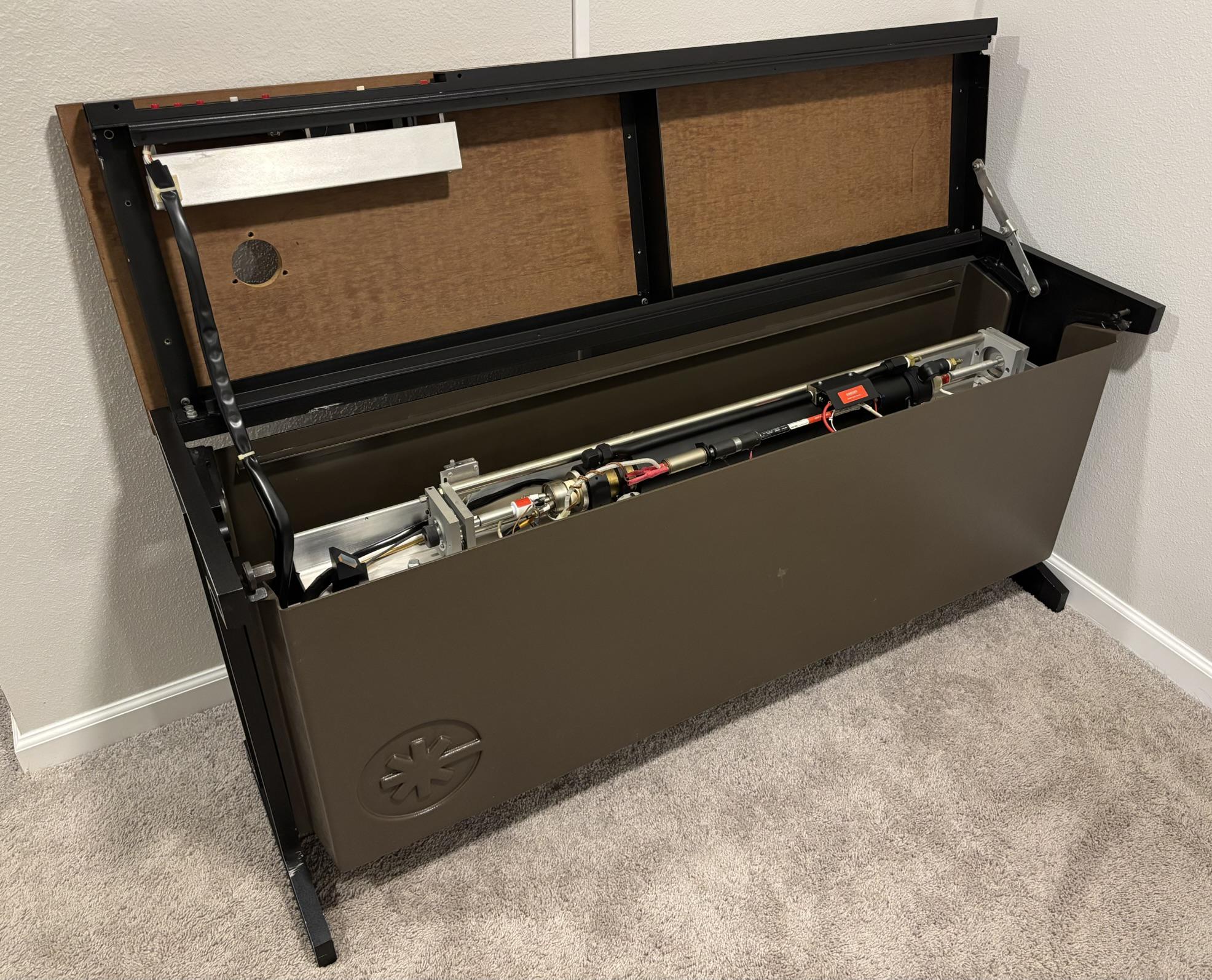
The top section of the metal frame hinges up and is held in the open position by a folding metal strap. This allows easy access to the laser tube and components that reside in the top section. It's worth noting that there are two large nuts on either side right below the wood top that can be tightened to secure the top section in the closed position. These can be loosened with a hex key to allow the top to be opened.
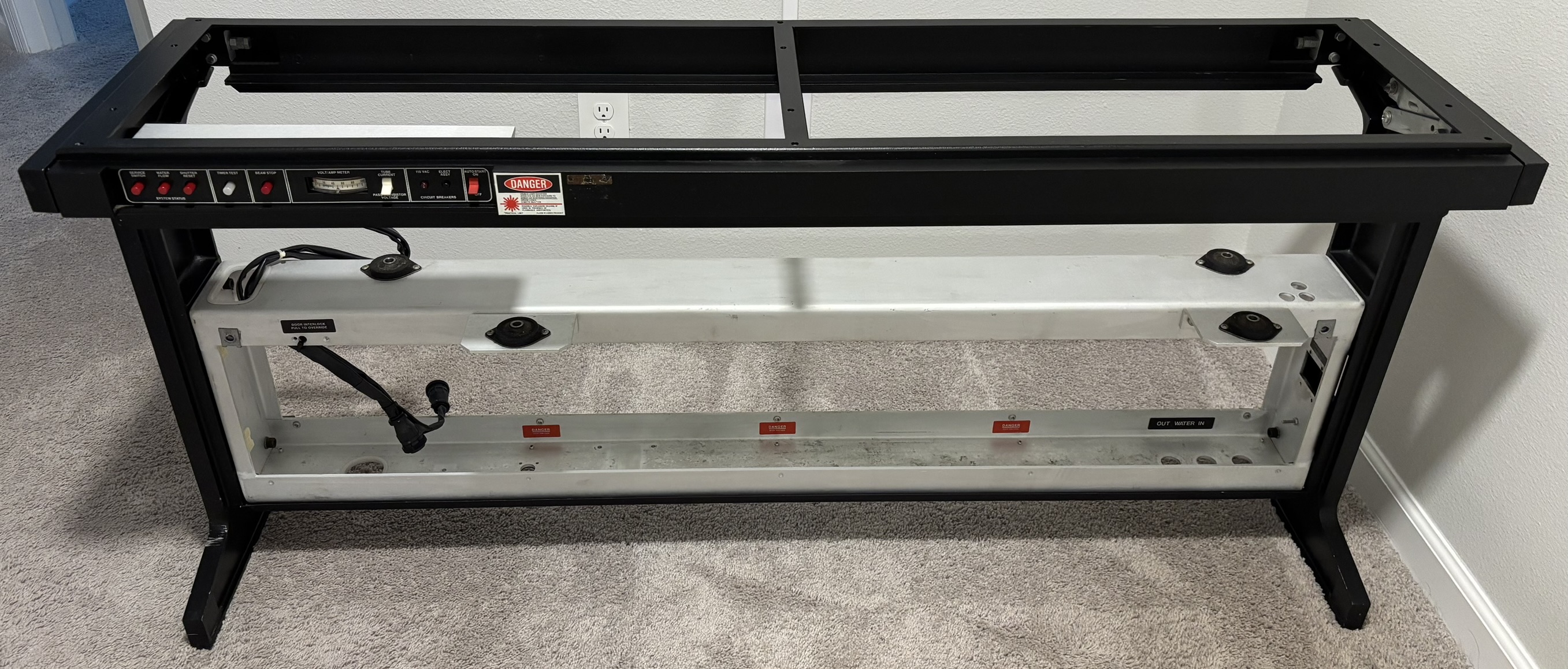
Below is an image of the aluminum frame, with nearly all components and covers removed, including the wooden top. It is of exceptional build quality, much like an old sewing machine table. The middle aluminum section is secured to both sides of the frame and keeps the assembly together. The laser tube assembly is secured to the four rubber vibration-isolation boots by some long bolts. In a completely assembled system, the power supply components would be contained within the center aluminum enclosure. This would be accompanied by two aluminum trays that mount on either side of the middle section and contain additional power supply and control components.
Laser Tube Assembly
Laser power is produced by a Coherent model I-90-MA water-cooled argon tube. This tube is similar to the Coherent Innova 90 and is likely a variant of the 90 series. A member of Photonlexicon forums described the tube as a "stretched I90, aka I90MRA or I90MK". The Innova 90 systems appear to use a much smaller power supply compared to the System 900, likely due to the System 900's larger tube size and output power. The warning sticker on the desk frame reports a maximum output power of 9 watts, however the actual output power would likely have been a bit lower (around 5-7 watts). The argon tube is secured within two end plates and 3 stabilizer bars. There are adjustment screws on both ends to position the end reflectors. The whole tube assembly is mounted to a very heavy piece of milled aluminum.
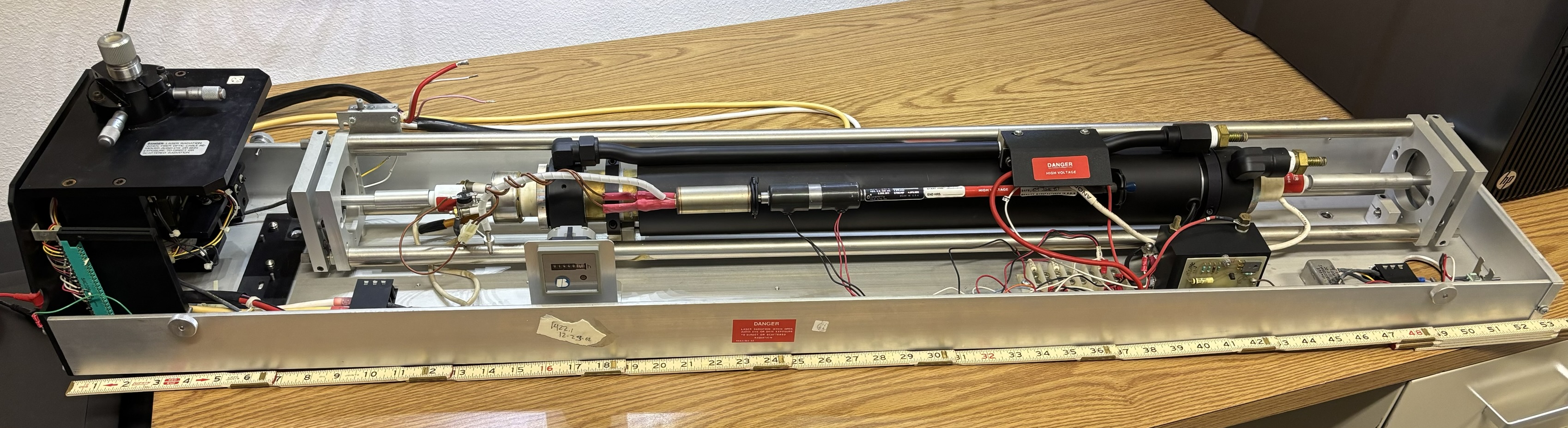
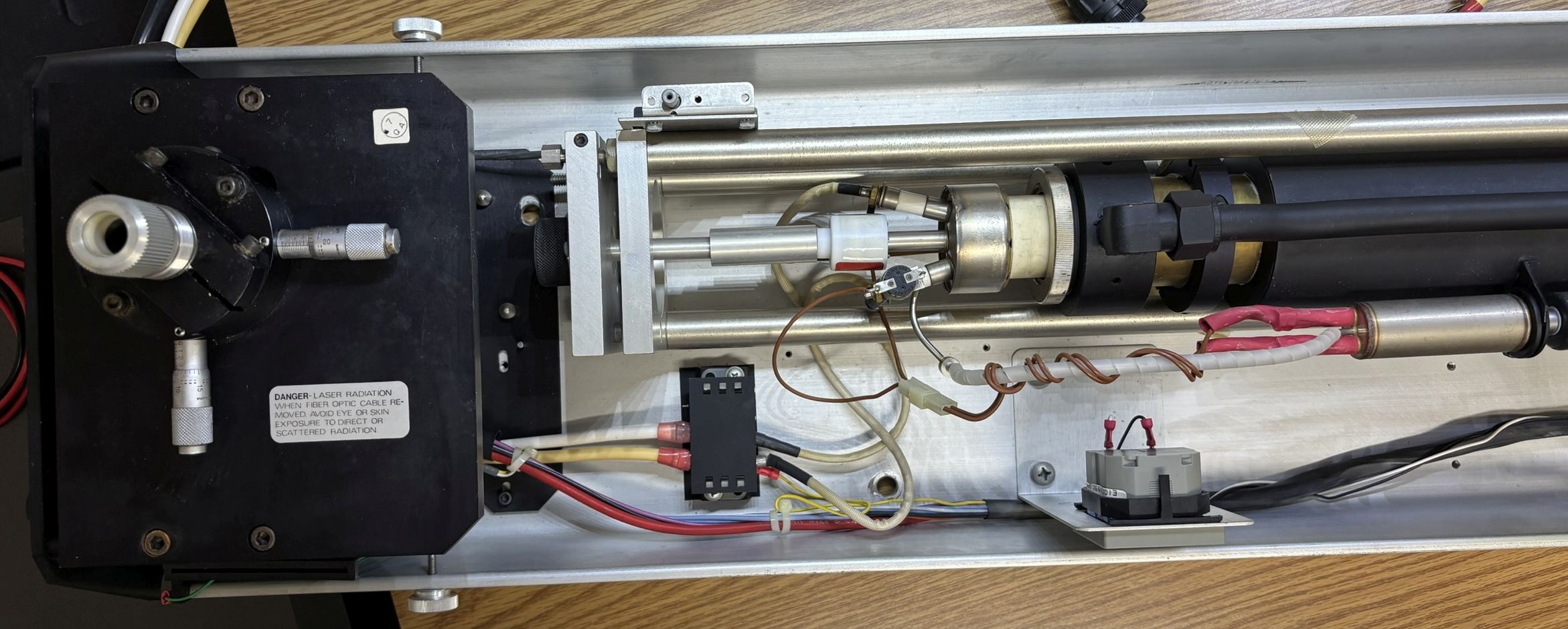
Focusing on the left section of the laser head assembly, there is a kinematic fiber coupling mount located on a black anodized aluminum plate, which has some micrometer adjustment screws. Below the output aperture are some beam filtering and manipulation optics, that are actuated by solenoids and motors. The shutter is also located below. An interlock switch is mounted to the side of the tube carrier frame and can be overridden by pulling out the gray button that is normally depressed when the cover is installed over the laser head section. This is the cathode side of the tube. The cathode end connections are visible along with a thermal cutout switch. The hour counter is installed in a small right-angle bracket mounted to the aluminum channel.
The middle section reveals an interesting feature of this laser tube. The small section of tube covered in three individual labels connects to the main plasma tube, but is cut off by two solenoids. The solenoids are located more towards the left and each have two wires leading to the terminal block on the bottom aluminum channel. The purpose of this feature is to add argon gas to the laser tube when needed. Throughout the laser's life, it may consume gas and require replenishment to continue performing as intended. Normally, re-gassing a laser is a complex and laborious process, and often signaled the end of the line for an otherwise functional laser system. This feature allows argon gas to be added to the laser tube either automatically by a controller, or manually with a switch. This extends the life span by minimizing the need for a complex re-gassing procedure. The small tube mentioned earlier is a high-pressure reservoir of argon gas, which is at a much higher pressure than the rest of the tube. To perform a fill, the first solenoid would be activated briefly, which allows a small amount of gas to exit from the high-pressure chamber and into the space between the two solenoids. After this, the first solenoid would be de-energized and closed to cut off the high-pressure chamber. Next, the second solenoid would be energized to open it, allowing the small amount of high-pressure argon gas to enter the main laser tube. The second solenoid could now be de-energized. This fill process could have been repeated several times as needed or completed automatically by an auto-fill controller equipped on some systems. It is important to note that both solenoids should never be activated at the same time. This would cause all the high-pressure gas from the small chamber to be immediately dumped into the main tube, which could destroy it.
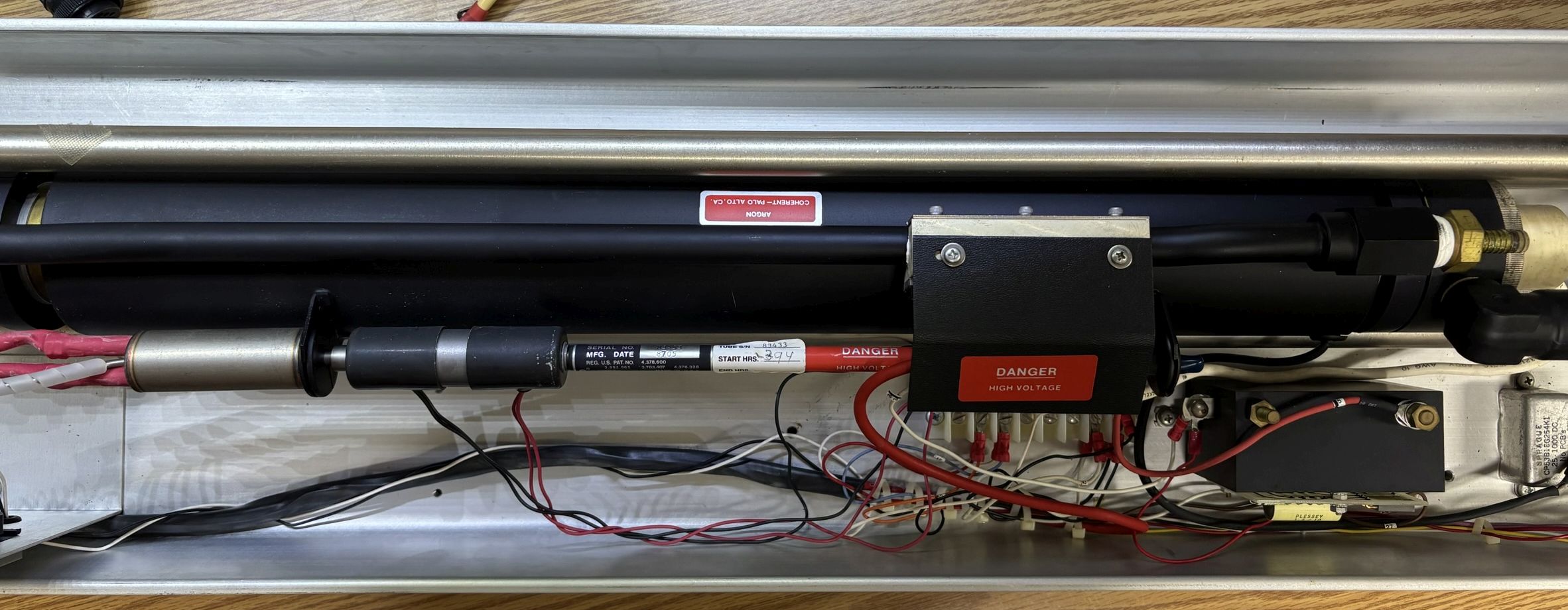
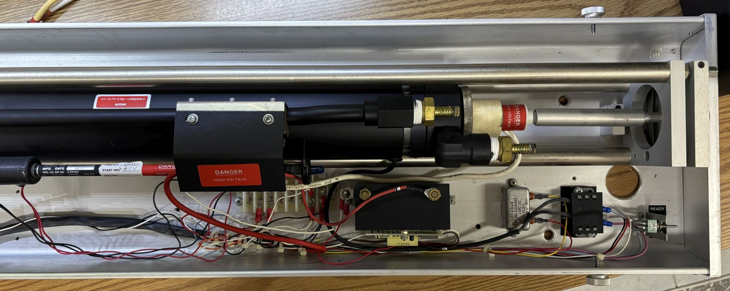
The right side of the tube is the anode side. Under the plastic cover with the high voltage sticker is a large diode in series with the anode connection. There is also a high-voltage step up transformer and related circuitry which is likely used to strike the tube during startup. The water cooling hoses would have connected to the brass hose barb fittings on the side of the tube. All the way on the right is the toggle switch for manually filling the tube with gas. It's a 3-position momentary toggle. Moving it to the up "READY" position activates the first solenoid. Moving it to the down "FILL" position activates the second solenoid, adding argon gas to the laser tube.
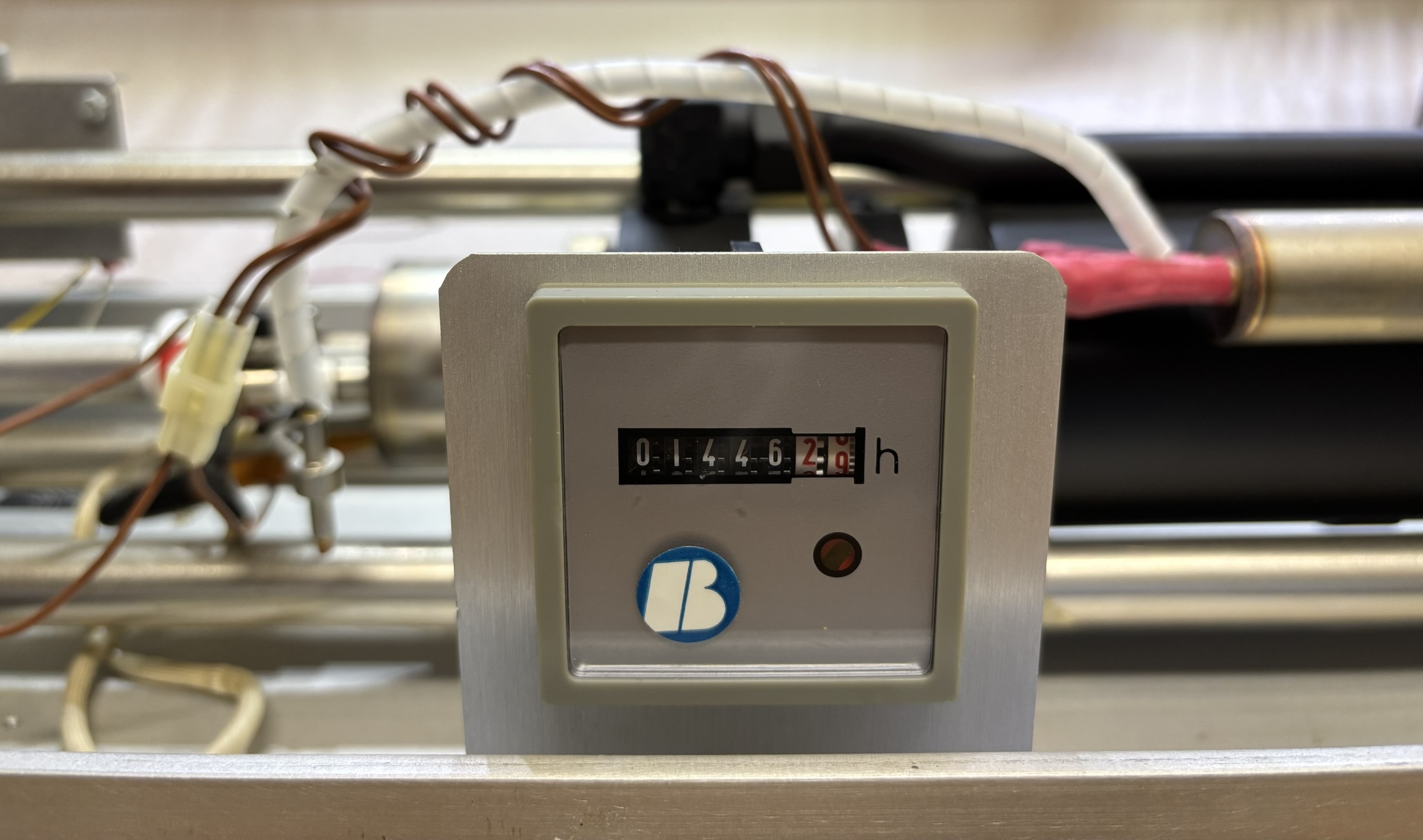
The electro-mechanical hour counter indicates 1,446 hours on the tube.
Power Supply
The power supply section is enclosed by two hinged metal trays mounted to the middle (interior) of the frame. It's a monster that requires 3-phase 208 V AC power. According to the sticker on the side by the circuit breaker, the system requires 35 amps of input current. This equals a theoretical maximum power draw of 14,000 watts! That was likely only during startup or running the laser near its max, it probably did not require that amount of power during all phases of operation. That really speaks to the insanely inefficient nature of argon gas lasers, all of that power for just ~5 watts of laser power!
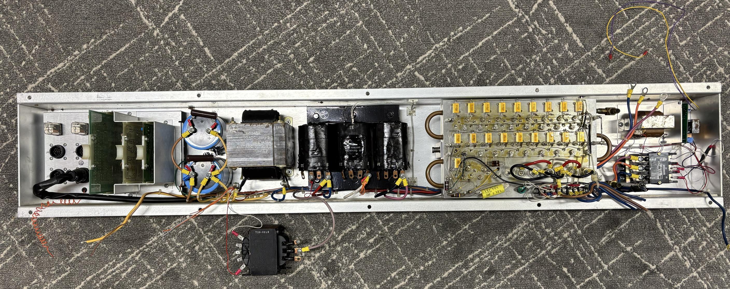
The power supply tray has a number of components which are listed below, along with descriptions. Components are listed in order from left to right of the tray.
- Twist-lock connector and relay panel
- Control cards cage
- Two large Mallory CGS series capacitors
- Power transformer
- Large 3-phase power transformer
- Passbank module
- Fuse block (mounted below passbank module)
- Main power contactor
- Control power transformer
- Fluid flow switch control board (mounted on right-angle bracket)
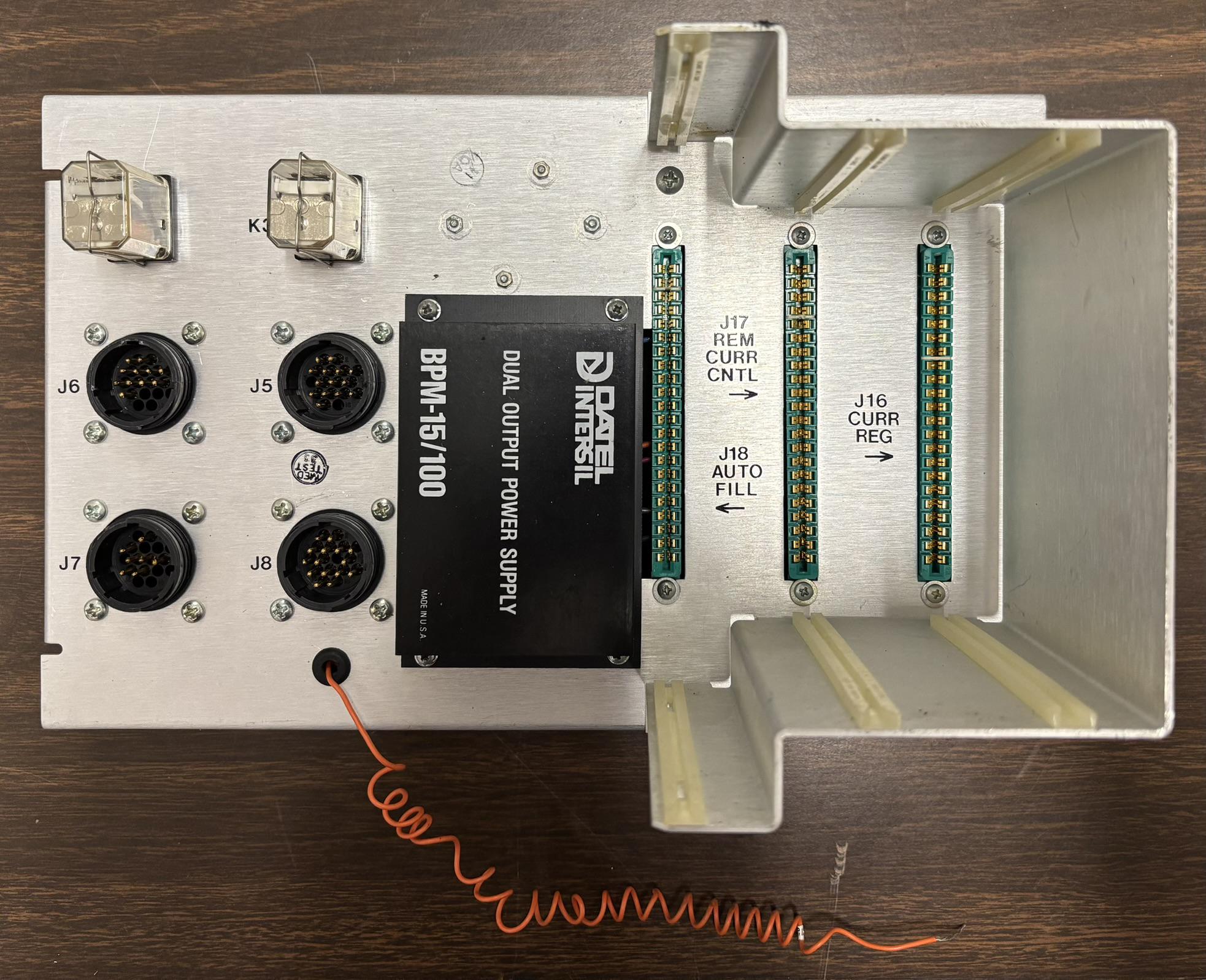
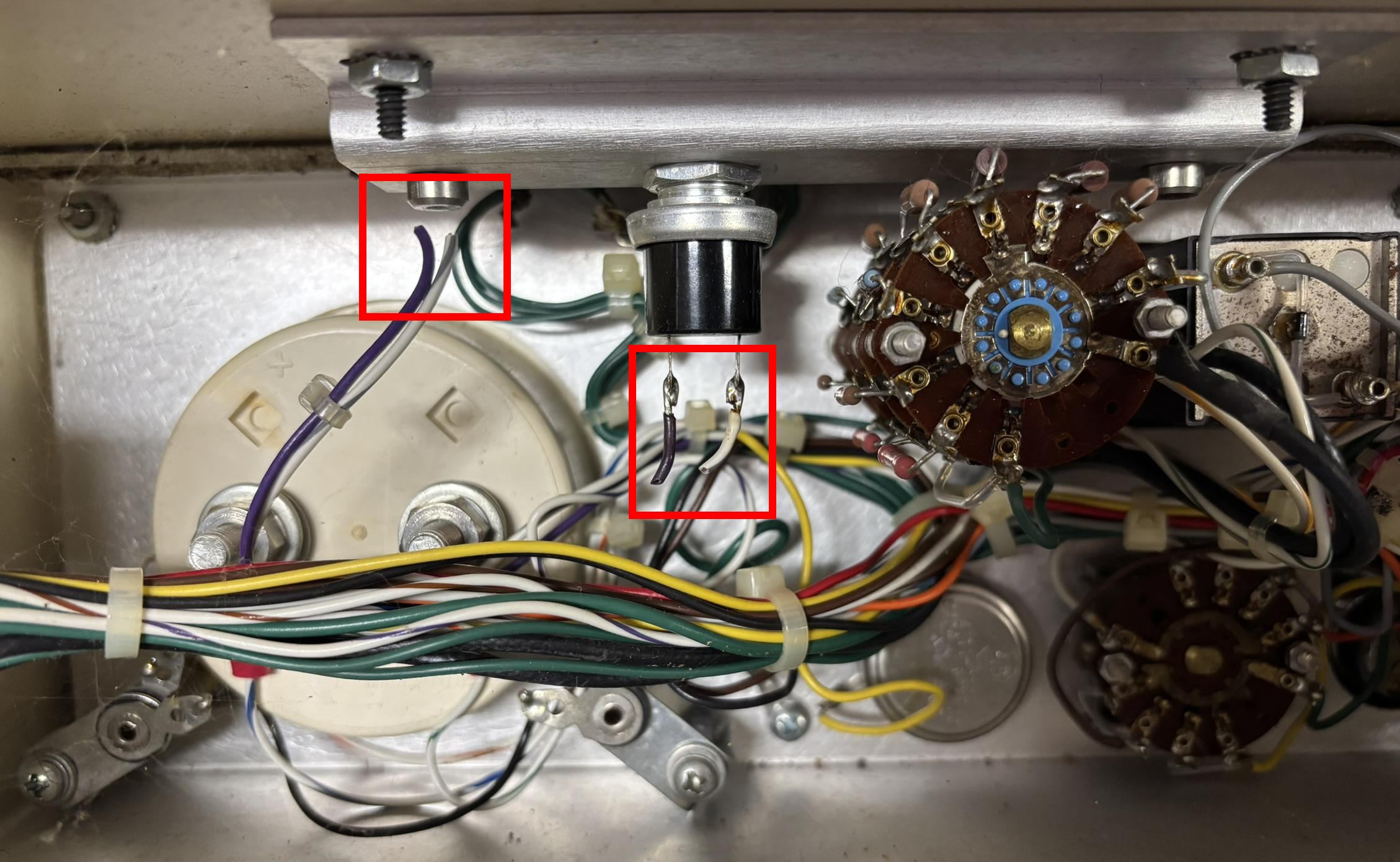
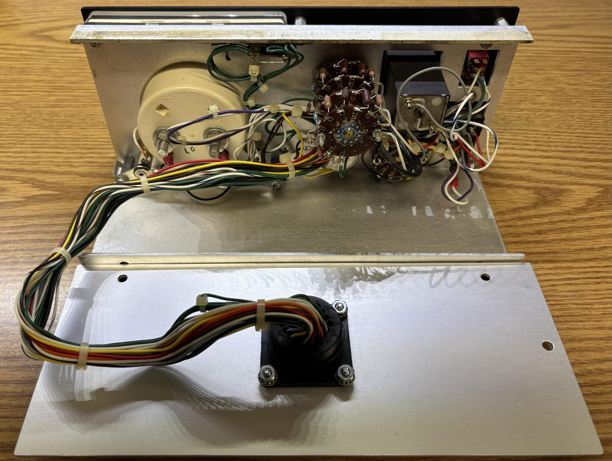
This is the control and connection section of the power supply. It is a separate aluminum panel that mounts to the main power supply tray. There are 4 twist-lock connectors for connections to other components of the power supply. There is a self-contained dual output power supply manufactured by DATEL INTERSIL. There are 3 card edge connectors to which the auto fill, remote current control, and current regulation cards insert into.
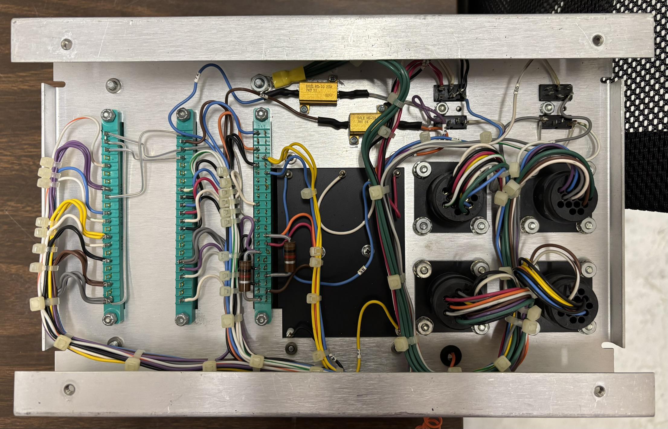
The reverse side of this panel contains a couple of resistors along with all of the connections between the twist-lock connectors, control cards, and dual output power supply. The individual control cards will be covered in the control system section of this writeup.
This is the pass transistor array or "passbank". It consists of several transistors, diodes, and resistors mounted to a water cooled aluminum frame. There is a section of pipe pressed into the aluminum that is part of the water cooling loop. The laser tube and passbank are the only water cooled components and are in series with each other. The resistors are 20-watt units manufactured by DALE. They are wired in parallel with the transistors. There are also 6 stud-mounted diodes.
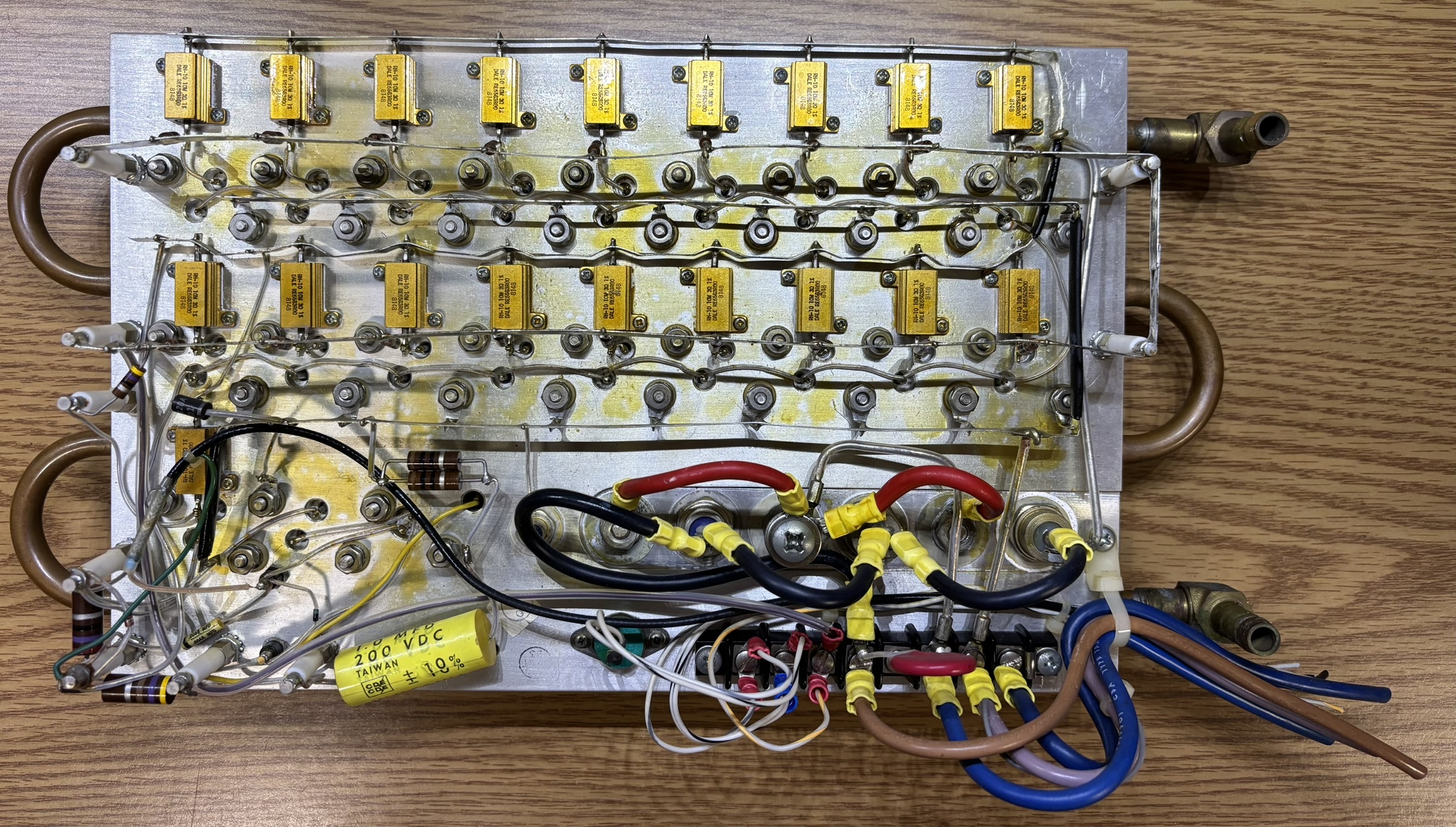
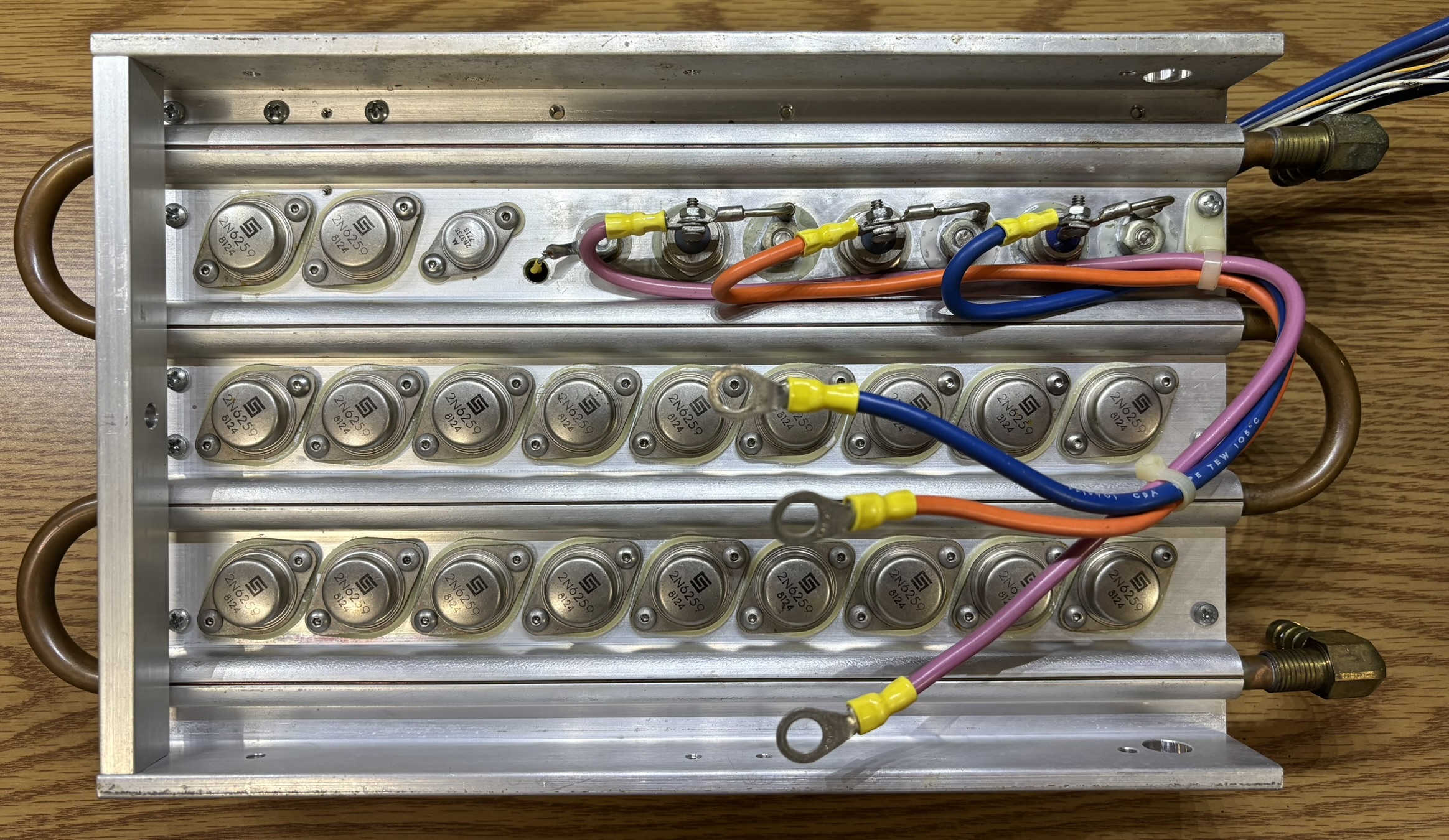
Here is the rear side of the passbank, where you can see the individual 2N6259 transistor packages and the water cooling lines pressed into the aluminum frame. The whole passbank module is secured to a power supply side cover by spring-pins for easy access and removal.
Control System
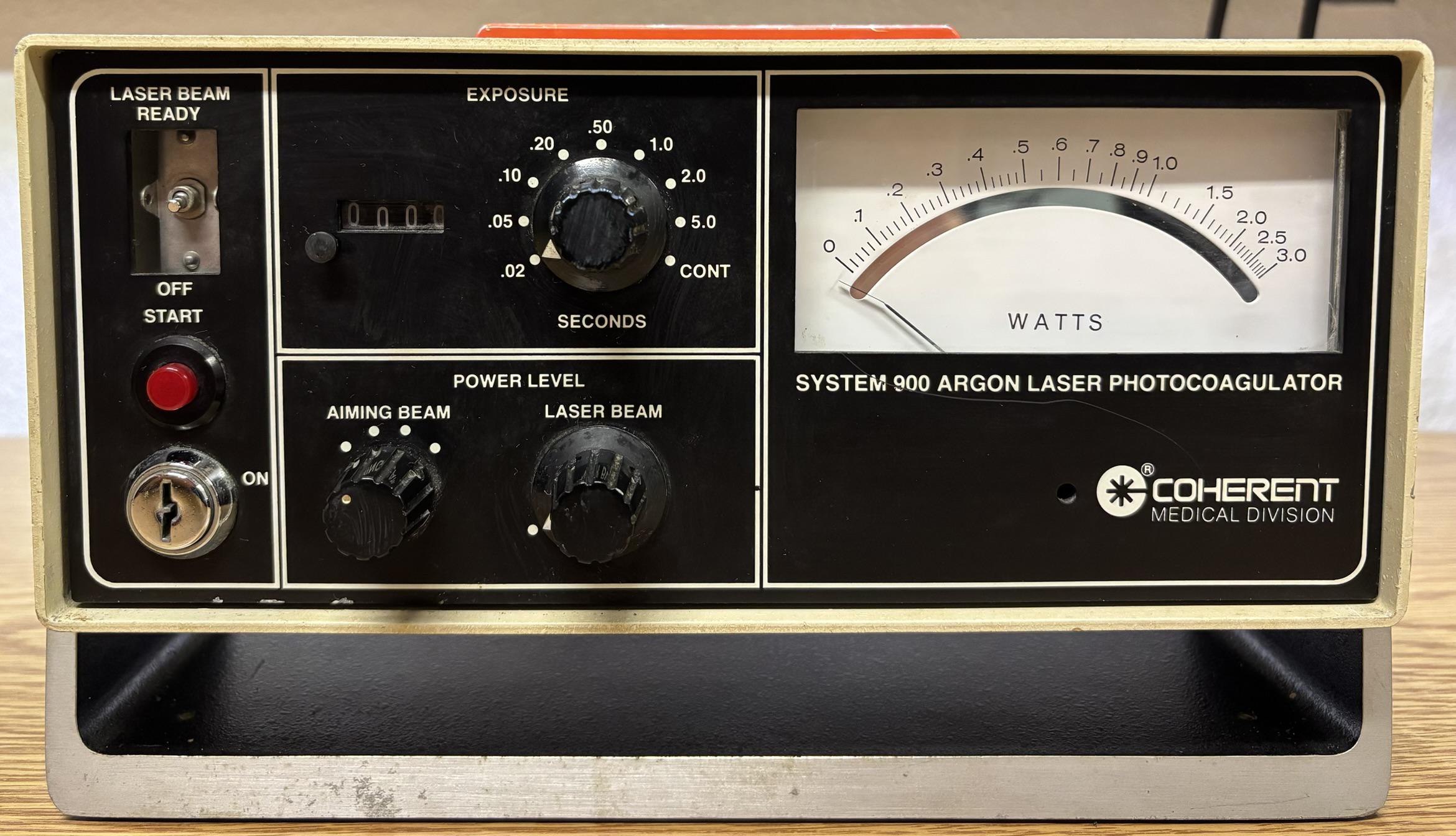
The primary controller is a small box that is connected to the system via a single cable, but not attached to the frame so it can be repositioned easily. The controller enclosure is made of aluminum and features a metal swivel base that nicely matches the aesthetic of the system's frame. The controller is relatively basic and includes the following features: interlock keyswitch, start button, beam ready/off switch, exposure time selector and counter, aiming beam selector, laser beam power adjustment, and an output power meter.
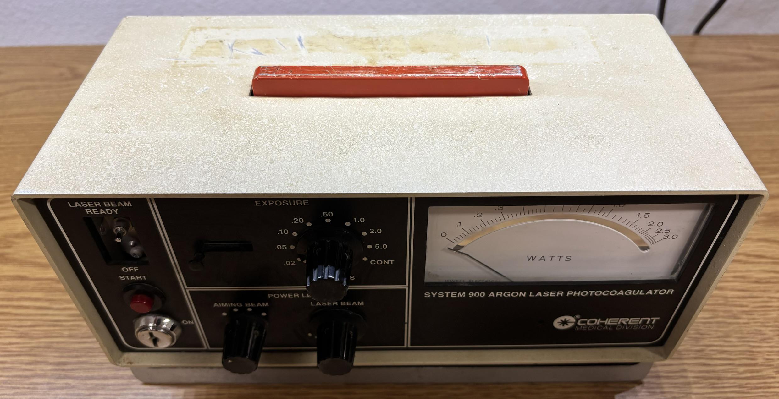
On the top of the controller is a large rectangular button that we can only presume is an emergency stop. It is wired in series with the keyswitch and is normally closed. The laser beam is actually activated via a foot-switch, so it's definitely not used for that either.
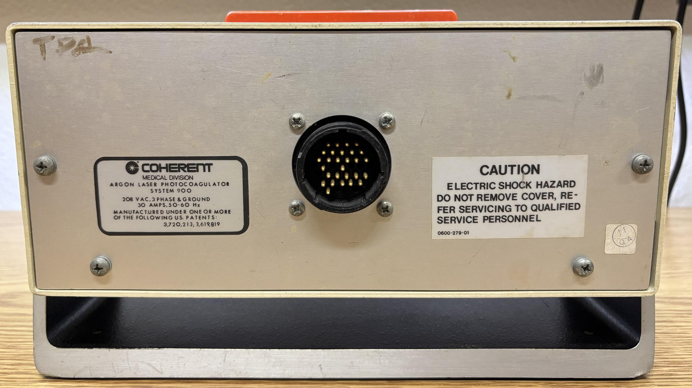
On the back of the controller is the typical twist-lock, multipin connector commonly found on older gas lasers, accompanied by the obligatory warning and information labels.
When we first opened up the controller, we immediately noticed something odd. The supposed emergency stop switch had its wires cleanly cut! The lack of any wire coverings combined with the excess length left on the switch lead us to believe this was definitely a deliberate action. This action would disable the laser completely, as the interlock circuit could never be closed. Perhaps this was done on purpose to "decommission" the system, or maybe while haphazardly opening up the controller? We'll never know! We reconnected the wires later on to restore the controller to a fully functional state.
Taking a look in the controller reveals a simple design with no active circuitry. The rotary selector for exposure time appears to engage different resistor values. The rest of the switches and selectors are nothing complex and just connect to the control system components in the power supply area. The meter is backlit by two incandescent bulbs mounted from the inside.
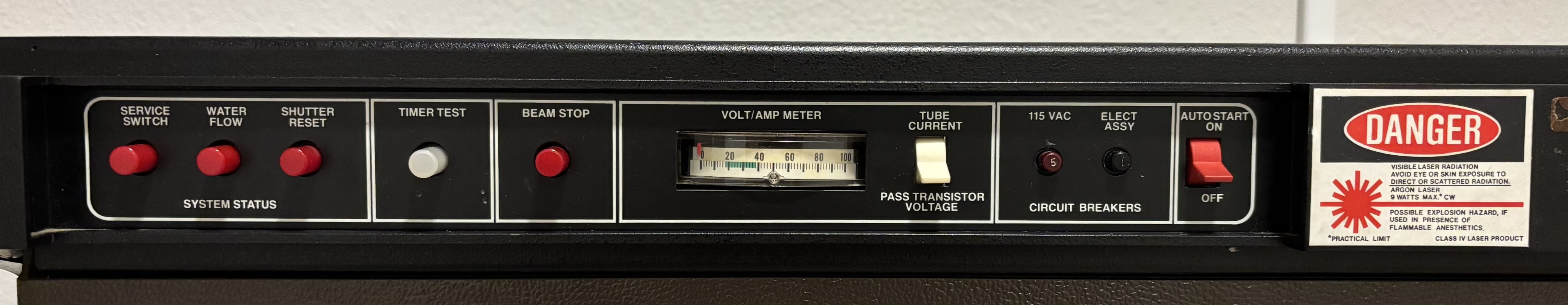
On the front of the frame and below the wooden top is a small bank of switches and indicators that allow for some basic control and monitoring of the system.
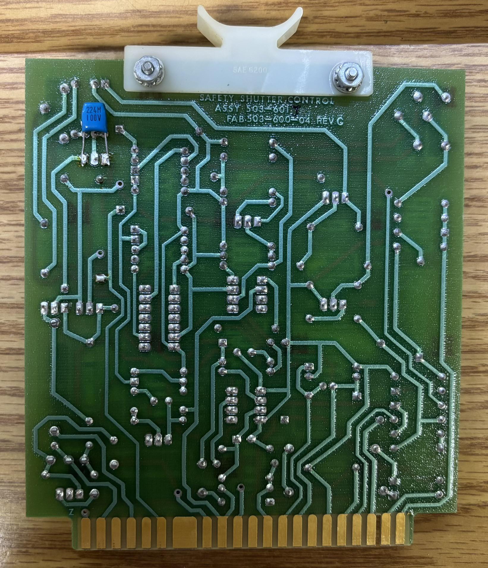
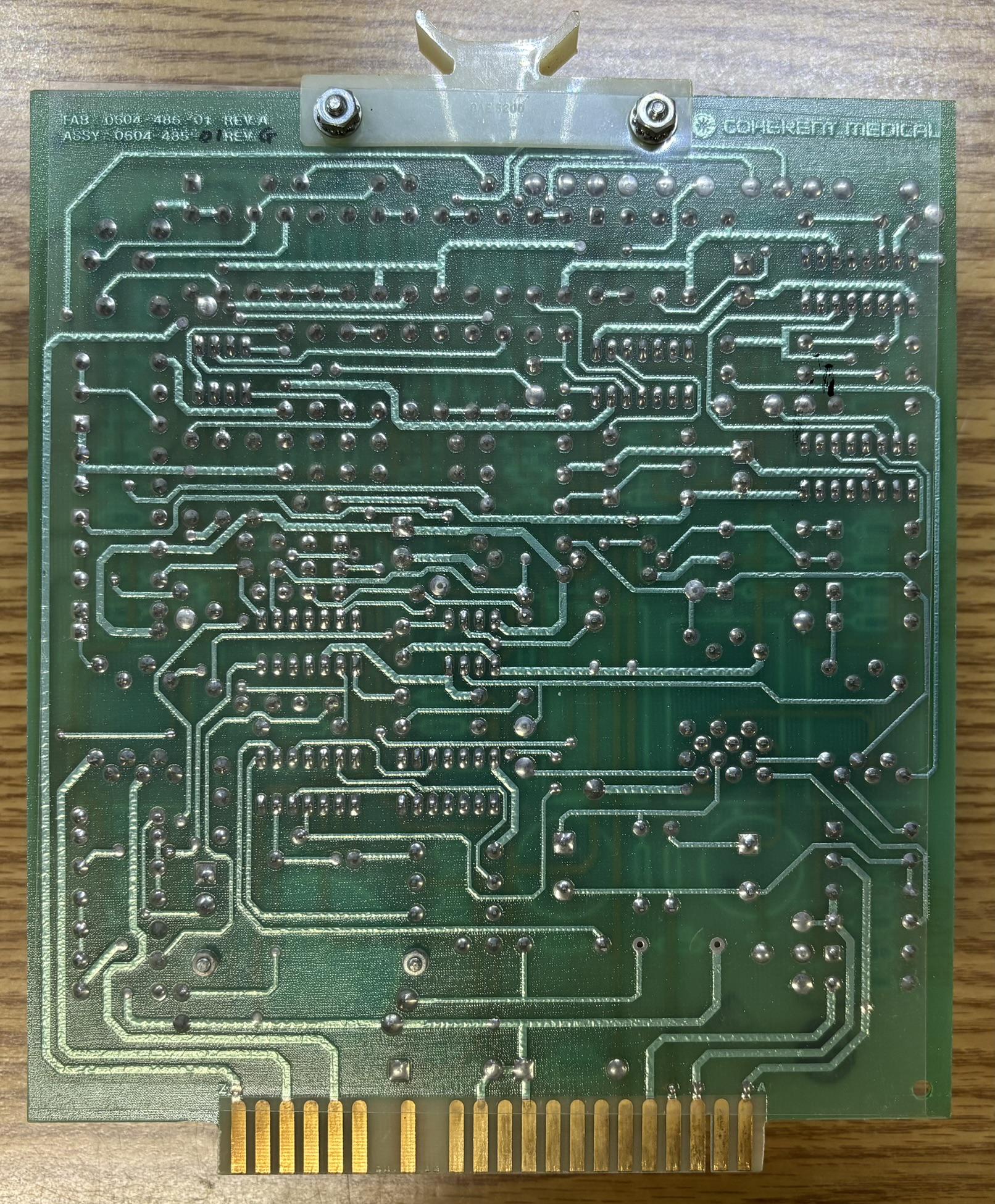
This it the safety shutter control card that plugs into the J14 edge connector.
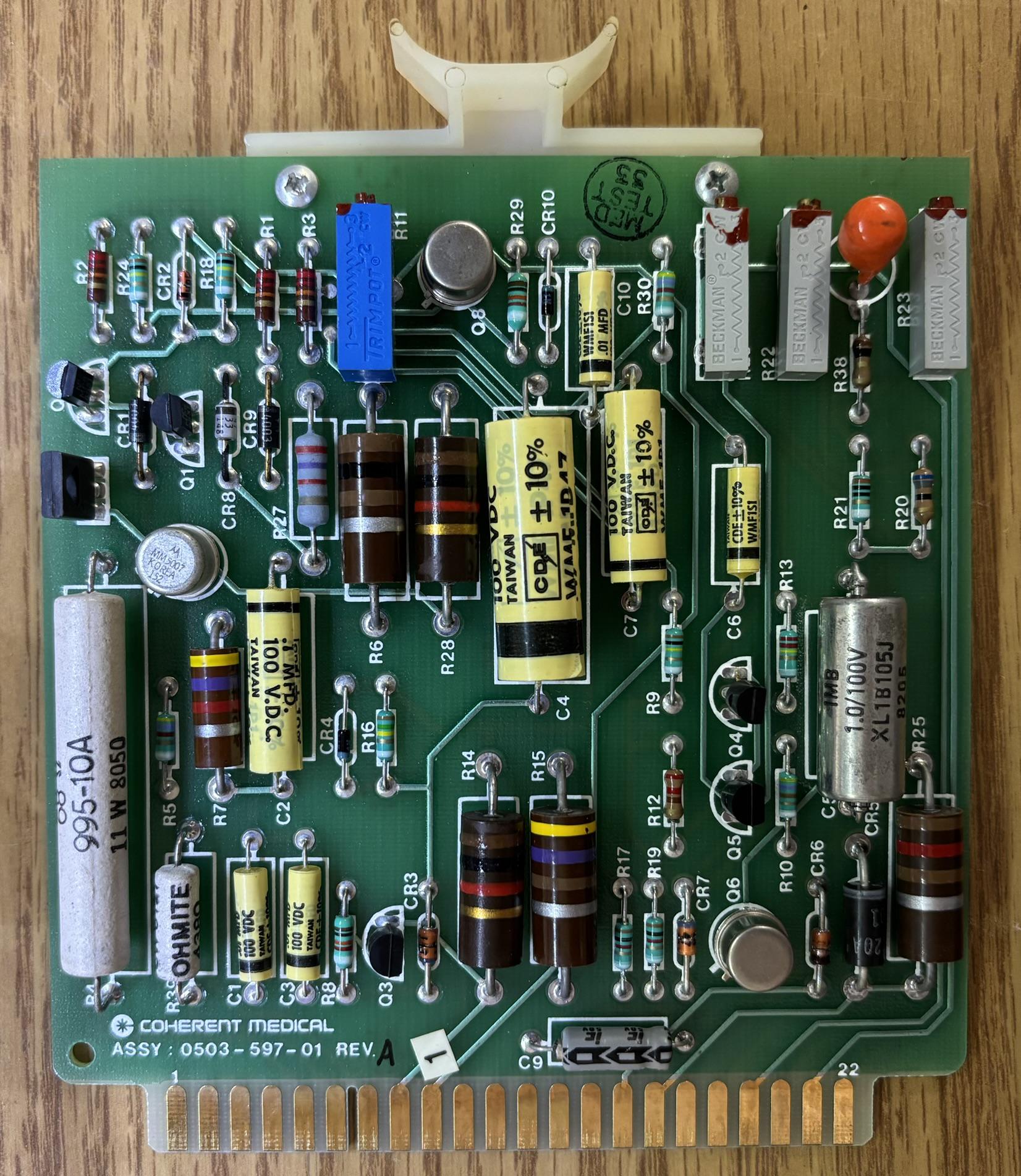
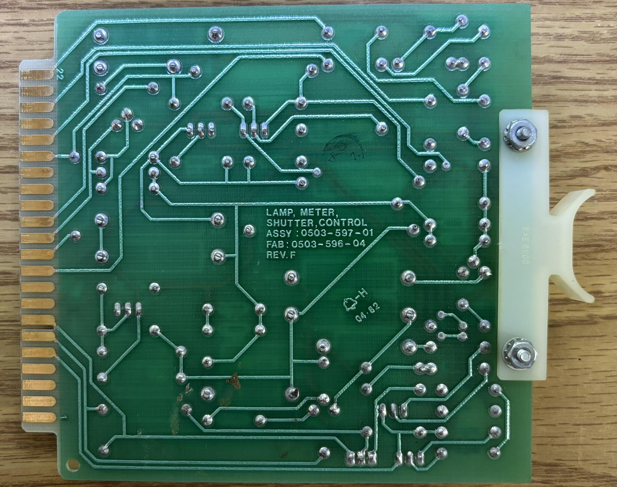
This is the lamp, meter, and shutter control card that plugs into the J15 edge connector.
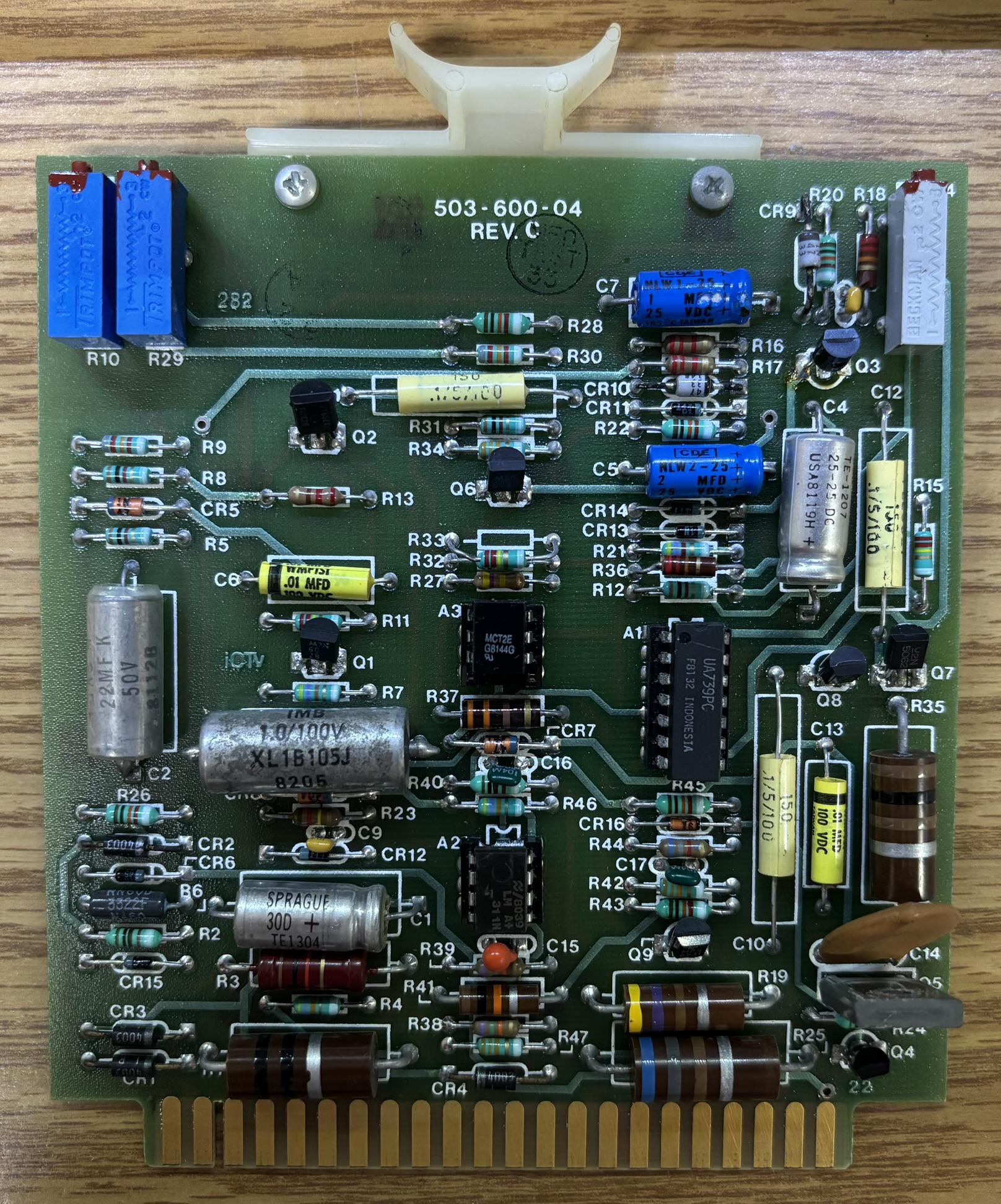
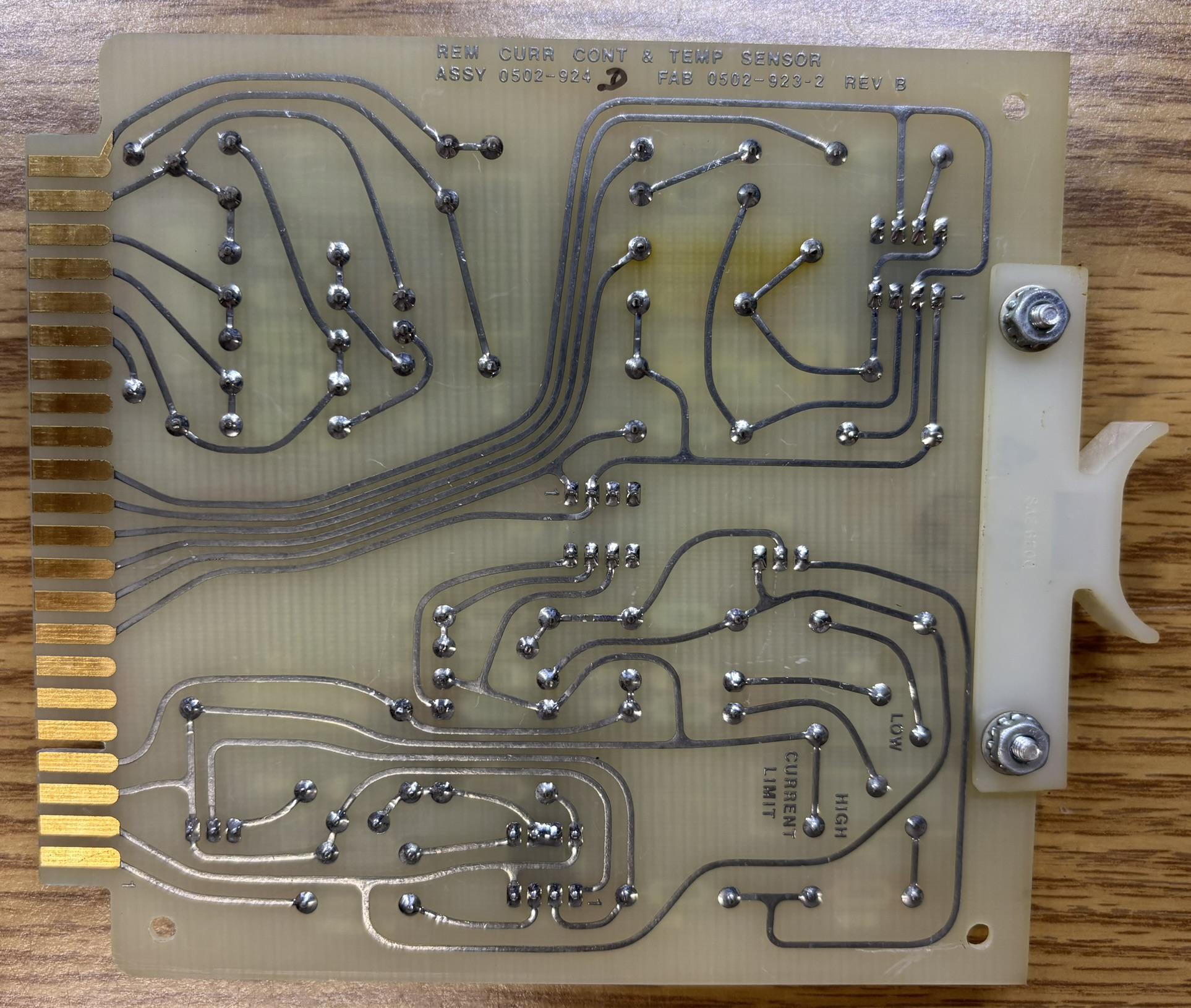
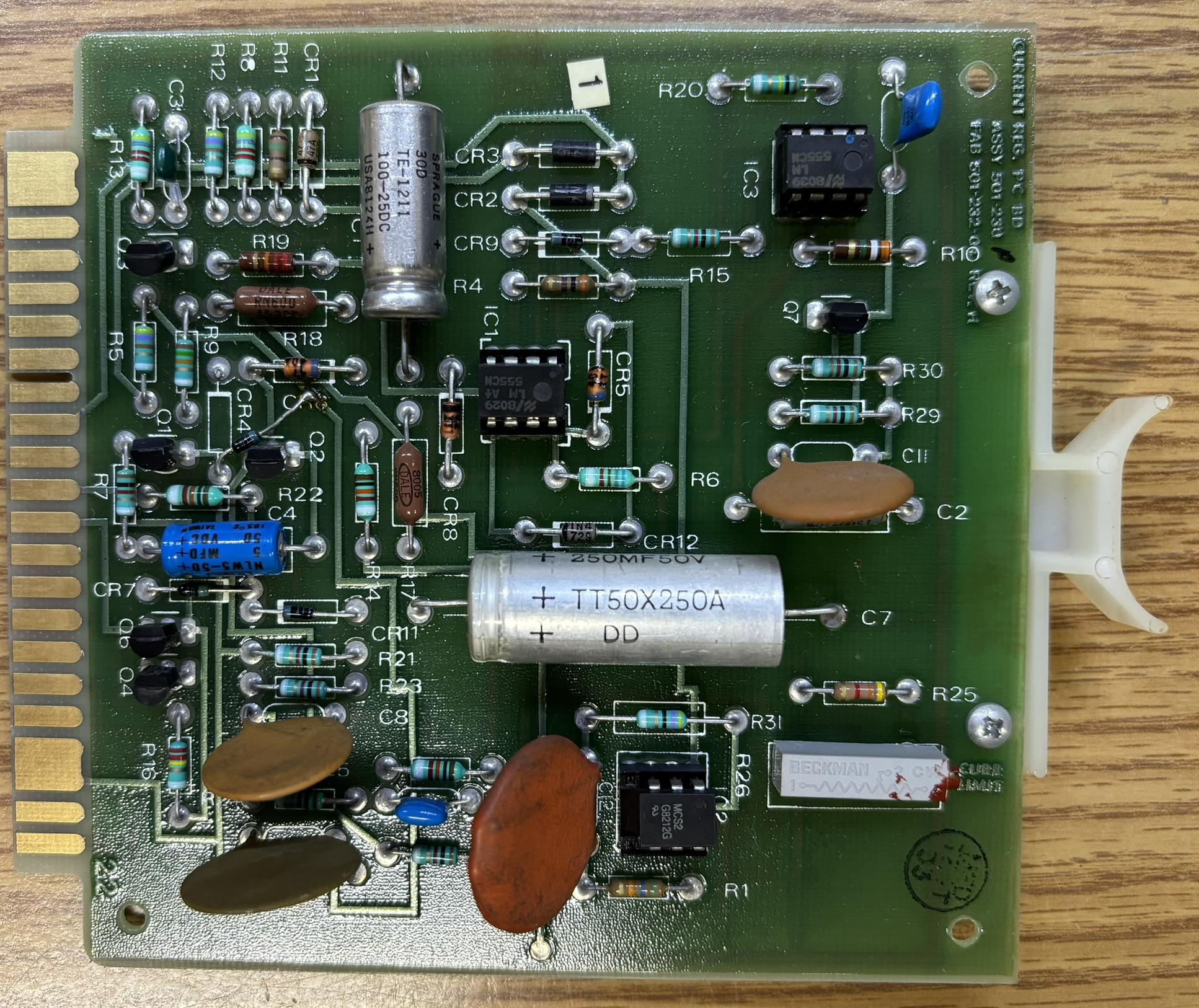
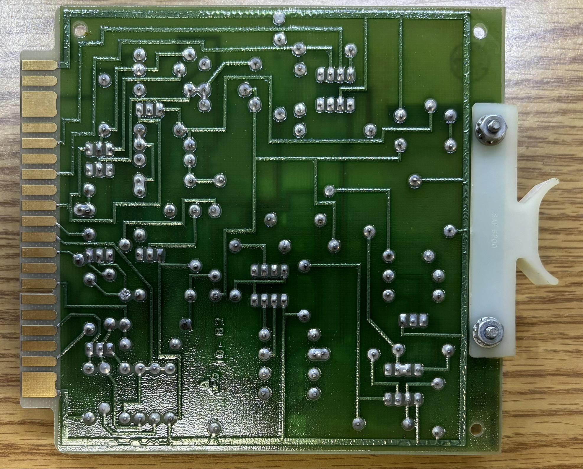
This is the remote current control and temperature sensor card that plugs into the J17 edge connector. The two potentiometers allow for changing both the high and low current limit.
This is the current regulation control card that plugs into the J16 edge connector. This board has a single potentiometer for adjusting the current limit.
This is the auto fill control card that plugs into the J18 edge connector. It is our understanding that this card could detect when the tube pressure was low and engage the auto fill solenoids as needed to add argon gas to the plasma tube.
Additional Components
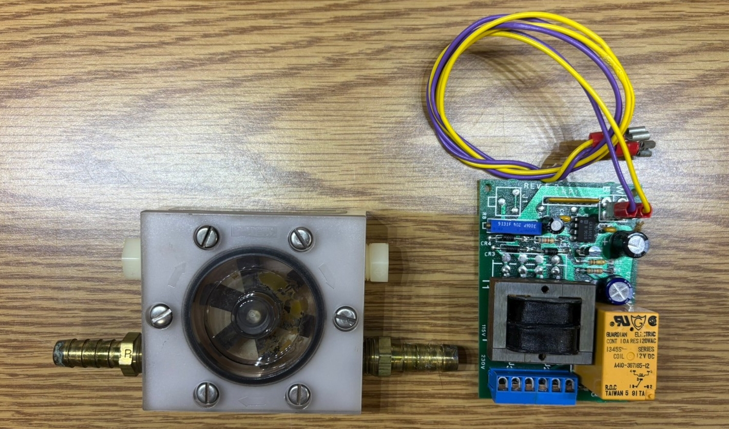
A Proteus model 100CT fluid flow switch is installed in series with the water cooling loop and connected to a small control board. The flow switch monitors the water flow and uses NO/NC outputs to open the interlock circuit if the flow rate is insufficient. The relay is responsible for providing the NO/NC output and the potentiometer is likely used to adjust the sensitivity or trigger threshold of water flow.
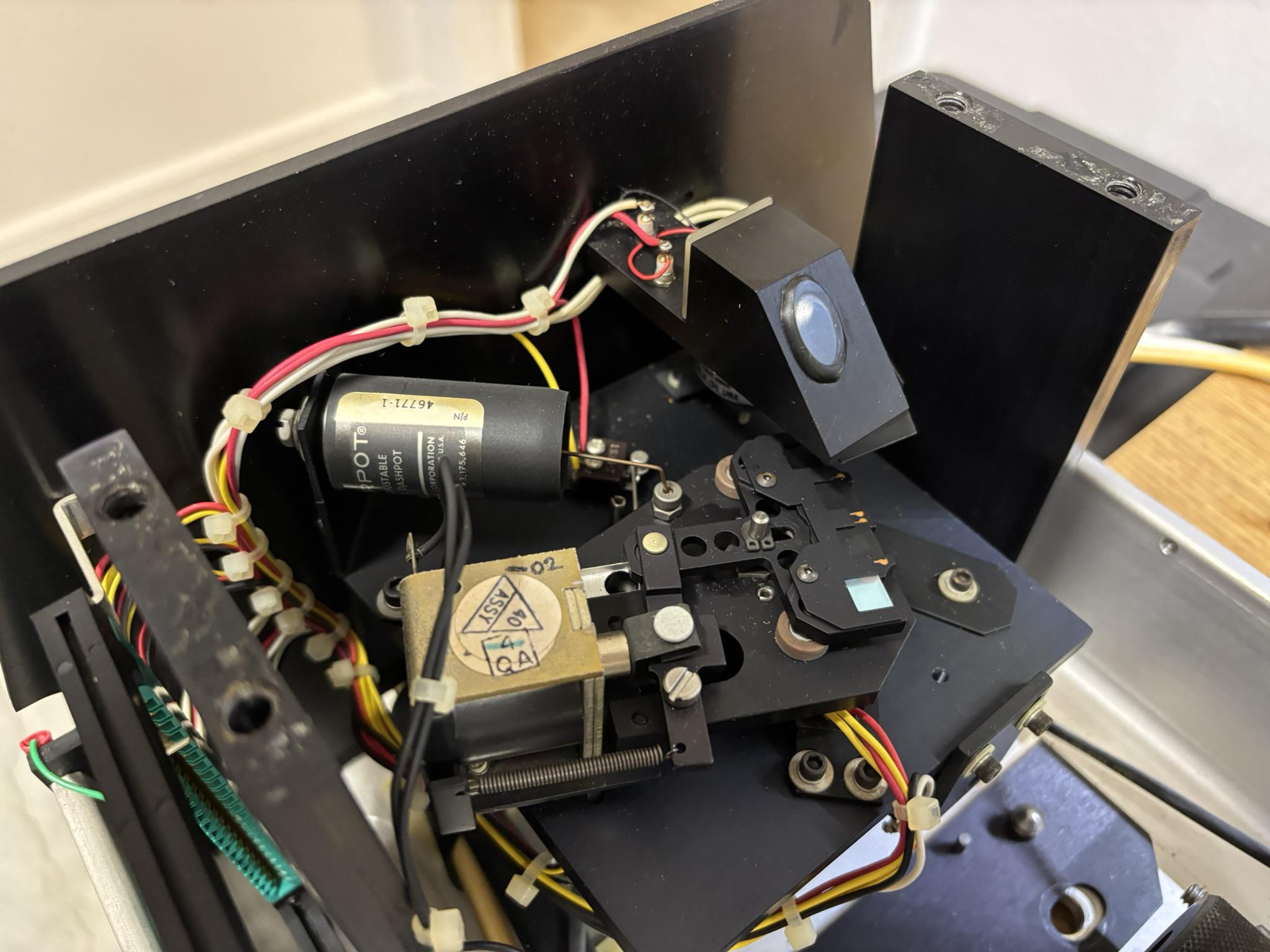
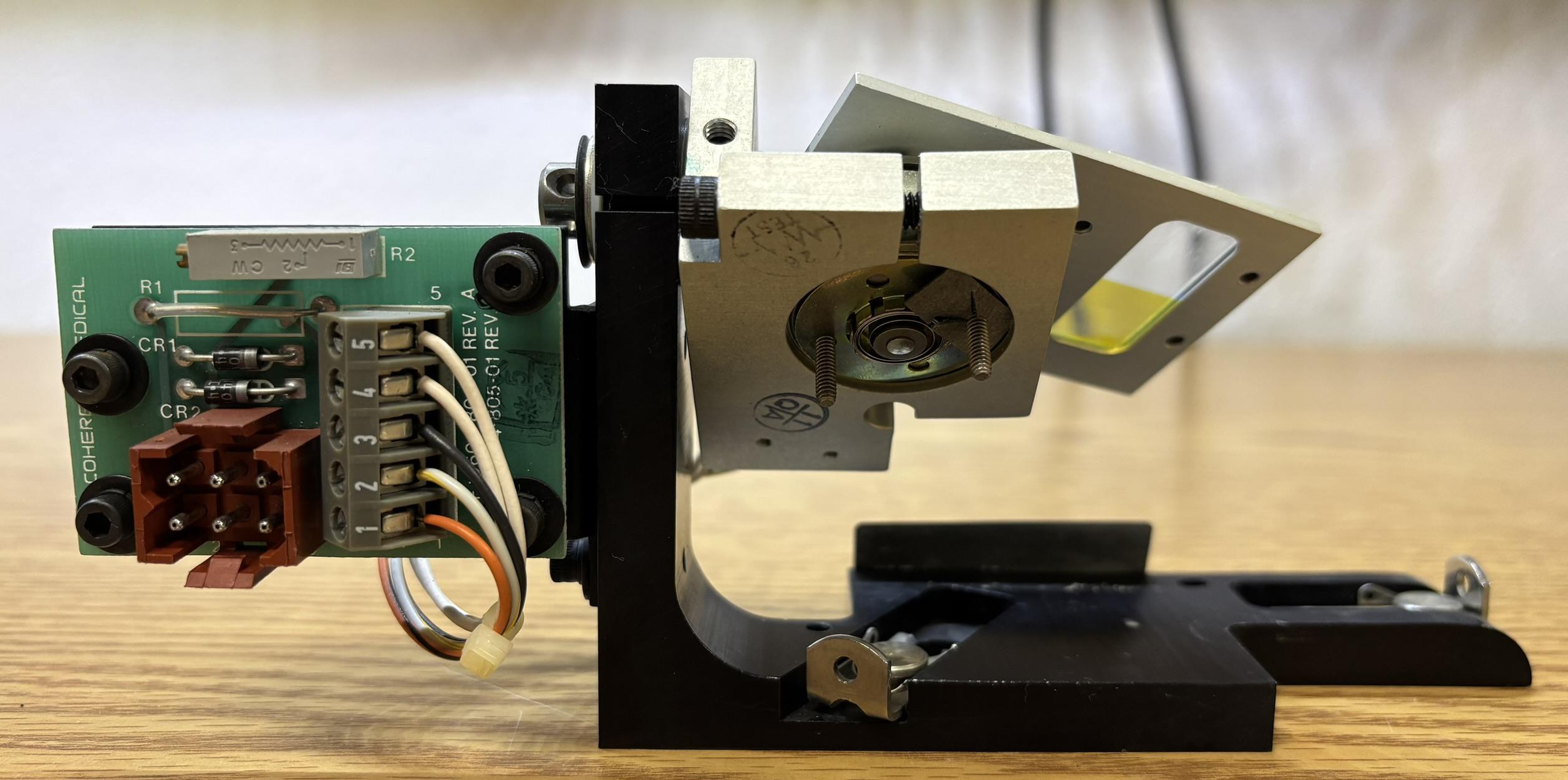
This is the electronically-controlled selectable filter and safety shutter module. It is mounted below the aluminum plate with the kinematic fiber coupling mount. The safety shutter blocks the beam entirely when required. A metal armature contains 4 slots for dichroic filters. Only one slot is populated with a dichroic filter, the remaining slots contain an opaque piece of metal. The motor can be controlled to select between any of the 4 positions to place the desired dichroic filter in the beam path. It is our understanding that this was used to select the desired wavelength for the aiming beam. An additional solenoid can be used to retract the entire set of optics, allowing the beam to pass unfiltered. There is an optical pickoff with a photodiode (wedge-shaped piece of aluminum with optic mounted at 45-degree angle) mounted directly above the safety shutter.
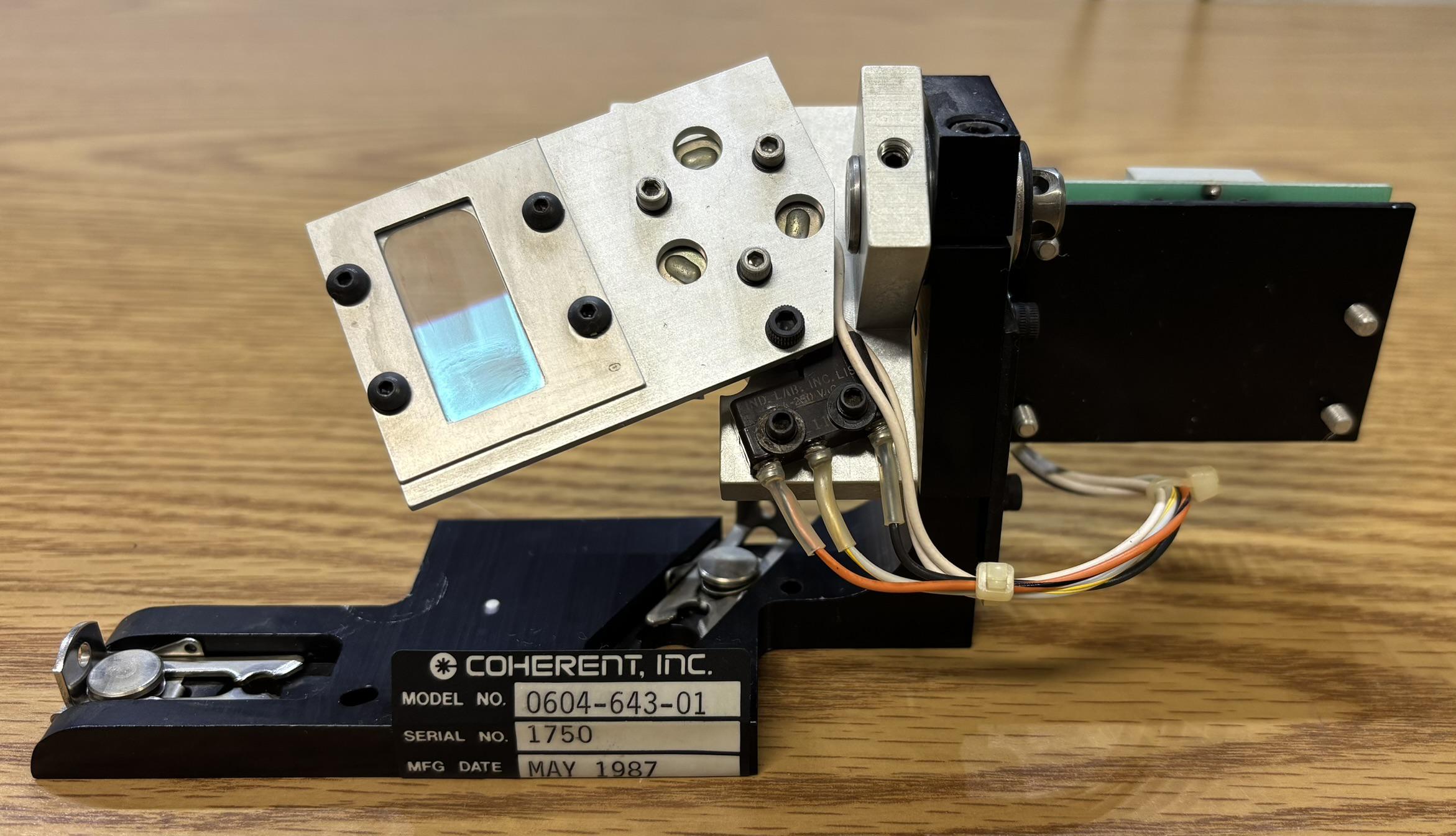
This is a two-position actuator with a dichroic filter installed. The system can select between either position to filter out different wavelengths of laser light as it shines through the optic. The dichroic filter appears to be a single piece of glass with two different coatings, which make up the two possible positions. Applying 24V DC moves the actuator to the upwards position, removing power causes it to return to the downwards position (pictured).
Due to the requirements for 3-phase power and water cooling, we aren't focusing our efforts on getting this system running right now. However, we will be keeping all the components with the intention of getting the system operational one day. Schematics for several components of this system can be found within the PDF linked below.