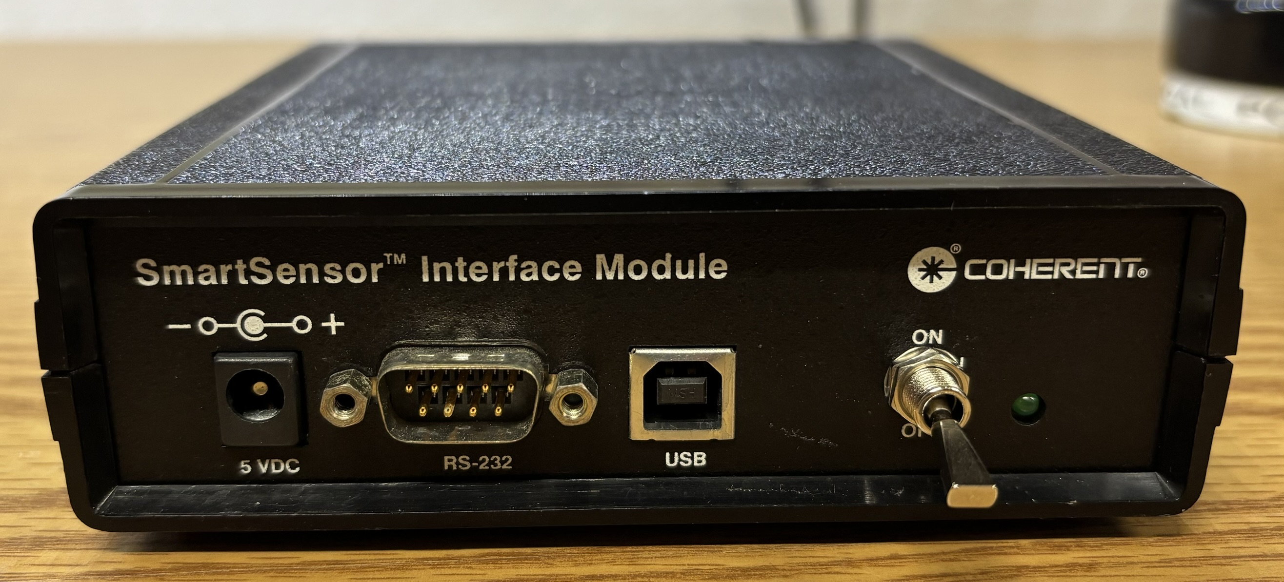
The Coherent Smart Sensor Interface Module (SSIM) is a computer-controller digital laser power meter interface that is compatible with their lineup of "smart" detector heads. Originally, software from Coherent could be used to easily interpret and display the power measurements in a GUI, but that software is long gone. However, the RS-232 serial interface is still fully functional and uses a syntax that is easy to work with. Luckily, we were able to locate the SSIM OEM tools user manual. This document explains all of the serial commands along with their functions. It also references the Coherent software used to communicate with the SSIM over USB, but since that along with the USB driver are nowhere to be found, it is of no use. Serial ports are great since they require no drivers, just a suitable serial interface on the host computer. The benefit of the SSIM over a typical laser power meter is the ability for logging and processing of the data using a computer, rather than just displaying the reading on a small LCD screen. The SSIM is a simple device, just a small plastic box with the following features on the front panel. 5V DC input barrel jack, DB-9 RS-232 serial port, USB-B connector, power switch, and a power indicator LED.
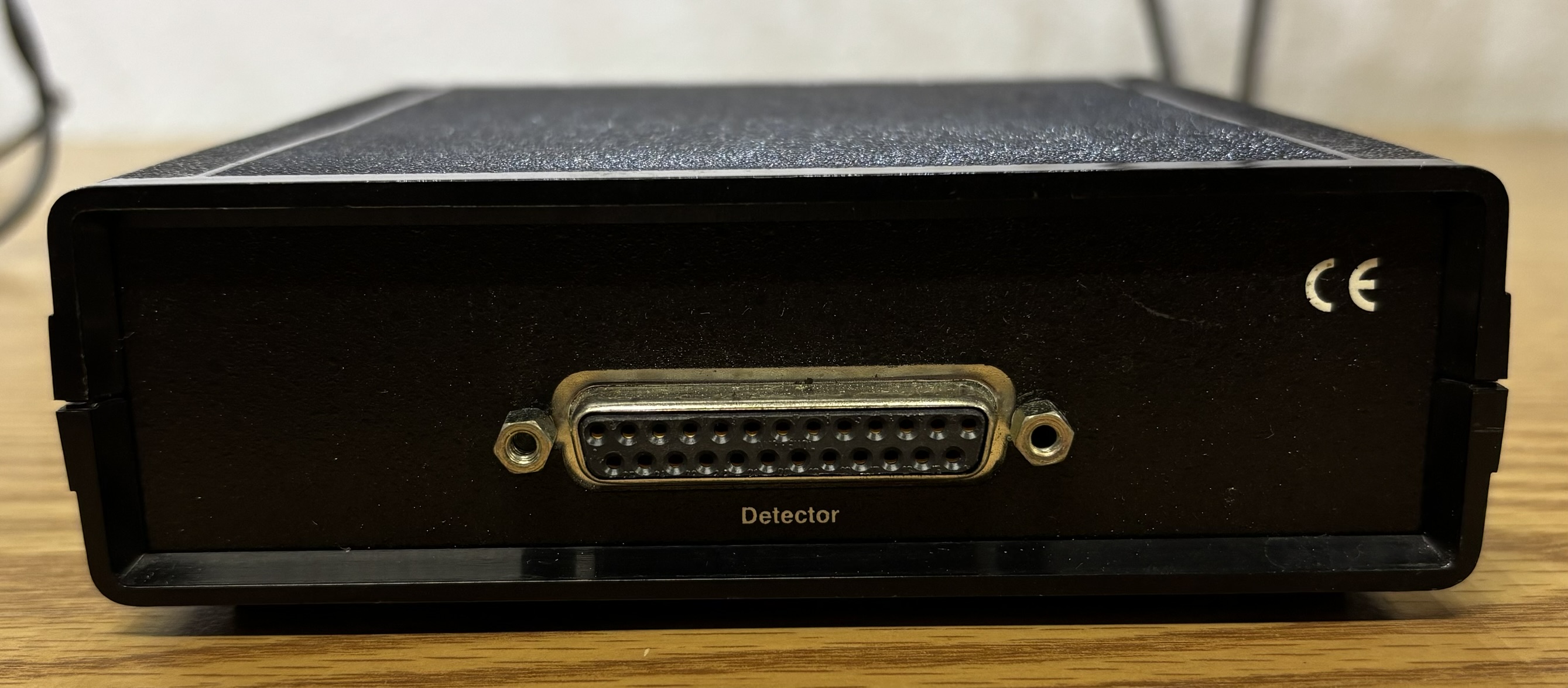
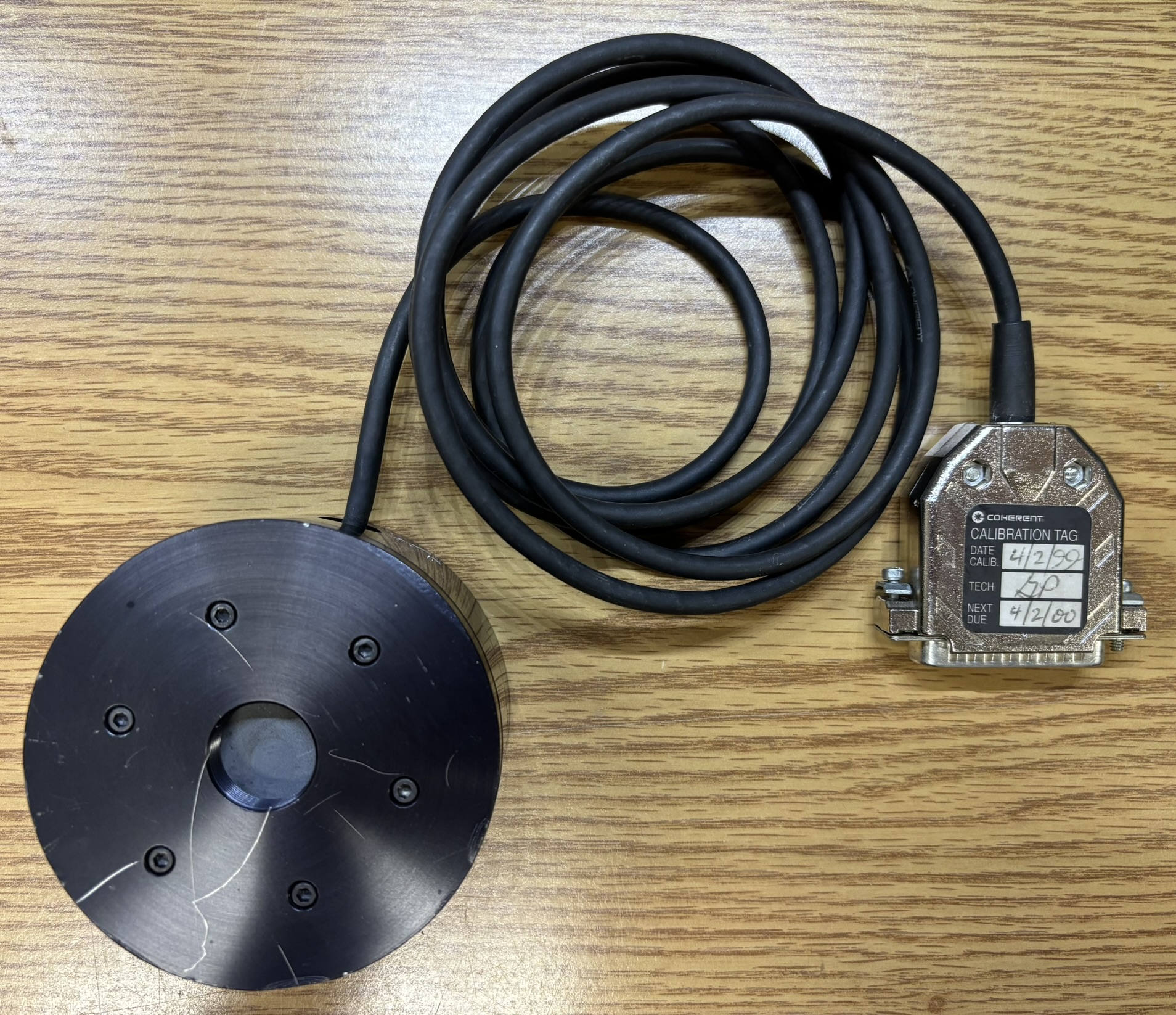
On the back, the only connector is a DB-25 for the detector head. The SSIM is compatible with many of Coherent's thermal and quantum (silicon) sensors. According to the OEM tools user manual, detector heads are even hot-swappable without powering off the SSIM.
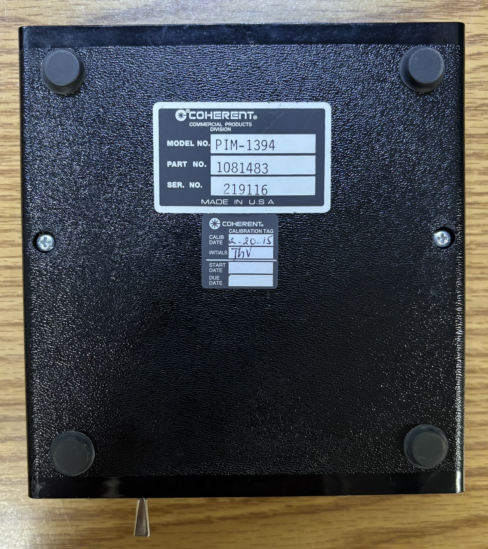
An information sticker and calibration tag can be found on the bottom of the unit. This SSIM was last calibrated in 2015, this was confirmed in the software, and the system even came with a calibration certificate.
The detector head that we received with this unit is a Coherent LM-150 FS Quad HD. According to the firmware and tag, the detector head was last calibrated in 1999. This sensor has a power range of 100 mW to 150 W with a resolution of 10 mW. It also has the ability to detect and report (in software) the position of the laser beam on the sensor surface. This is useful for centering the beam, which improves the accuracy of the power reading.
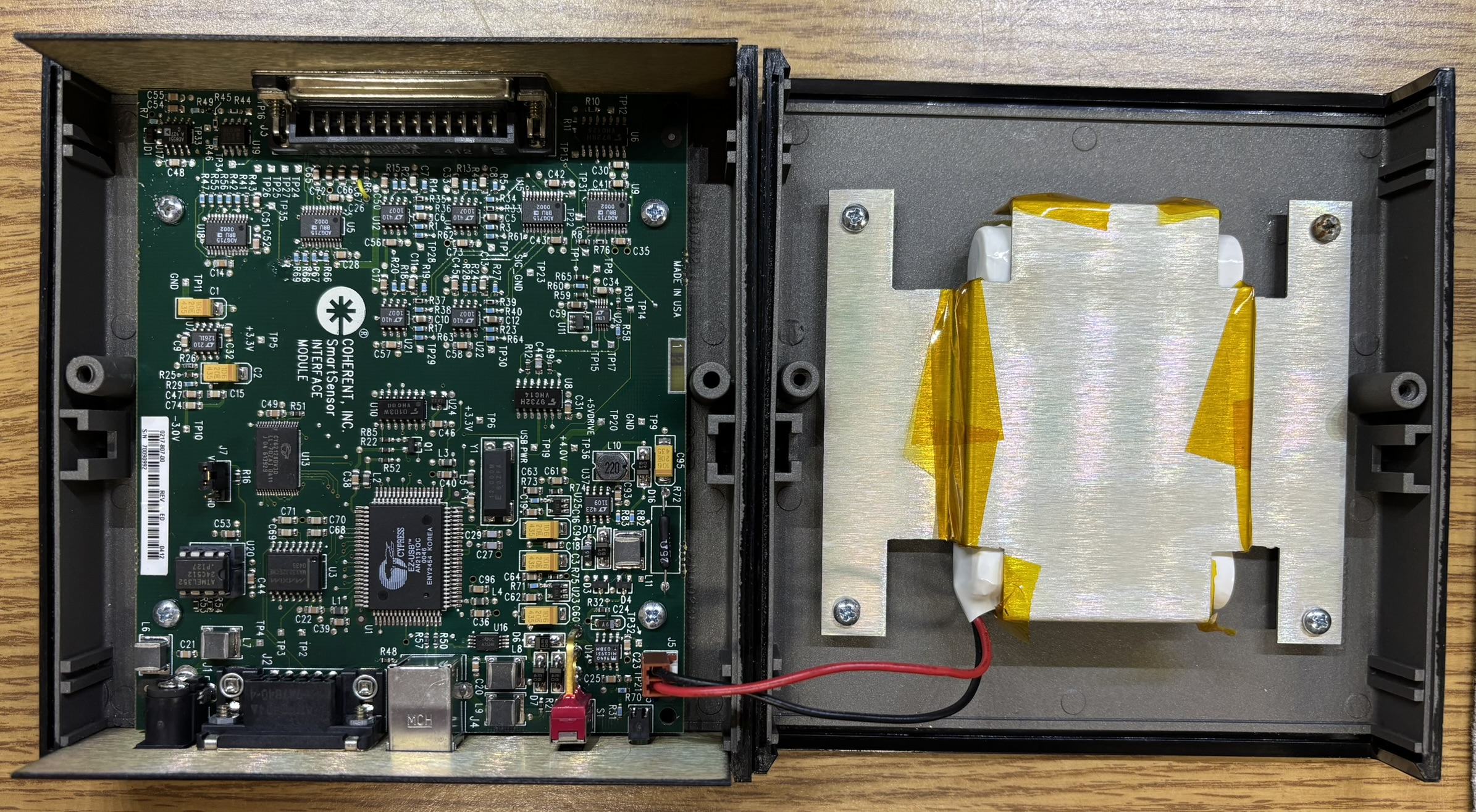
Taking a look inside the SSIM reveals the main circuit board mounted to the bottom half of the case, and a NiCd battery pack mounted to the top half of the case. The SSIM can be powered by the internal battery, DC barrel jack, or the USB port. The large Cypress chip is an EZ-USB controller IC which facilitates USB communication and also includes numerous other features. We dumped the contents of the ATMEL 24C512 serial EEPROM and have included links to the HEX and ASCII dump files below. There are some interesting undocumented programming and calibration commands contained within the EEPROM. However, the SSIM will not process these commands unless it's in calibration mode. We are currently not sure how to enter calibration mode.
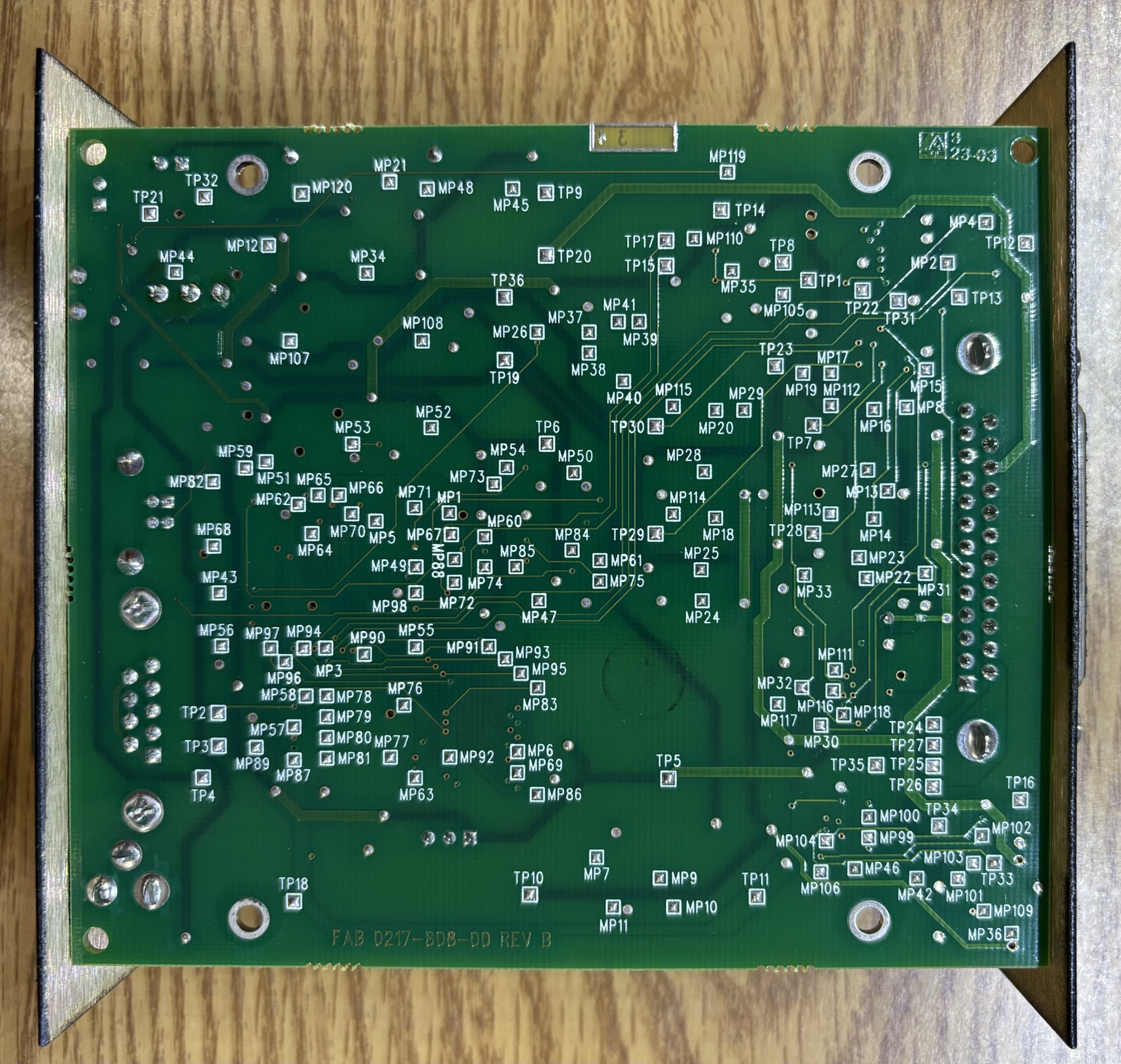
There are no active components on the back of the 4-layer board, just a large amount of test points.
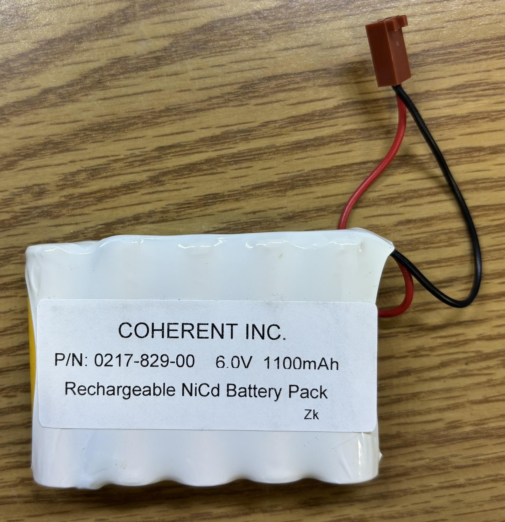
Here is a closer look at the NiCd battery pack, which we removed from the SSIM as it was quite old and starting to leak. Luckily it had not leaked on to the circuit board yet.
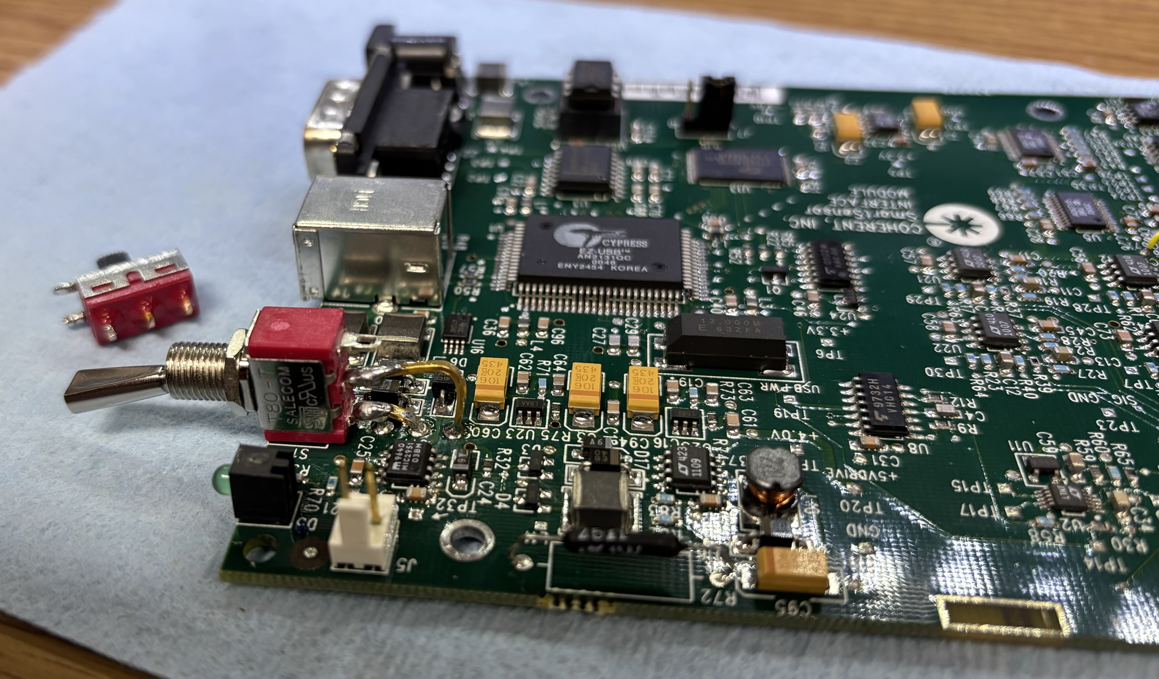
The main challenge that we faced with our SSIM was the fact that it simply would not power on. We tried the barrel jack, USB port, and even supplying 6V DC to the battery connector. Nothing worked until we eventually tested the polarity of the power switch. We tested all the switch contacts and it was completely open circuit in either position. We decided to replace the original sliding switch with a small toggle switch. It fit perfectly and only required minor modifications to the front panel. The SSIM powered on without any issues after the new switch was installed.
Connecting to the SSIM over the RS-232 serial interface is pretty straightforward. You will need a crossover (null modem) cable or adapter. There is no baud rate documented in the user manual, but after testing common baud rates, we determined that it communicates at a baud rate of 19200. There does not seem to be any way to change the baud rate of the SSIM. The full serial communication parameters are as follows (abbreviated): 19200 / 8 / N / 1. The user manual does include a list of serial commands with descriptions. This allowed us to get our SSIM up and running quickly, without having to guess commands. We have provided a few commonly used commands below, refer to the user guide for the full list of commands.
| COMMAND | DESCRIPTION |
|---|---|
| *ind | Request hardware identification |
| mcal? | Request SSIM calibration date |
| h | Request help menu (list of commands) |
| cal | Request detector calibration date |
| dt? | Request detector model name |
| wv? | Request the currently selected wavelength (meters) |
| dst | Begin data stream |
| dsp | Stop data stream |
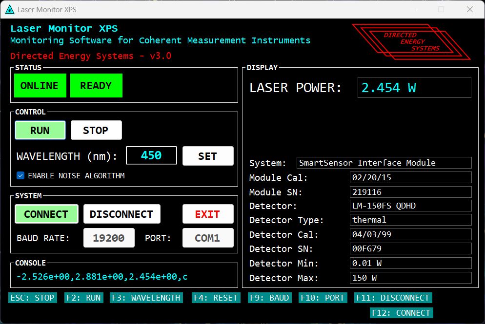
The most useful function is the data stream, which will output a line 10 times per second that contains the x position, y position, power reading, and status. See example below:
*0.125e+00,1.000e+01,1.500e+00,c
Essentially all numeric values are in scientific notation and will need to be converted to be human readable. We have written a simple GUI program to interpret and display data received by the SSIM on a Windows computer. The software is called LaserMonitorXPS and can be downloaded via the link at the bottom of this page. Feel free to provide feedback for the software as we are always looking to improve!