This laser was purchased online in unknown condition, like many of our others. It was listed as "pulled from a working system", but that can mean many things. Upon arrival, the laser head and power supply came with several accessories including a fiber with a metal jacket that had been damaged, kinematic fiber mount, and an additional power control box. It seems that this laser and power supply were pulled from a piece of scientific equipment as they were definitely set up for OEM use. The laser and power supply each came mounted to a thick piece of painted aluminum and the power switch and key on the supply were both in the ON position! The "power control box" mentioned earlier was an interesting extra. It contained 2 IEC 20A connectors, one for input, and one for output, and some solid-state relays in series with both the line and neutral of the connectors. The control terminals of the solid state relays were wired directly to a DB-9 connector. There was some additional wiring and connections but they weren't anything notable. In it's original application, this laser was likely controlled entirely by computer or remotely using the relays to energize the laser power supply, then the P2 interface connector was probably used to control laser power and interlocks. The interlock key and power switch were likely only operated a handful of times as they were both a bit stiff at first.
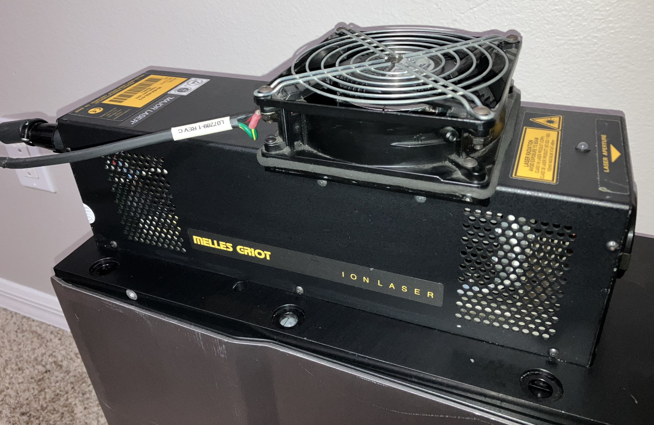
The first step was to get AC power ready to go. We fabricated a custom power cable with a Neutrik powerCON on one end and an IEC 20A connector on the other end. The powerCON connects to a custom voltage/amperage meter box with contactor disconnect. The IEC 20A connector plugs right into the front of the power supply. After this, we connected the huge multi-pin umbilical cable to the power supply and then to the laser head only after inspecting all of the pins on either end for corrosion or damage. A damaged umbilical cable or pins can lead to high resistance or arcs which gets very dangerous very fast! The 24V DC fan on the laser head also needed to be connected to its respective plug on the back.
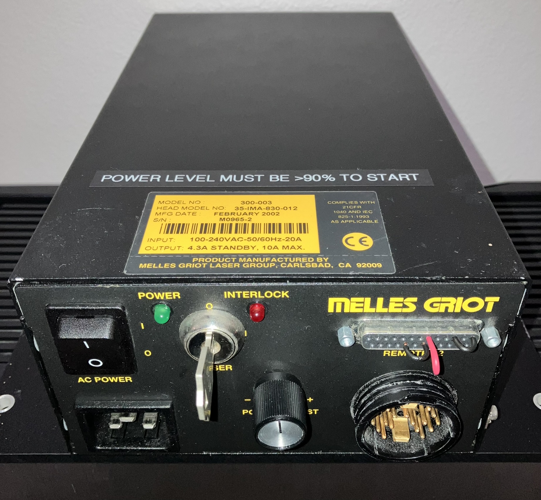
Next was obtaining the pin-out for the P2 remote interface DB-25 connector on the power supply. This contains many I/O including interlock signals which must be satisfied or else you won't get any beam output. Luckily, Sam's laser FAQ made this a breeze. A condensed version of the pin-out is provided below, please visit Sam's website for the full version. The model of this particular power supply is 300-003, but this pin-out seems to work on many of the common Argon Ion laser power supplies. The minimal connections needed to operate the laser are pins 1 to 3 (beam interlock), pins 19 to 21 (safety interlock), and pins 7 to 18 (light control mode using power supply potentiometer). At this point, AC power can be turned on which starts the fans, it is quite loud as both the power supply and head fans run at full speed during laser operation. They spin-down after about 2 minutes when the interlock is not closed. The green power LED indicates good AC power, and the red interlock LED indicates the beam interlock is closed. The key switch is in line with the safety interlock. If you have connected the standby pins, the orange standby LED will turn on. We built a custom control box with a DB-25 plug that connects to the power supply and allows control over the laser with switches instead of using jumpers to connect the pins. It also uses an Arduino to monitor the current and output. There are OEM purpose-built control boxes for these systems but they are expensive and difficult to find. A link to our controller project page is provided below.
| PIN |
PURPOSE |
|---|---|
| 1 |
BEAM INTERLOCK OUT |
| 3 |
BEAM INTERLOCK IN |
| 4 |
STANDBY MODE |
| 6 |
CURRENT CONTROL INPUT |
| 7 |
LIGHT CONTROL INPUT |
| 8 |
OUTPUT POWER MONITOR |
| 9 |
TUBE CURRENT MONITOR |
| 11 |
CIRCUIT GROUND |
| 12 | -15 VDC |
| 13 | +15 VDC |
| 17 |
5.1 VDC VOLTAGE REFERENCE |
| 18 |
POTENTIOMETER OUTPUT |
| 19 |
SAFETY INTERLOCK OUT |
| 21 |
SAFETY INTERLOCK IN |
| 23 |
PSOK SIGNAL RETURN |
| 24 |
PSOK +5 VDC |
| 25 | CHASSIS GROUND |
This unit did not start up immediately and took some convincing to get going. Once powered up, most Argon Ion lasers will begin heating the cathode and strike the tube and (hopefully) begin lasing around 45 seconds later. Initially we had the power level set to the minimum, essentially standby mode, when powering this unit up because we were unsure of the condition. We could hear the power supply click three times when it was trying to strike the tube but it did not run. We also observed extremely high amperage spikes on the AC input side, up to 16 amps in some cases while this was happening. Taking the laser out of standby mode and turning up the current to a near maximum 90% allowed us to strike and run the tube reliably. Why is this the case? Further research and collaboration with laser repair specialists revealed that most Argon Ion lasers are actually supposed to be started around near maximum current. Additionally, older tubes like this one with high running hours, can be hard to start and some even struggle to run at low current levels. It is best to operate the tube somewhere in the middle when its health and history is unknown. Generally, lower current = longer life, but if the current is too low, the tube may not start and could even be damaged by the power supply repeatedly attempting to strike it. This can also damage the power supply itself.
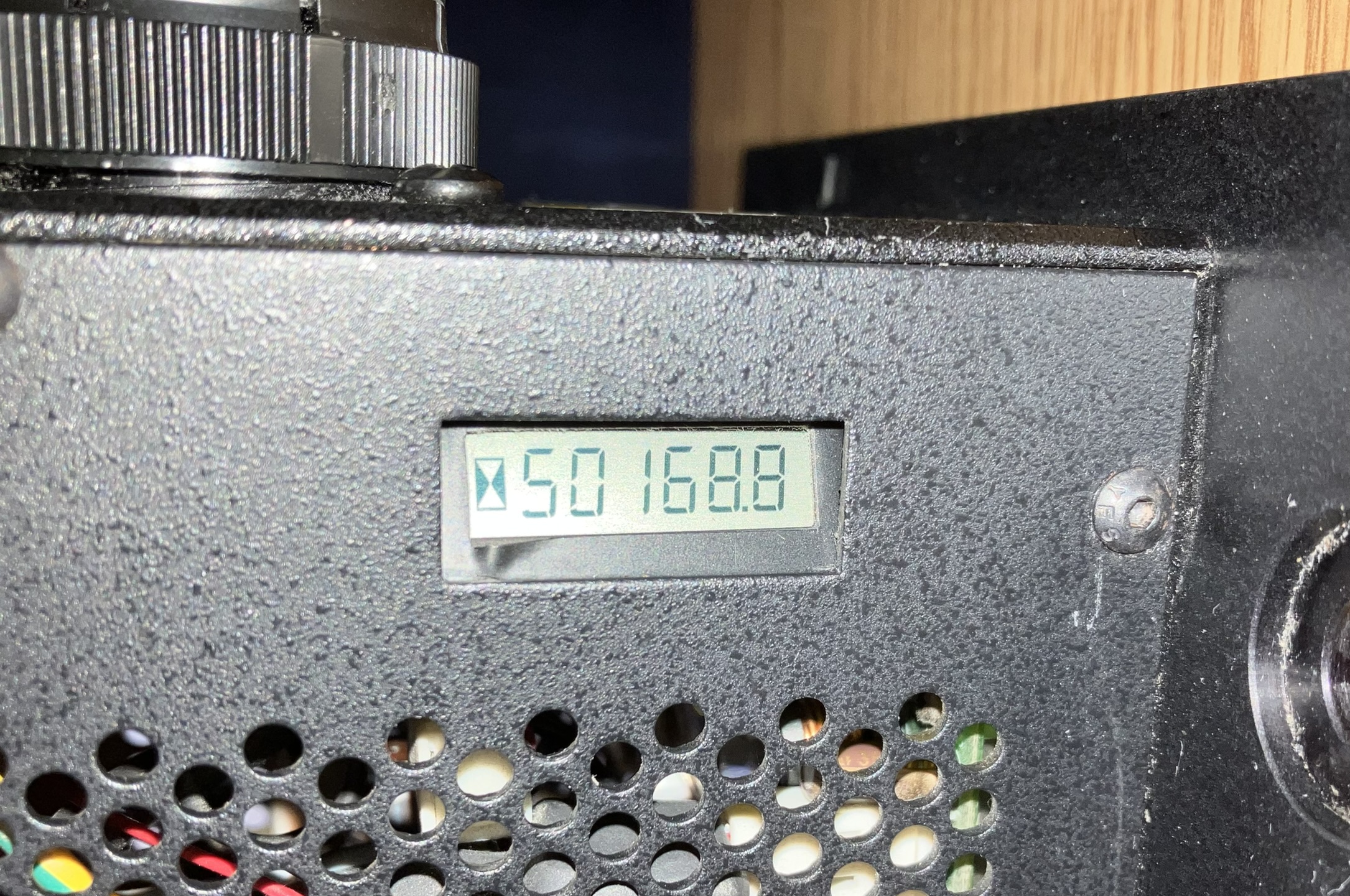
The built-in hour counter on this unit displays over 50,000 hours which is quite a bit, but does not take into account any tube replacements or service. Combining the potentially high hours with the difficulty to start, we decided to do a burn-in run on this laser. We ran it nonstop at 50% power level for about 4 hours. This is to combat a common problem with gas lasers that aren't run for a while. Essentially, gas released from the tube walls can build up to a level that prevents the tube from starting. By running the laser at an adequate power level for extended time, excess gas and contaminants are buried back into the glass. Oudin coils are a common way to get tubes in this condition going again. Be sure to exercise caution when using Oudin coils or other external means of starting the laser as arcs near the tube ends or brewsters can puncture through the vacuum seals or glue. Luckily, ours only required an increase in power level during start. It runs fine from standby to maximum current once already started, but as mentioned earlier, it's a good idea to run it close to the 50% mark. To combat this gas buildup, simply run your gas lasers for at least 30 minutes every couple of weeks being careful not to overheat or overdrive them.
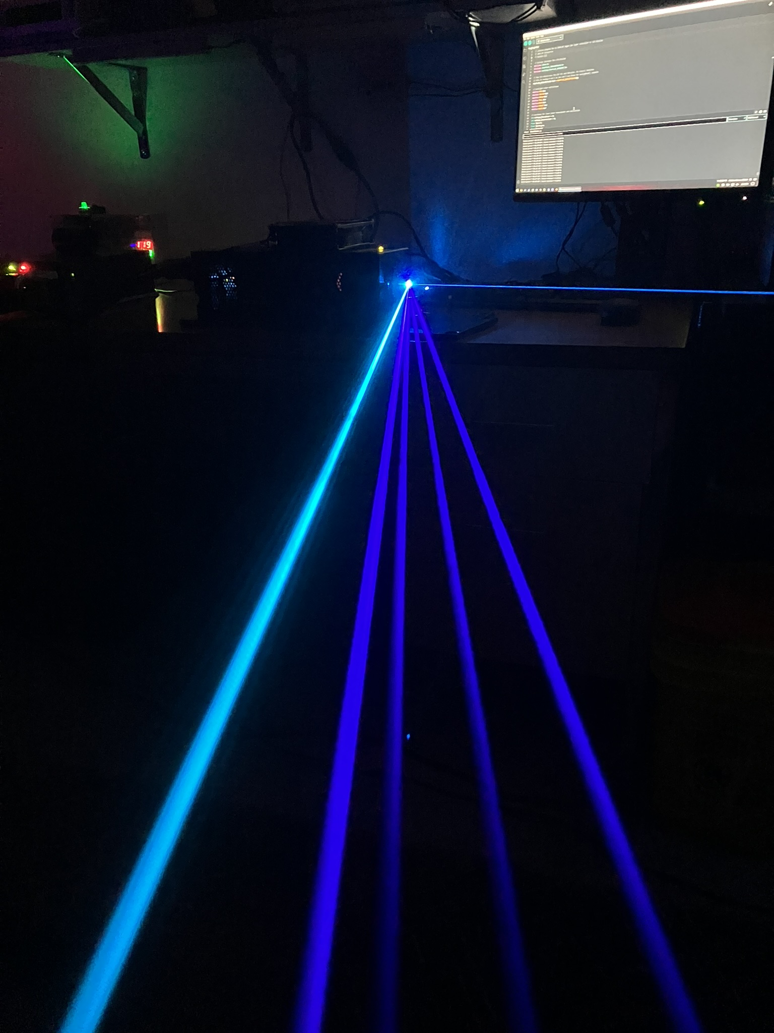
One of the most impressive things about Argon Ion lasers besides their insane power consumption is their ability to simultaneously output several beams of different wavelengths. Some Argon Ion lasers are multiline, meaning they output multiple wavelengths, others are configured to be single line where other unwanted beams are filtered out. The highest end Argon Ion lasers can even be tuned to different wavelengths while running. The 488nm beam often appears as most intense but is not necessarily the most powerful due to differences in conversion efficiency. By placing a diffraction grating in the beam path, the different wavelength beams can be visualized on a piece of paper or as individual beams when a fog machine is used.
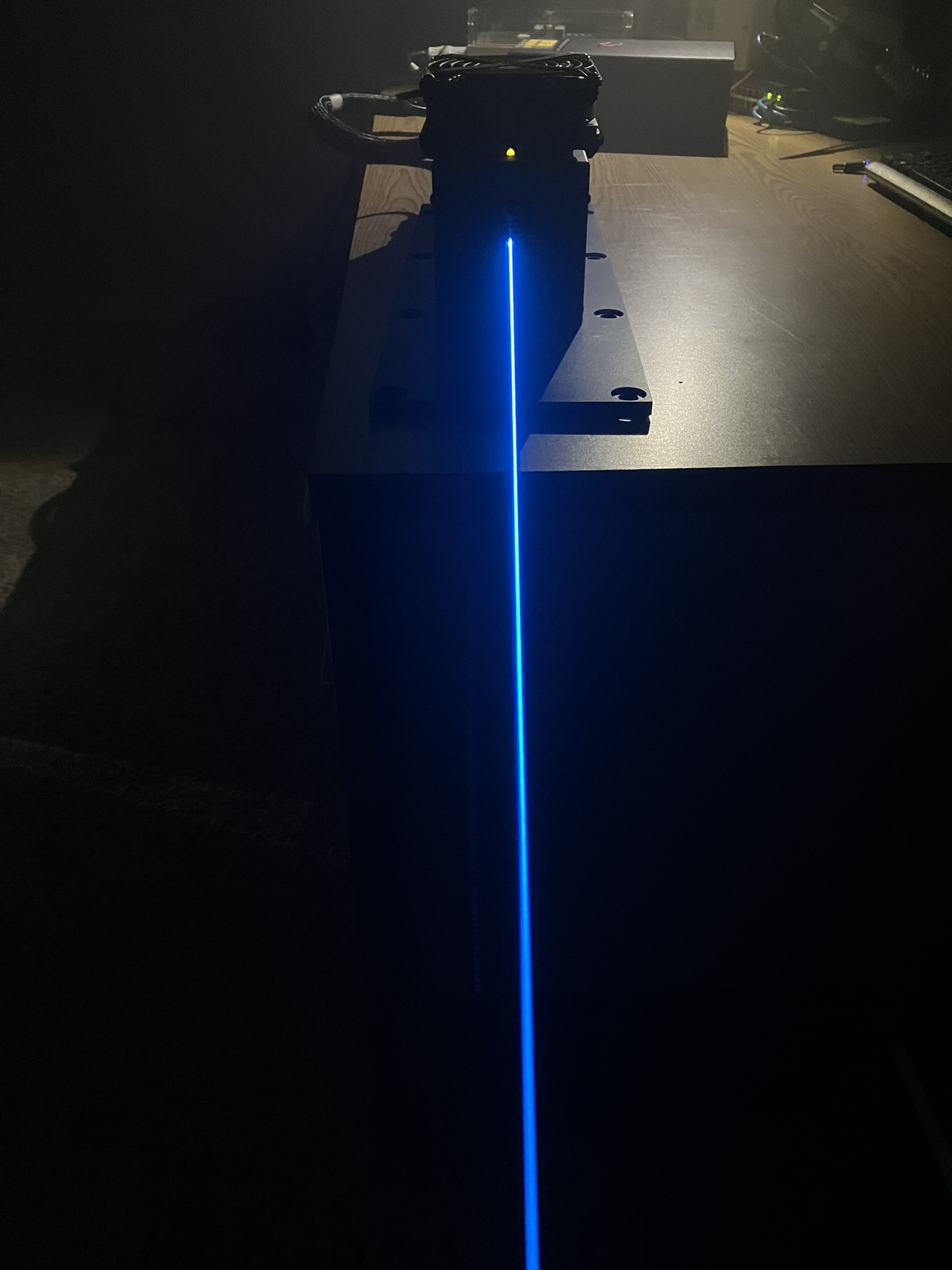
We really need to get a laser power meter around here as we have not been able to precisely measure the output of any of our lasers so far! Despite this, we were able to estimate the output power of this laser to be ~35mW when running at 50% current. This was done by taking a voltage reading from the laser power monitor pin on the power supply DB-25 connector. This cannot be relied upon unless the laser head and power supply match and were originally paired together as they have to be calibrated to output an accurate reading. We are nearly certain that this power supply and laser head match so we accept this reading.
As usual, Sam's laser FAQ is a great resource and was where we located the pin-out for the P2 interface connector. Also a special thanks to Zenodilodon for helping me get this unit running and for providing advice on how to keep it running! Appreciate ya!