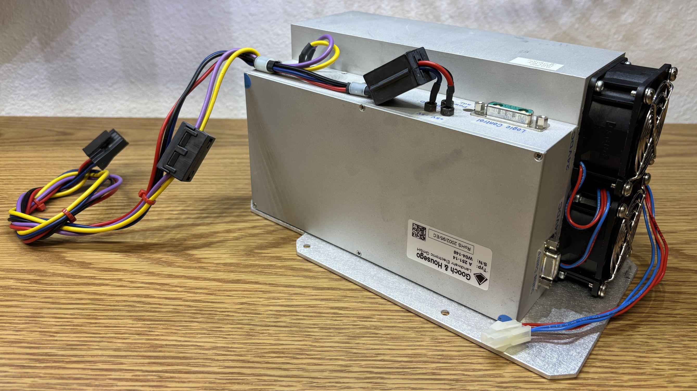
Older HPS models will have a Landwehr branded q-switch driver while newer models will have one branded Gooch & Housego and Landwehr. This device generates the RF energy to drive the q-switch crystals located within the resonator and pulse the laser. This pulsing allows for higher laser output power levels and modulation of the beam. According to the XPS service manual, the successor to the Greenlight HPS, the q-switch repetition rate is 15-22kHz in vaporization mode and 12Hz, 25% duty cycle in coagulation mode. The driver is air cooled by two fans and we estimate that it can output 75-100 watts of RF energy. A sticker on the side of the resonator leads us to believe it's set at 75 watts. Since the driver is DC powered, all connections route to the rear panel board. Additional connections include a D-SUB connector with two coax terminals labeled LOGIC CONTROL, and a 9-pin D-SUB connector labeled STATUS CONTROL. Problem 102.9 asserts when disconnecting the AOM driver LOGIC CONTROL connector while the system is running.
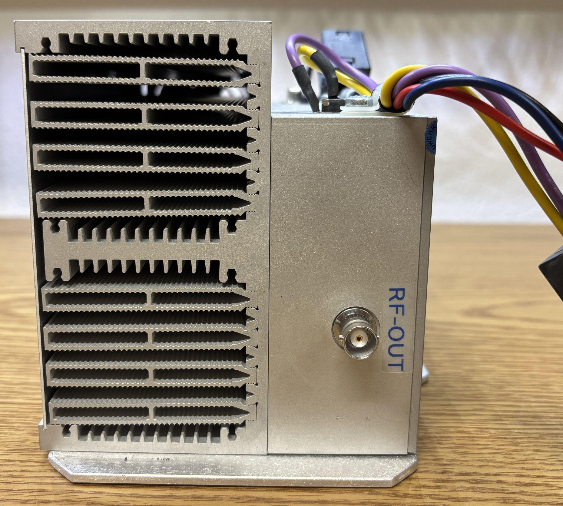
This AOM driver is air cooled, as evident by the large heatsink secured to the smaller electronics enclosure. Visible on this side is the BNC connector for the RF output to the crystals.
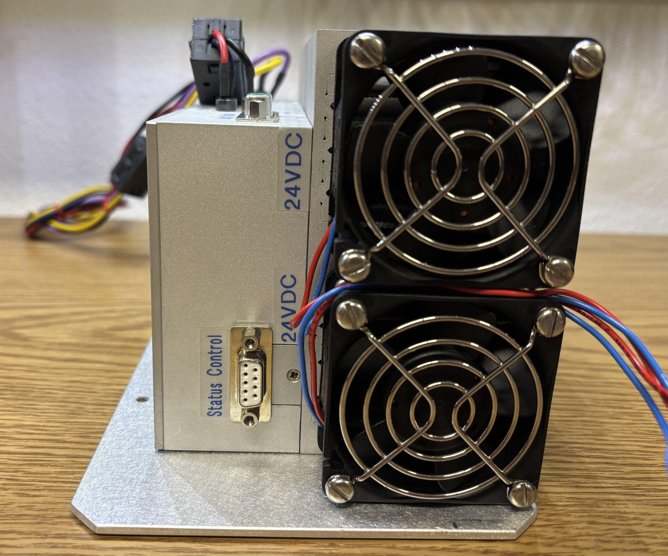
On this side are two fans, which get their power directly from the rear panel board of the Greenlight HPS. According to the labels, the fans operate as 24V DC. Also visible on this side is the 9-pin status control D-SUB connector. We have not been able to determine the pin-out for this connector, due to the complexity of measuring the system in circuit. It is our understanding that it just used to detect the presence, operational status, and maybe some basic pulse feedback. There is unlikely to be any digital communication over this interface.
On the top is the aforementioned LOGIC CONTROL connector and power input connections. The power connections are just studs to which wires are directly soldered. The logic control connector carries the analog and digital modulation signals along with a fault output and an interlock signal.

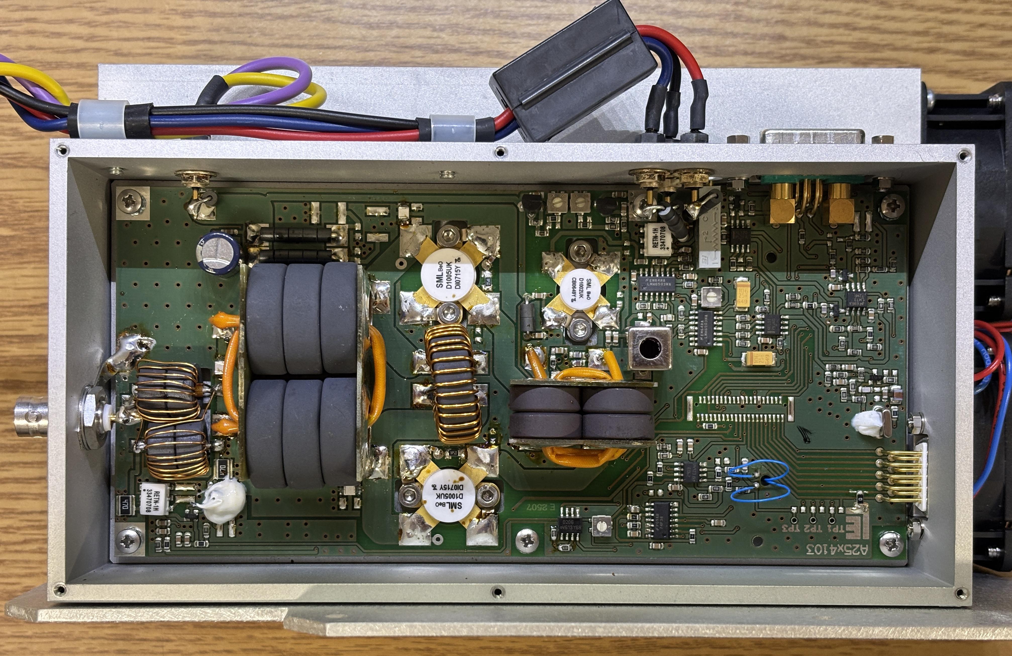
With the top cover removed, the circuit board is visible. This arrangement of components is similar to other q-switch drivers we have worked with, just scaled up a bit. Two SemeLab D1005UK and one D1002UK RF silicon fets are doing the heavy lifting in terms of RF power modulation and switching. There are numerous potentiometers and adjustment points, indicating a high degree of tunability. Markings on this board indicate an A25x model, but the datasheet and product image from Landwehr, along with the connections lead us to believe it's heavily based of the A24x variant.
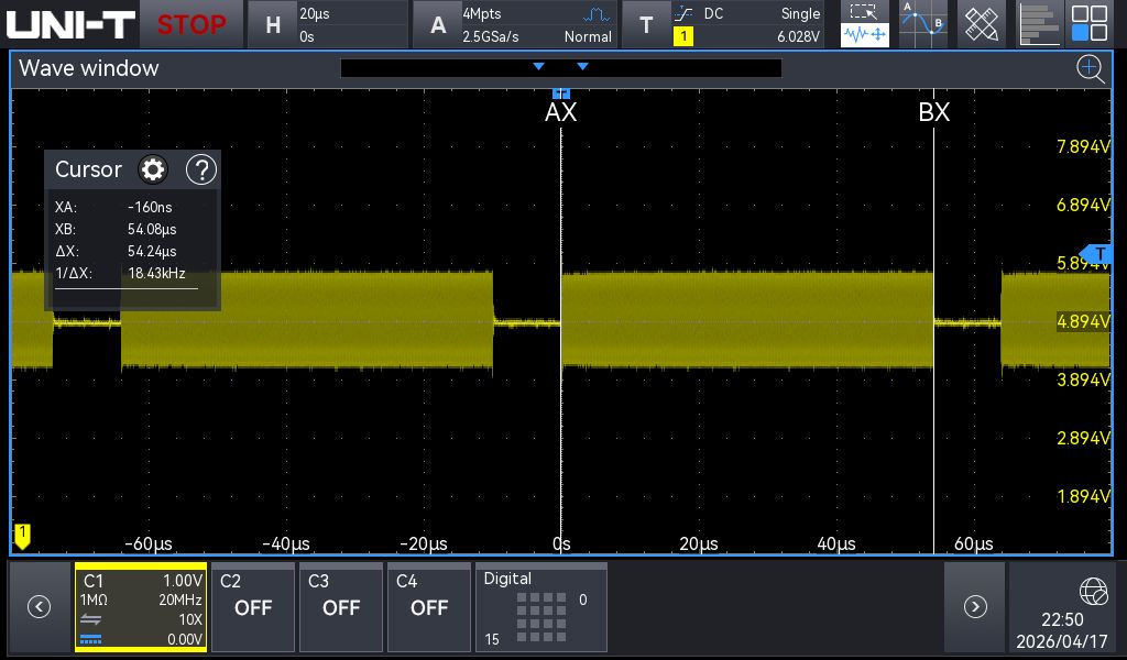
Probing the modulation inputs with an oscilloscope during operation reveals a pulse rate within the range mentioned in the service manual. In the screenshot below, it seemed to be around 18 kHz. The system does seem to implement first pulse suppression as well in order to prevent optical damage and a surge of output power when emission begins.
The datasheet linked below contains the majority of critical information related to this Q-Switch driver. The one omission is the STATUS CONTROL interface. That's not documented anywhere, and not present in the datasheet, even in the images. We presume that the STATUS CONTROL interface was a special add-on requested by Laserscope/AMS specifically for this system.