This is the embedded chiller from the AMS Greenlight HPS surgical laser system, also known as a Laserscope. This chiller, contained within the bottom section of the frame, maintains the temperature of the water loop that cools the laser diode stack, diode driver, and q-switch crystal baseplate. All of these components generate a significant amount of heat during operation, which is most efficiently removed using water cooling. The chiller uses a small evaporator and fan to dump that heat into the ambient environment. Two heat exchangers are used to move heat from the laser's cooling water loop to the refrigerant, and then from the refrigerant to the ambient air. The chiller has a pre-programmed setpoint of around 70-72 degrees Fahrenheit for the water loop. It's not a deep cool chiller, and is only intended to maintain a suitable temperature for the sensitive components. In fact, it's more of a precision chiller as it has a heater for the water loop which is periodically activated by a solid state relay to fine tune the temperature. The chiller is controlled and monitored by its own dedicated controller along with the Greenlight HPS rear panel board over RS-485. The laser system turns on the chiller and constantly monitors its status, checks for alarms, and keeps an eye on the loop temperature. If the chiller malfunctions or the loop temperature falls too far out of range, the laser will shut down and display an error message related to the chiller. The laser will not enable if the chiller fails to start or is disconnected. Conveniently, the chiller can be easily removed from the Greenlight HPS frame after removing the electrical connections, quick disconnect water fittings, and two large bolts below the yellow fan shroud and filter cartridge.
Component overview
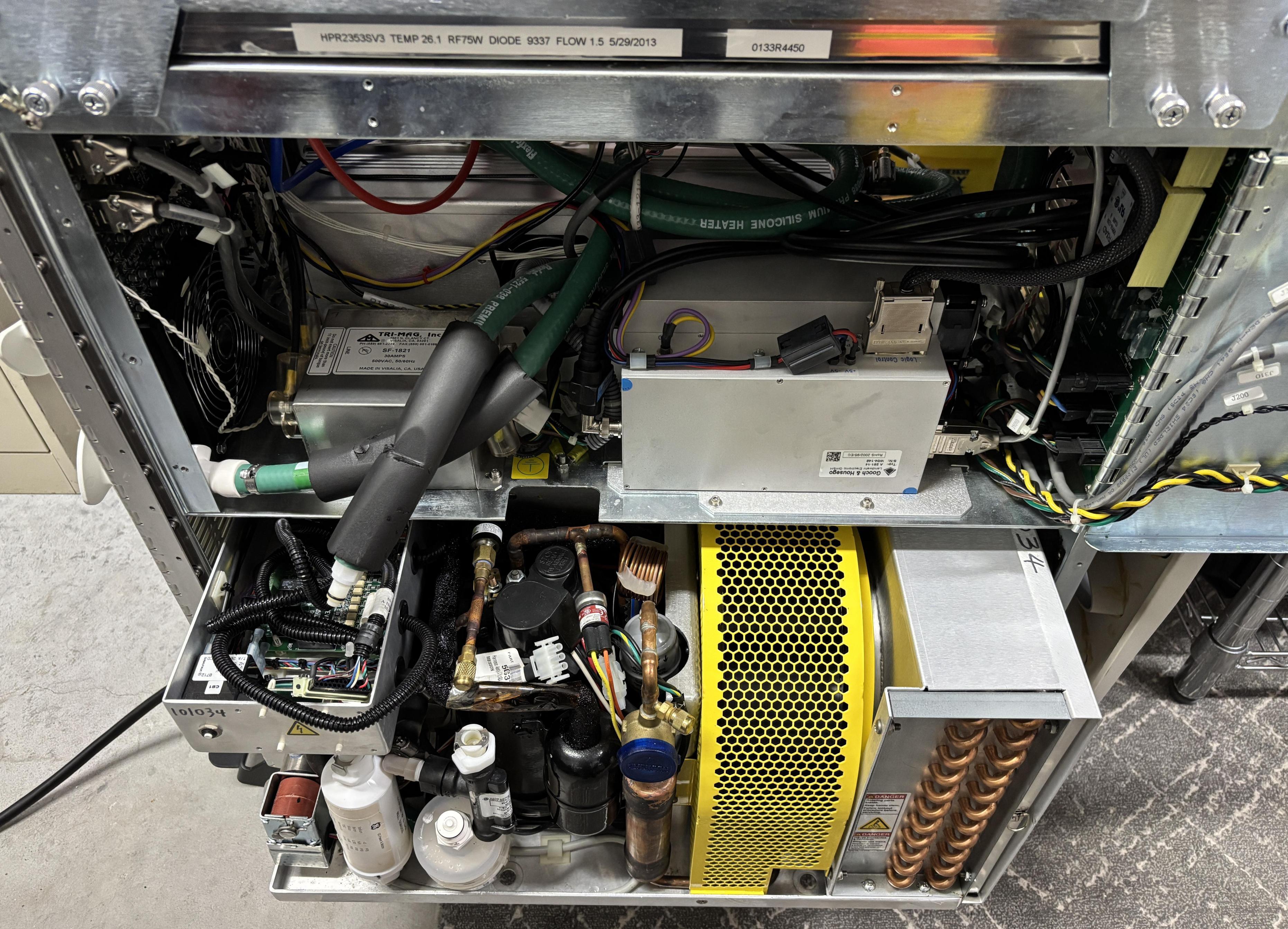
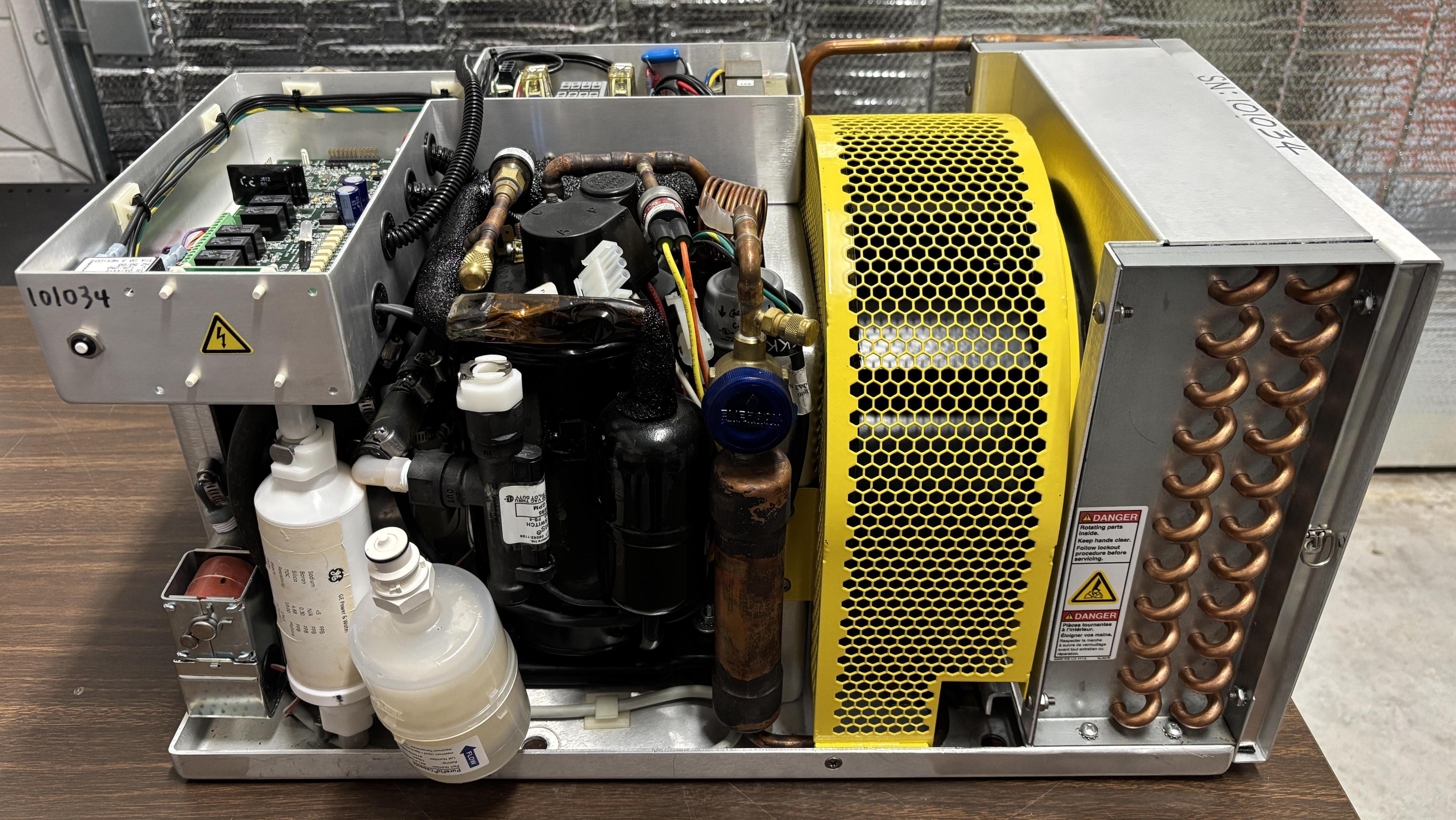
The chiller weighs about as much as a medium-sized window air conditioner or portable A/C unit and can be removed and replaced as a module or serviced outside of the laser system. It's very compact and includes several critical components such as the compressor, evaporator coil, evaporator fan, water pump, sensors, water reservoir, and digital control board. According to the information label, it uses R-134A refrigerant.
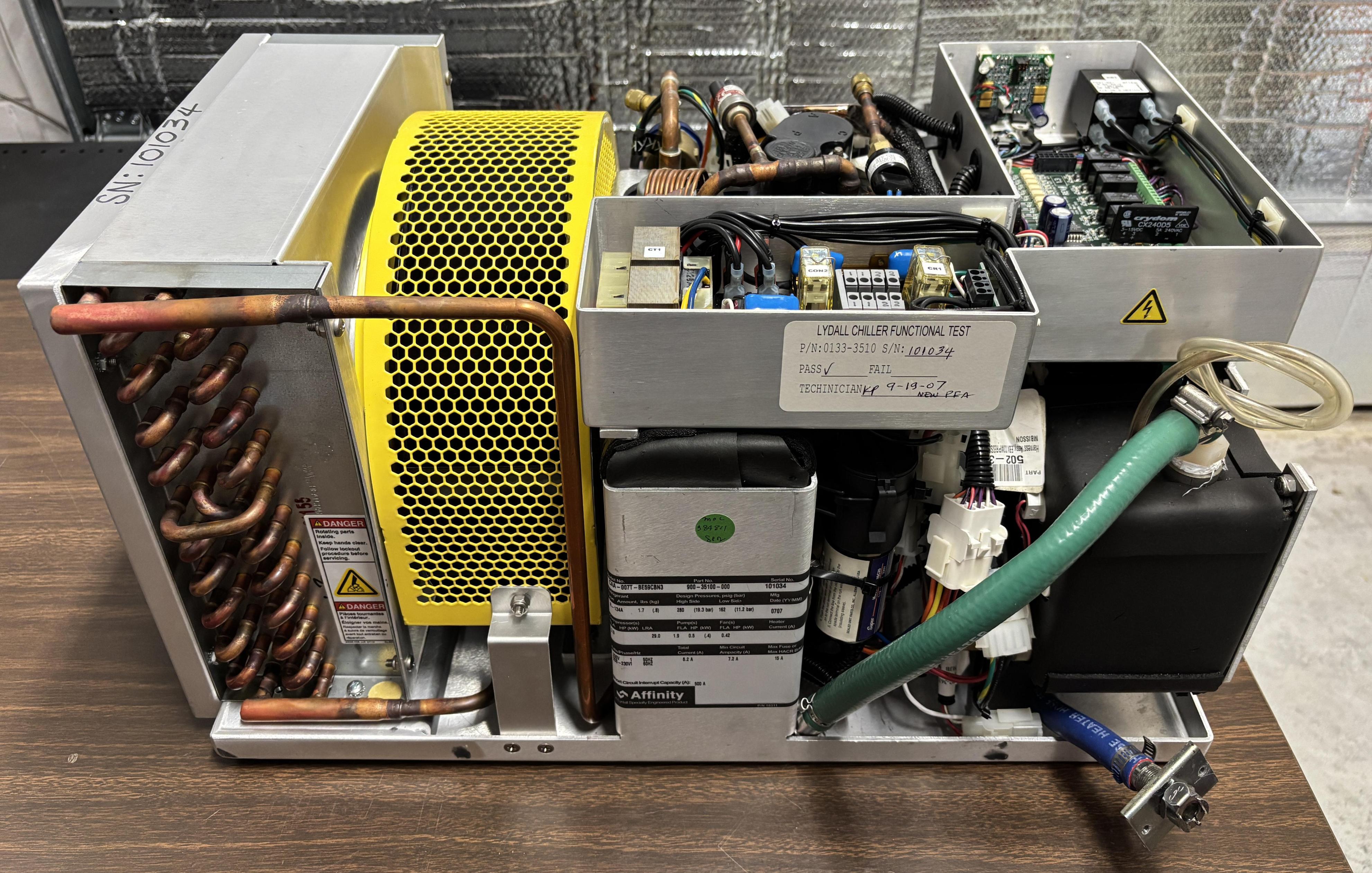
Components from left to right: Evaporator coil assembly and filter, evaporator fan (under yellow shroud), compressor and thermal expansion valve assembly, power supply and distribution, digital control board, water reservoir, and pump (under digital control board tray).
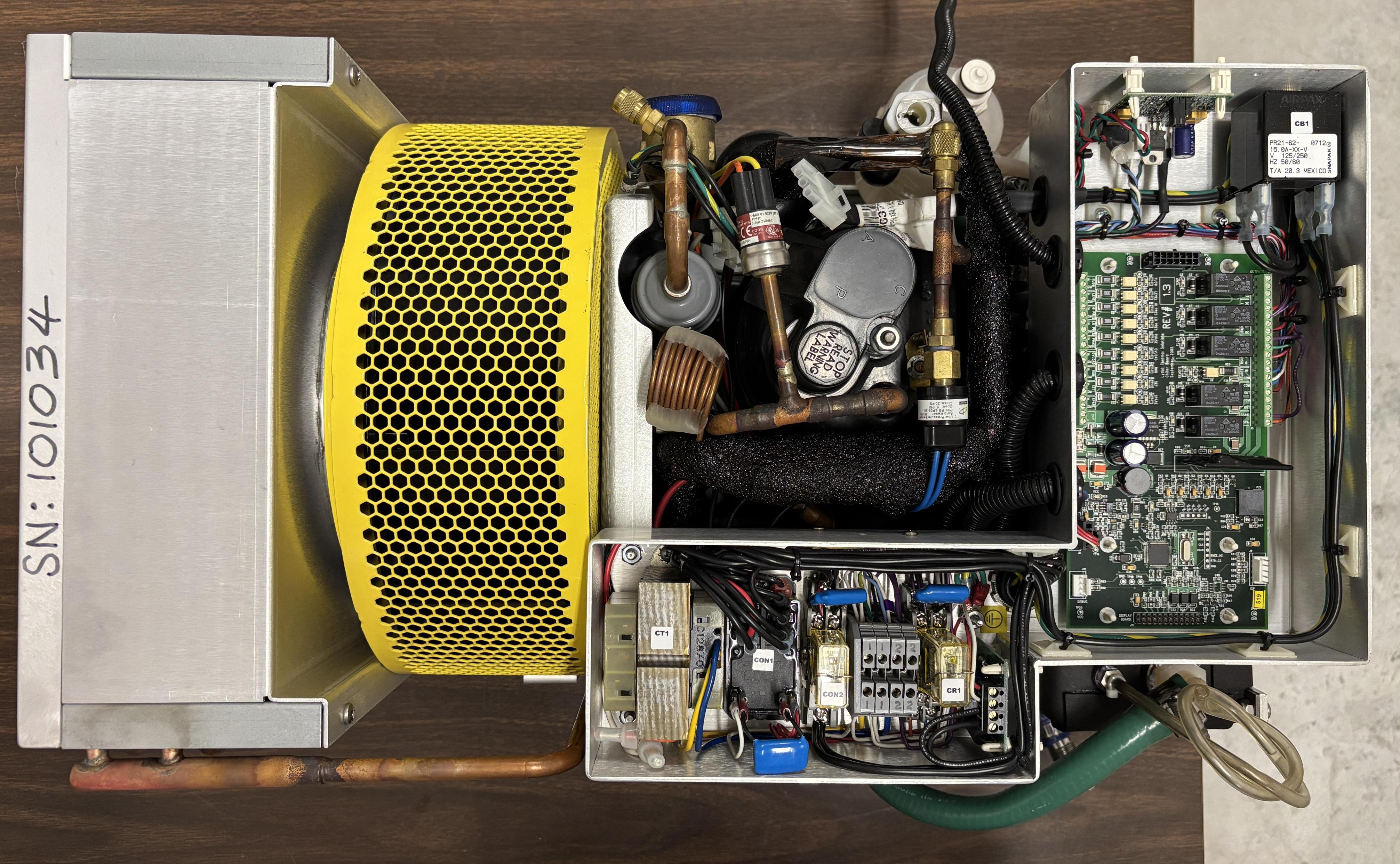
On this side, the water pump and VFD (variable frequency drive) are visible. The pump and VFD are manufactured by Fluid-o-Tech. The pump is a TMFR1 integrated pump-motor unit, and is paired with a TMFE1 VFD. The pump is a high-reliability, magnetically-driven unit where the motor has no moving parts. The chiller board controls the AC input power to the VFD but only has the ability to turn it on or off. The VFD does have the capability for external speed control and monitoring, but that is not implemented on this system. It just runs the pump at a constant, pre-programmed speed as defined by the DIP switches.
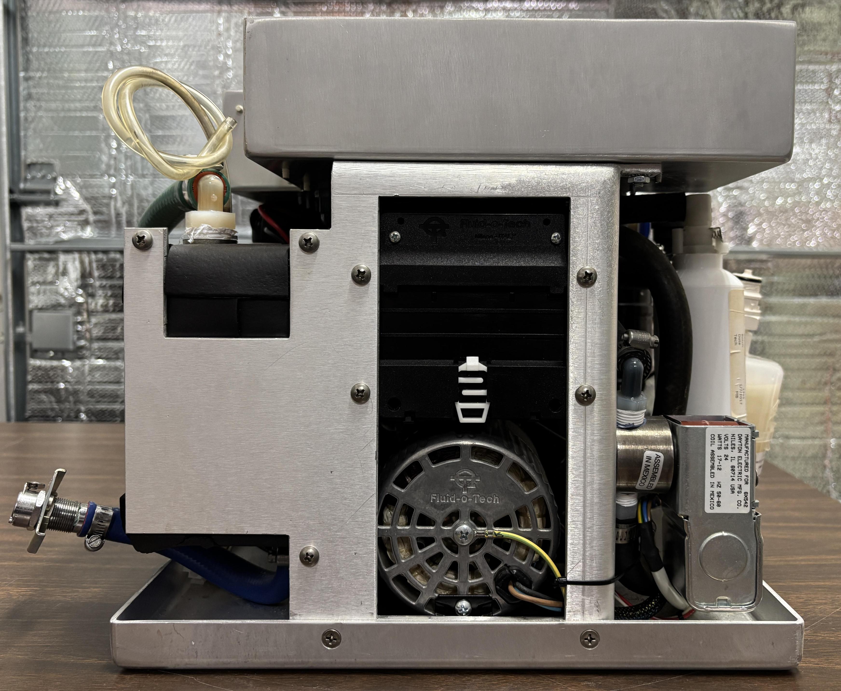
On the other side are multiple filters for the water loop which can be easily replaced using the CPC quick-disconnect fittings. Also visible is an inline flow switch which is constantly monitored by the control board. The controller will stop the pump if flow is not detected or if the reservoir level is too low, to prevent damage to the pump. Also installed are high and low pressure refrigerant sensors, which inform the controller of the status of the coolant loop. Buried deeper is an RTD (resistance temperature detector) which is used to accurately determine the temperature of the cooling water loop. Additionally, there is a heater connected to the loop, as mentioned earlier. The role of the heater is to bring the temperature up in precise adjustments if the chiller overshoots. According to the Greenlight HPS/XPS service manual, this chiller has a solenoid valve (lower left corner) that can be activated in order to allow return water to flow through a resin, de-ionizing filter cartridge in order to keep the water resistivity around 0.25 megohm-cm. This is known as D.I. polishing. Presumably, this means there is also a sensor to determine the resistivity of the water, but we have not yet identified such a sensor. Based on our observations, the SPARE input is used to activate the D.I. polishing function, so perhaps the laser system senses the resistance or just activates the function on a predetermined schedule.
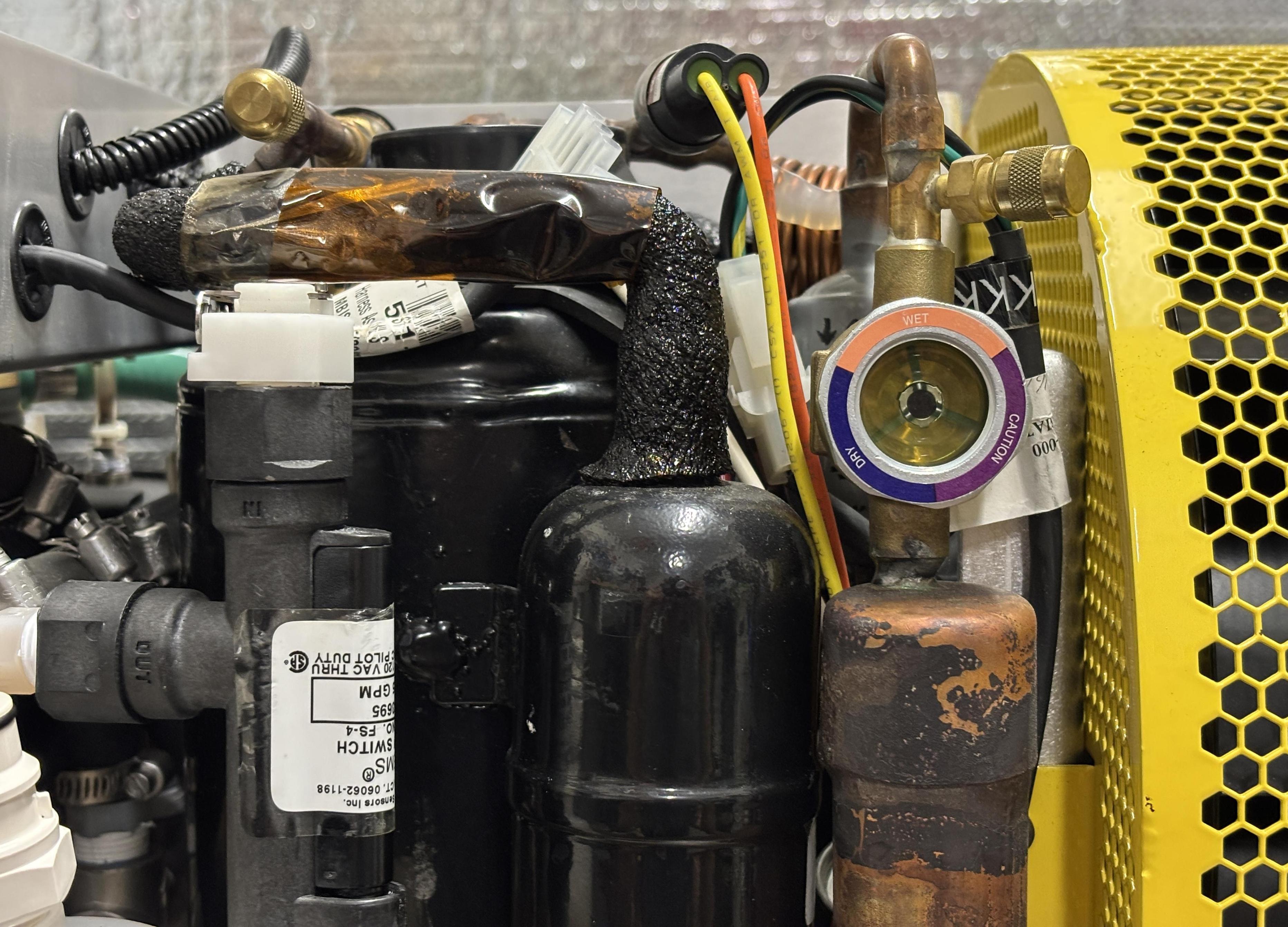
In this section, the flow switch is visible in the lower left corner. Towards the top are the capped refrigerant fill and evacuation ports on the low and high side. A pressure sensor is also visible (orange and yellow wires). A refrigerant sight glass is provided to monitor refrigerant flow and also includes a chemical moisture indicator. The indicator in this chiller appears to be purple, which means caution based on the key on the sight glass. Perhaps the refrigerant circuit has accumulated a bit of moisture. Luckily, the chiller works fine and this has not been an issue as of yet.
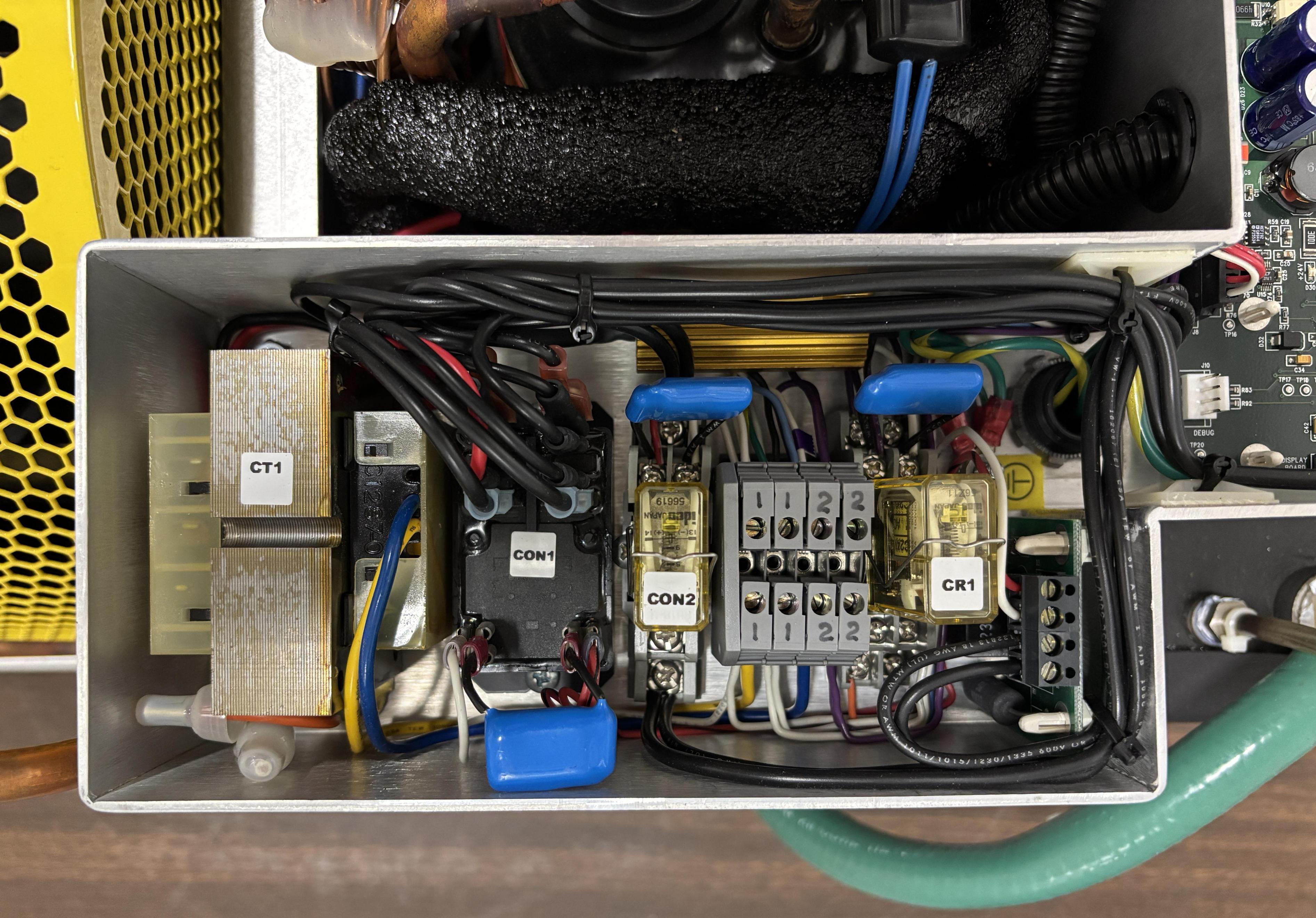
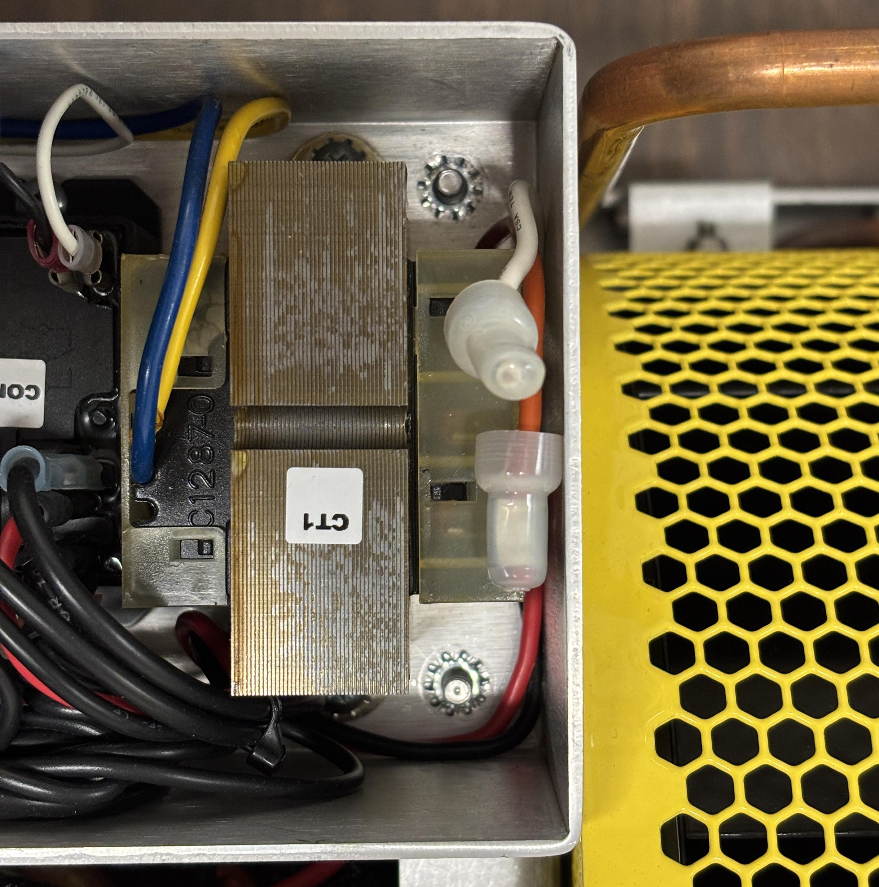
This section includes some relays and a contactor responsible for switching the high-current components such as the compressor, fan, and pump. The relays are commanded by the digital controller. The transformer labeled CT1 is the control transformer that steps down the 240 VAC input to around 24V for use by the low-voltage control electronics. This is further rectified and reduced on the digital board.
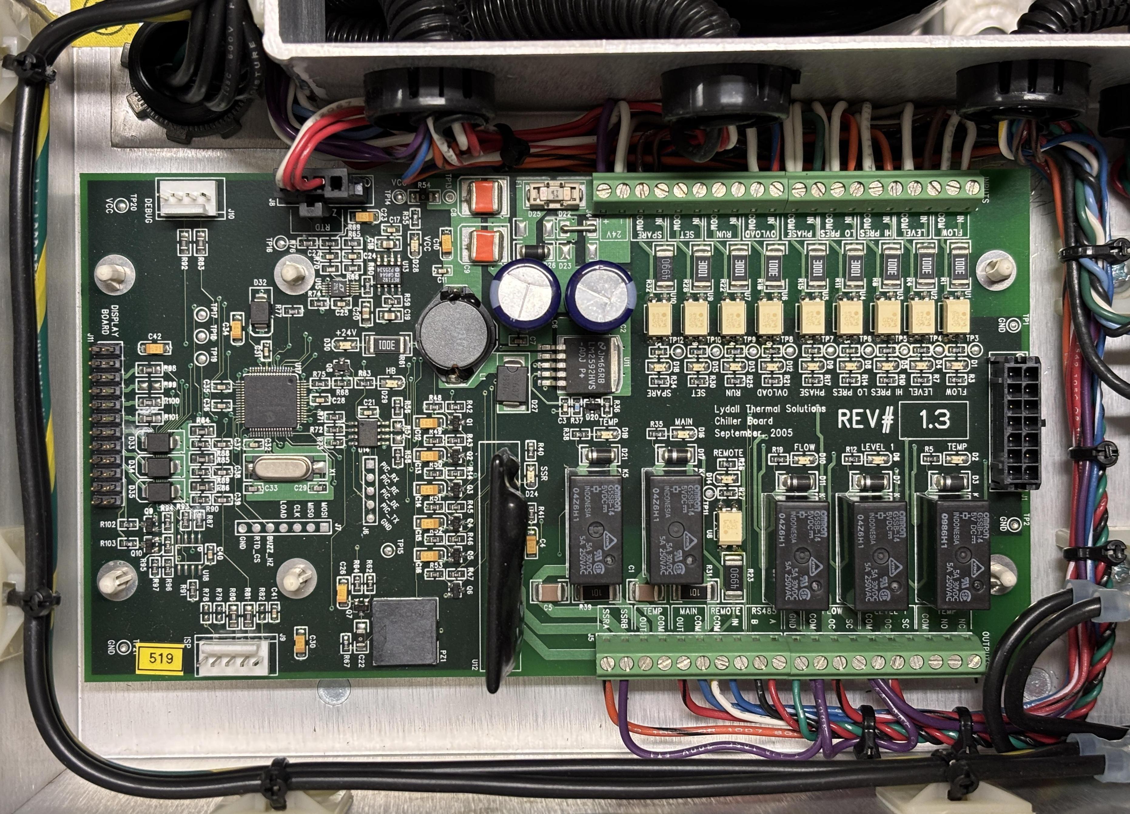
This is the Lydall Chiller Board (REV 1.3 / 2005). This serves as the chiller's full-authority digital control and monitoring system. It's based around a Microchip PIC18LF6720 8-bit MCU which constantly monitors all inputs and sensors and subsequently controls the chiller via a series of relay outputs. Once powered, the chiller is started by the REMOTE input. Supplying around 7V DC equates to a chiller run request and will start the chiller and pump. It will continue to run as long as no faults are detected and power to the REMOTE input is maintained. The status of the chiller can be monitored over RS-485 by a proprietary protocol that we decoded (more information provided further down on this page). The temperature setpoint can likely be adjusted over the RS-485 interface as well. The chiller stores the setpoint and does not require any input over RS-485 to run. It will periodically cycle the compressor on and off as required to maintain the setpoint. It also uses the small resistive heater to fine-tune the setpoint as needed. The logic contained within the firmware of this board is capable of protecting the system from damage in the event of faults such as insufficient flow, loop temperature limit violations, low water reservoir level, and pump overload. It will also protect the system from short-cycling of the compressor. When we first worked with this chiller, it powered on briefly and then shut down. It refused to run for any subsequent attempts. After checking the coolant reservoir and status LEDs, we determined that it was low on water. Adding water and then restarting it solved this problem immediately and allowed the chiller to run without issues.
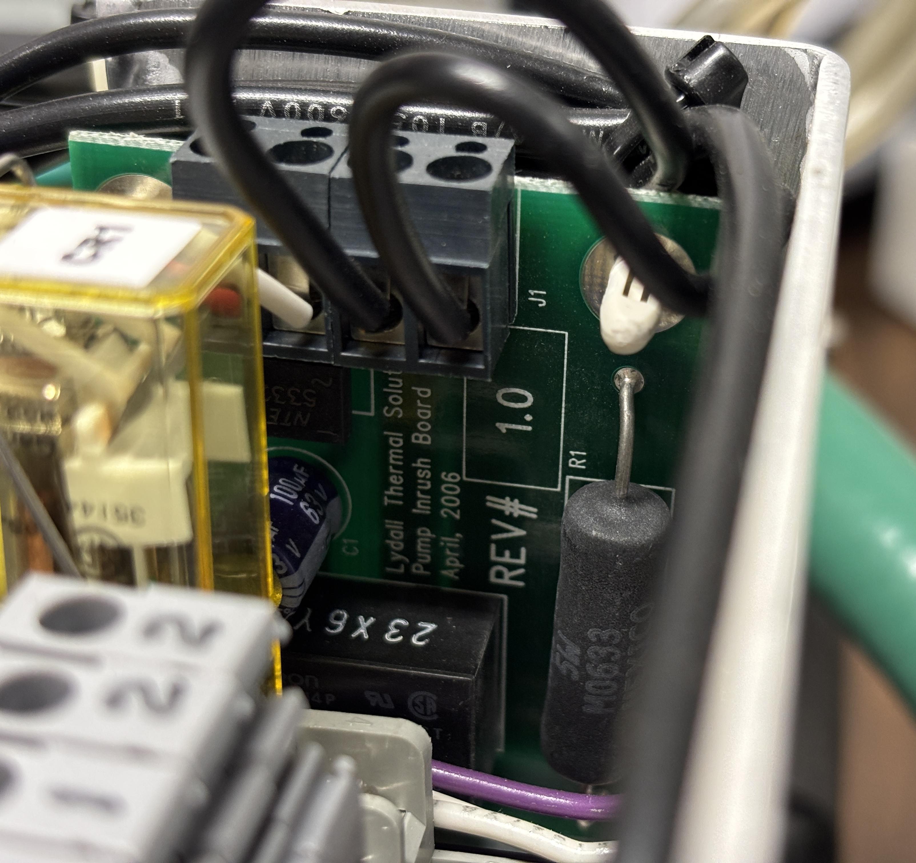
This is a small additional board mounted to the side of the electronics tray. It's labeled "pump inrush board" and appears to serve that exact function. This helps prevent disruptions to the electronics and other components from the large inrush current when the pump starts.
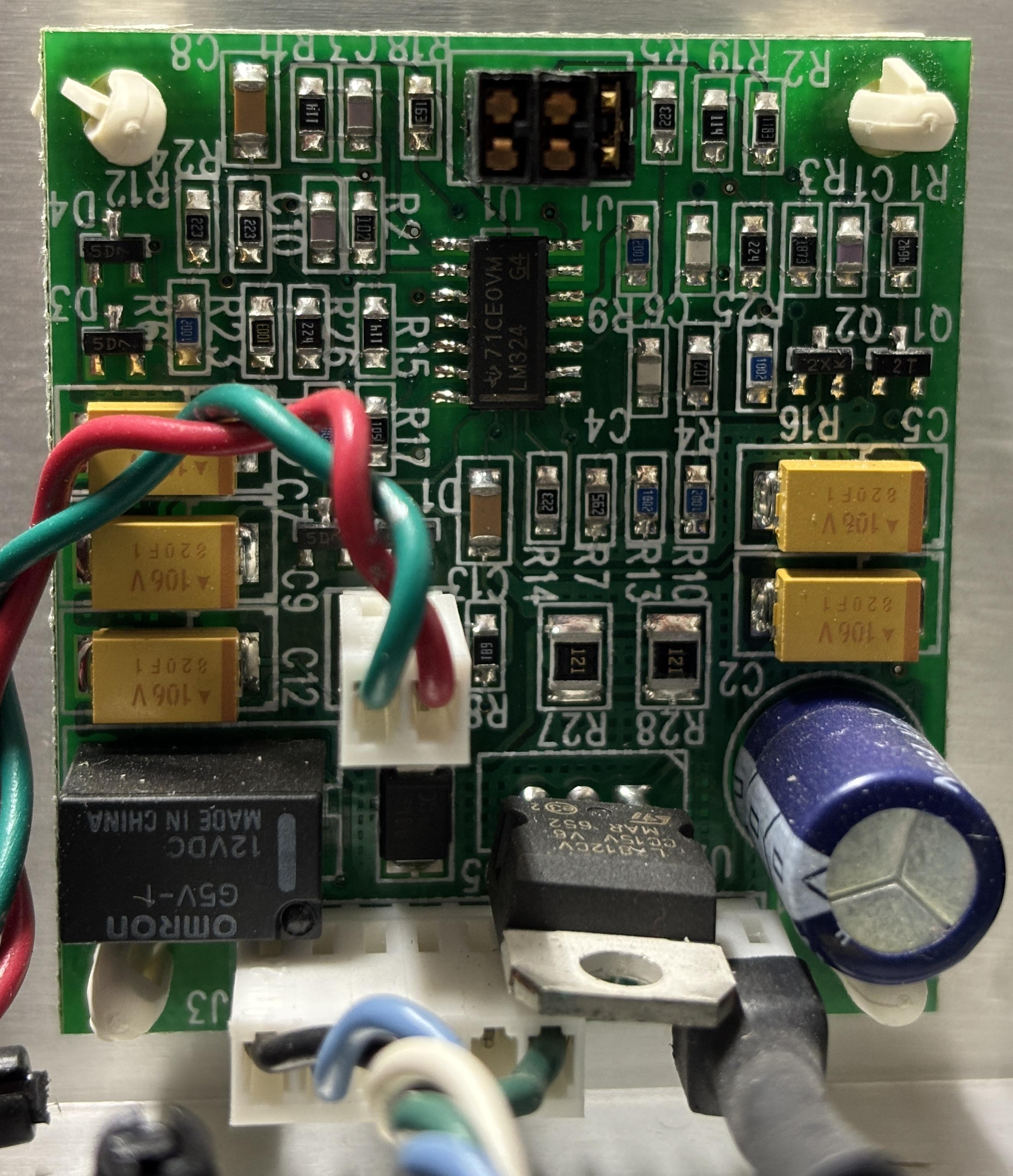
We're not entirely sure of the purpose of this board, but it includes a relay, connections to the main chiller board, LM324 operational amplifier, voltage regulator, and the connection for the status LED. It may just be a simple status monitoring board. A bi-color led is connected to a 2-pin header on this board and can be used to quickly tell whether the system is powered on and if the compressor is currently running. Green indicates compressor not running, but loop temperature within range. Red indicates loop temperature not within range.
The electronics tray can be removed from the top of the chiller after undoing four nuts with lock washers, two of which are directly beside the control transformer. The usage of electrical connectors allows the chiller electronics to be swapped out without having to disassemble the entire unit.
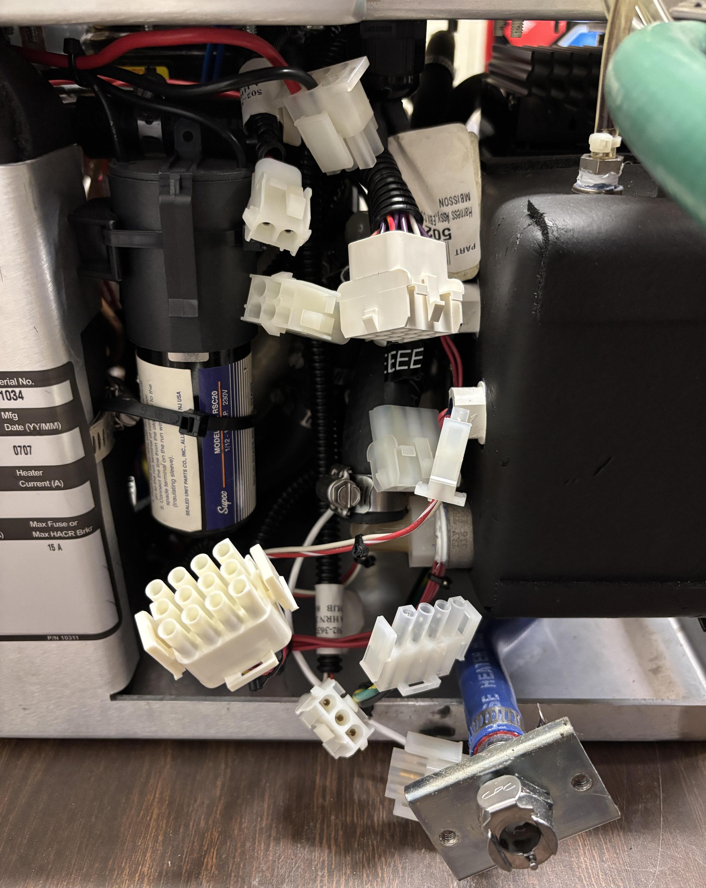
Here are the majority of the connections from the control and power distribution tray that lead to all the individual sensors and devices within the chiller. The drain line (blue hose with silver CPC fitting) is also visible. The usage of quick-disconnect fittings and electrical plugs makes this a very serviceable unit.
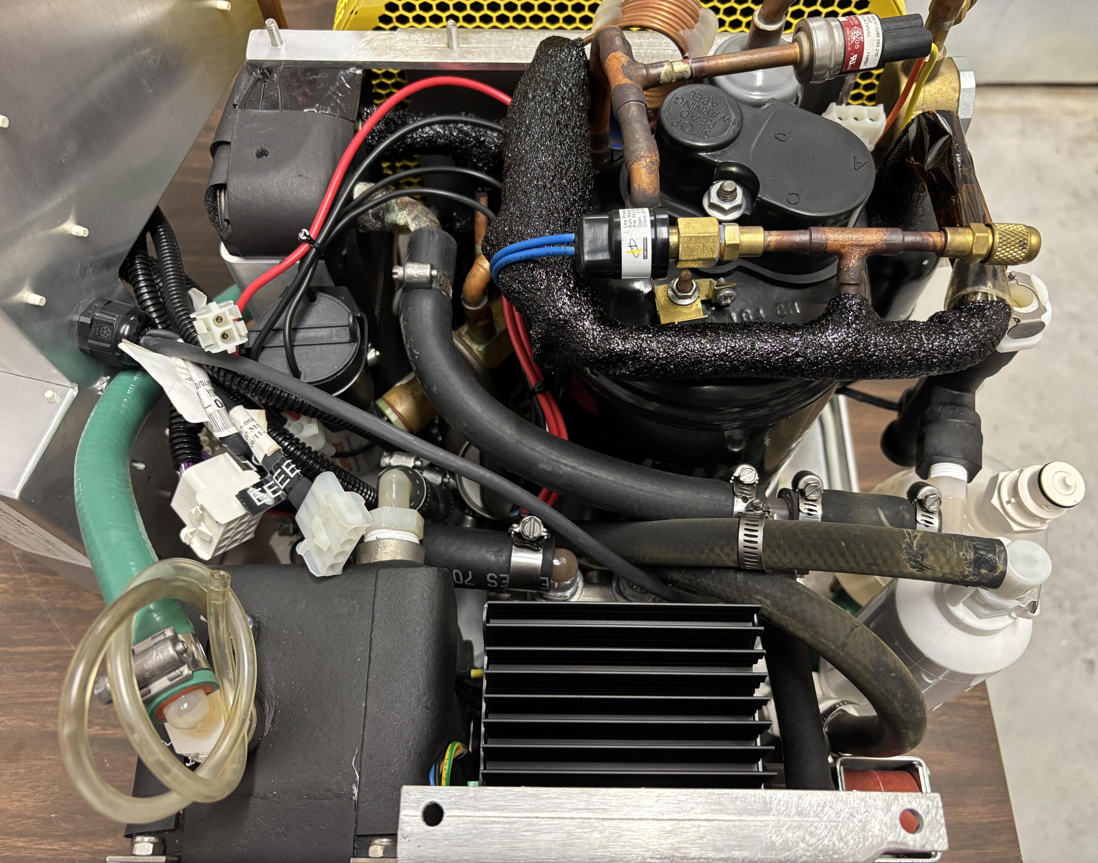
Here is a view of the top of the chiller with the control electronics tray removed and placed off to the side. The water reservoir is visible on the left with a green hose coming from the top. This is for the external fill port. To the right of the reservoir is the pump and VFD. Common chiller components such as the compressor and coolant lines are visible above the reservoir and pump. Specific sections of the copper coolant lines are wrapped in a sticky insulating material to prevent condensation buildup.
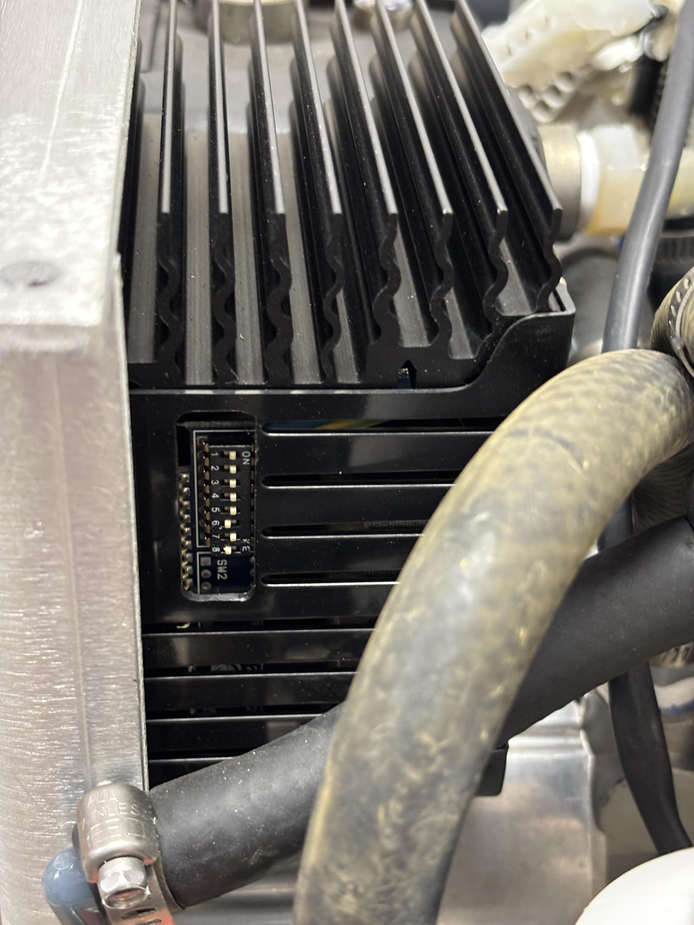
This side view of the Fluid-O-Tech TMFE1 VFD shows the fins for heat dissipation and DIP switches for configuration. As presently configured, this VFD will spin the pump at around 1750-2000 RPM without any external control or monitoring. We are basing this off the TMFR2/TMFE2 manual as we were unable to locate the exact manual for this pump/driver combination. Assuming the DIP switch configuration is the same across models, it should be around 1750-2000 RPM.
RS-485 Communication
Communicating with this chiller was a learning experience. Luckily, the system designed to control and monitor it (AMS Greenlight HPS) was in working condition, so we captured and analyzed the RS-485 communication between the laser control system and the chiller control board. From startup to shutdown, the laser polls the chiller board but does not attempt to write or adjust any parameters. It only reads a variety of status registers. The chiller board is a slave and will not transmit any data unless polled by a master. We wrote a Python program that monitors the chiller over RS-485 using an RS-485 to USB adapter. The program can operate in passive mode to listen in on the conversation between the laser controller and the chiller board. The program can also operate in active mode to poll a standalone chiller being operated outside of the context of the original laser system. We don't recommend polling the chiller while the laser controller is also polling it, as this could cause issues.
Important: bias resistors are needed to pull the RS-485 A and B channels up and down respectively. We had success using 1,000 ohm resistors to pull RS-485 A up to ~3.6V DC and B down to signal ground. Monitoring the chiller without the laser control board connected (using the script in active mode) may not work properly until the bus is properly biased. Based on our testing, termination resistors are not necessary.
A screenshot of the chiller live monitoring program is provided below. It's very basic and only intended to display the essentials.
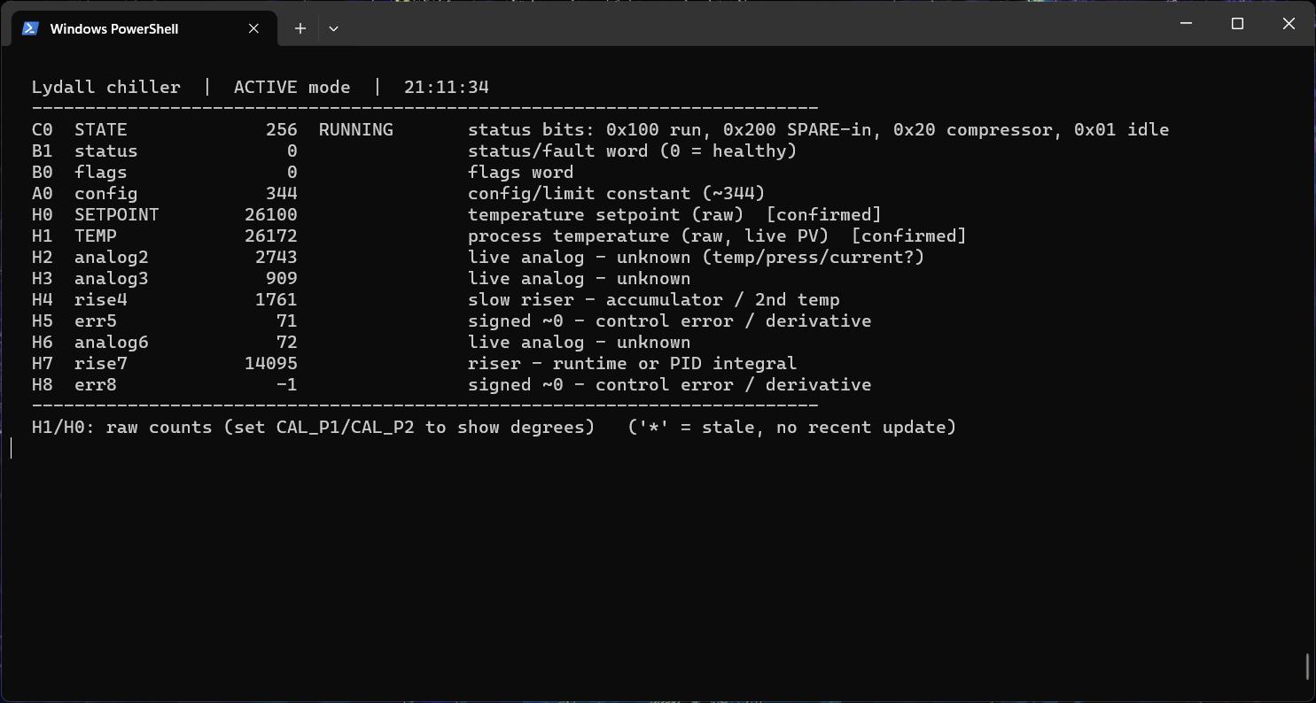
The serial parameters are: 38400 baud, 8 data bits, no parity, 1 stop bit. Half-duplex RS-485. Below is the poll/reply frame syntax. Every byte in the frame, including the checksum, sums to 0x00 mod 256. To validate any received frame, sum all bytes. The low byte must be 00.
- poll: 40 42 30 [len] [ASCII COMMAND] [checksum]
- reply: 06 [len] [big-endian data] [checksum]
Below is an abbreviated list of commands with the checksums included. These are register requests, and do not change any chiller parameters or attempt to control the device. These can be sent directly to the Lydall chiller over RS-485 to verify functionality and ensure proper communication.
| Hex Data (send) | Register | Response |
|---|---|---|
| 40 42 30 02 43 30 D9 | C0 | Status bitfield — run / compressor / SPARE / lockout |
| 40 42 30 02 42 31 D9 | B1 | Status / fault word (0 = healthy) |
| 40 42 30 02 41 30 DB | A0 | Config / limit constant (unknown) |
| 40 42 30 02 48 30 D4 | H0 | Temperature setpoint (raw counts) |
| 40 42 30 02 48 31 D3 | H1 | Process temperature (raw counts, live PV) |
| 40 42 30 02 48 32 D2 | H2 | Live analog data (unknown) |
| 40 42 30 02 48 33 D1 | H3 | Live analog data (unknown) |
| 40 42 30 01 49 04 | I | 16-byte device ID / config block (static) |
| 40 42 30 01 5A F3 | Z | Scan-boundary keepalive |
Status LEDs and I/O
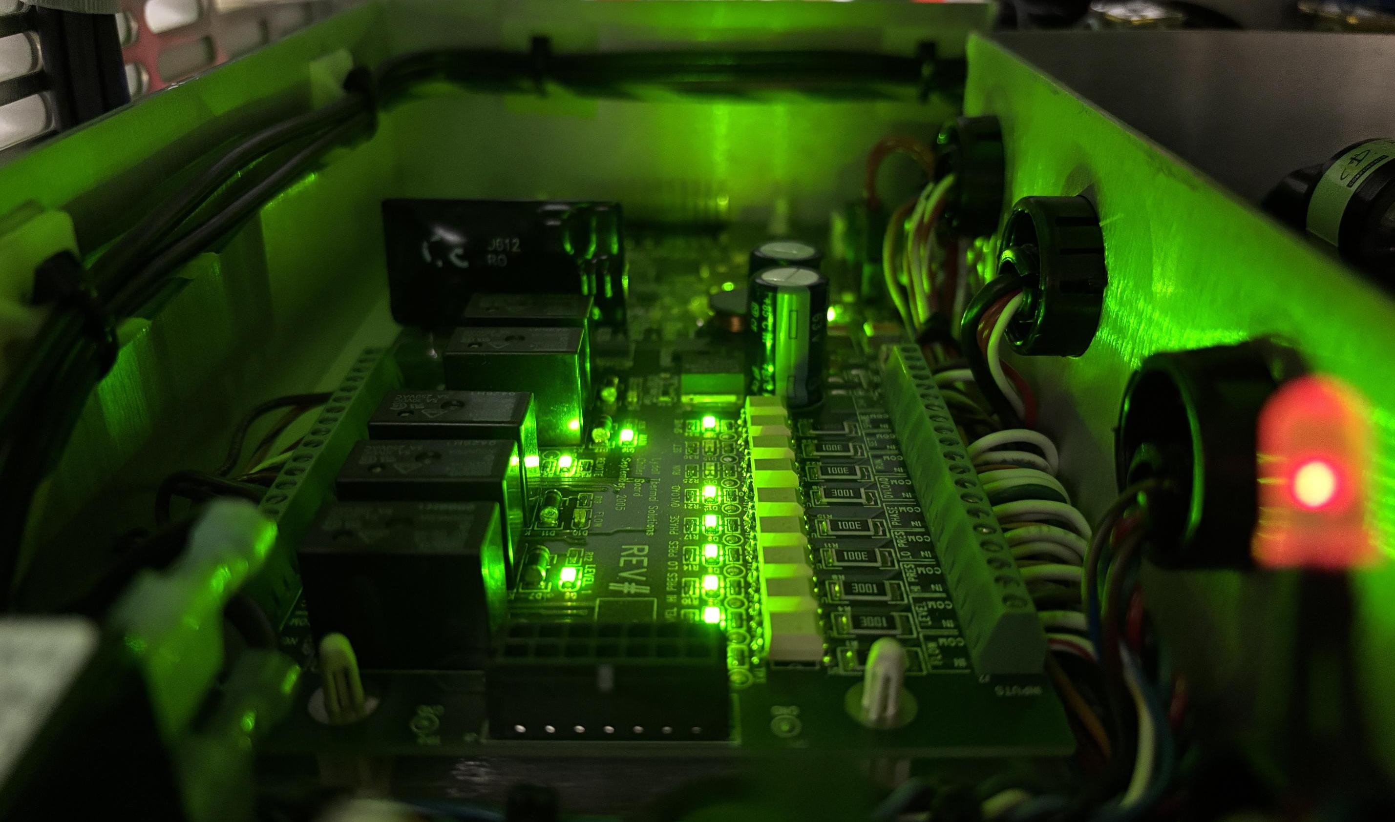
The chiller board has a variety of green status LEDs that are somewhat useful for monitoring the chiller manually. We say somewhat because the silkscreen labels are ambiguous for some of the LEDs. Monitoring the LED behavior as the chiller starts up, runs, and cycles, does provide useful insight, but still leaves some unanswered questions. Here is a table of the LEDs along with a description based on our observations and reverse engineering efforts.
| LED Silkscreen Marking | I/O | Description |
|---|---|---|
| +24V | - | 24V power OK |
| VCC | - | Processor low-voltage DC power OK |
| HB | - | Processor heartbeat (1 Hz) |
| SSR | O | Solid state relay status (heater control, periodically activates during operation to maintain setpoint) |
| TEMP (D19) | O | Potentially temperature alarm, never active during normal operation |
| MAIN | O | Main chiller electronics status (fan, etc. always illuminated while chiller is running) |
| REMOTE | I | Remote run input status (illuminated when remote run is active) |
| FLOW (D10) | O | Flow sensor status (ambiguous, periodically cycles on and off, potentially related to SPARE) |
| LEVEL 1 | O | Ambiguous (illuminated when compressor is running, off when setpoint reached) |
| TEMP (D2) | O | Unknown |
| SPARE | I | SPARE input status, laser controller periodically drives the input (likely call for de-ionize filter polishing) |
| SET | I | Never active during normal operation, potentially used to enable changing setpoint |
| RUN | I | Unknown, never active during normal operation |
| OVLOAD | I | Pump overload, illuminated = normal |
| PHASE | I | AC phase indicator, illuminated = normal |
| LO PRES | I | Low pressure switch status, illuminated = normal |
| HI PRES | I | High pressure switch status, illuminated = normal |
| LEVEL | I | Level sensor, illuminated during normal operation |
| FLOW | I | Flow sensor/switch status, illuminated during normal operation |
Extracting the code from the PIC microcontroller
We took this reverse engineering exercise a step further by obtaining a PICkit 3 to connect to the chiller board's ISP connector and extract the program code from the chip. The 5-pin connector labeled J9 is a dedicated ISP connector, conveniently populated and even labeled! Manually probing these connections and tracing them back to pins on the PIC MCU confirmed that it had all the necessary connections for ISP (in-system programming). The pin-out for the connector has been provided below. Pins are ordered from left to right, with the locking tab on the bottom.
- 1 - VDD
- 2 - PGD
- 3 - PGC
- 4 - MCLR/VPP
- 5 - VSS
We were banking on the code protection bits not being set. When set, this function prevents reading of firmware and EEPROM code with debugging tools, as a method to prevent reverse engineering and protect intellectual property. If a chip has these protections enabled, you can only disable them by erasing the chip (useless when reverse engineering) or by following microcontroller exploit techniques. Travis Goodspeed wrote a great book called "Microcontroller Exploits" which covers this topic in detail. Luckily, the only protected section of the PIC microcontroller on this board was the boot block. It's not completely clear why this small (and arguably insignificant) section is protected, while other sections such as the main program memory are not. However, we're not complaining! This specific PIC-18 has 5 sections of program memory, the boot block and blocks 0-3. As mentioned, the boot block was protected on this chip, while program memory blocks 0-3 were unprotected. This allowed us to easily dump all program memory from blocks 0-3. The boot block is so small and only contains boot-related code and vectors, so it's not a big deal for that to be omitted. If you'd like to examine the program code for yourself, you can download the raw hex file at the link below. Keep in mind the first section (0x0000-0x01FF) is blank due to the boot block code protection.
Using a combination of AI-based decompilation tools and Ghidra, we ripped apart the program stored on the PIC. The most notable finding is the presence of a second serial interface, specifically for diagnostic purposes. According to the decompilation, this interface prints human-readable ASCII text and can be used to view the chiller's status, read sensors and inputs, and actuate relays. It appears to use the same 38400 8N1 baud and serial parameters as the RS-485 interface. The following functions are listed on the top-level menu of the diagnostic interface: Test Relay Outputs, Test Opto Inputs, Read RTD Input, Test Buzzer, Test SSR Output, Cal RTD Input, Load Default PID, Test FRAM, Current Test, Remote Input DB/Filt Test, Quit. We presume that this is the purpose of the 4-pin header labeled J10 / DEBUG. We'll probe this header and update this page next time we remove the chiller from the rest of the system.
Program decompilation also showed us that the cooling loop temperature is sensed by an RTD (resistance temperature detector) and digitized by an LTC2422, which is located near the RTD connector on the chiller board. The formula for this measurement is R = (104857600/raw) - 100. This is also how we learned about the PID-controlled heater, driven by the SSR/TEMP connections on the board. This helps to precisely maintain the setpoint as the chiller can heat the loop in addition to cooling it. Additionally, we used this information to better correlate the inputs and LEDs to their true functions. Lastly, configuration data such as calibration values and PID loop gains are stored in a separate external FRAM chip located adjacent to the PIC microcontroller. We may try and read the data out of that FRAM at some point in the future when we probe the DEBUG interface.
Below are some useful resources for learning about chillers in general. There is no public documentation for this model of chiller so we included as much relevant information as possible, but most applies to different variations/models. Lastly, the Python program for monitoring this chiller over RS-485 can be downloaded at the link below.
- Lydall Live Monitor Python Program
- Laserscope Greenlight XPS Basic Service Manual
- LG - How Does a (HVAC) Chiller Work
- Applied Membranes - Some information about D.I. polishing filters
- Fluid-O-Tech Manual for a similar pump and driver combination (TMFE2)
- Lydall Affinity Custom Chiller User Manual (different model)