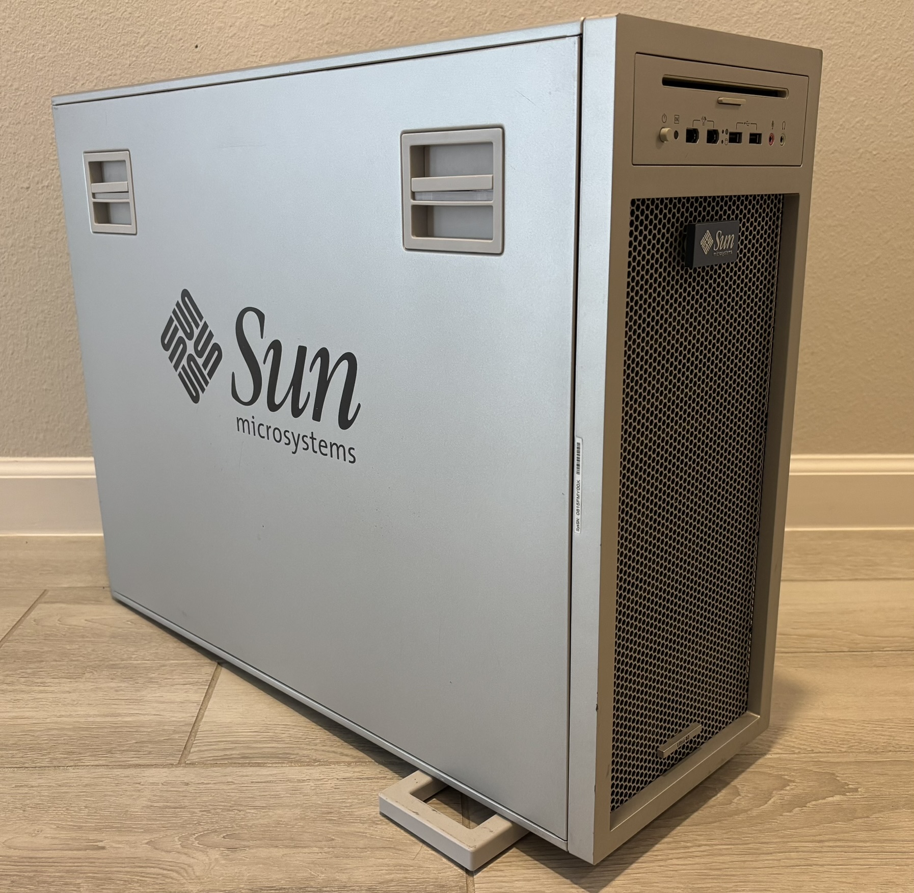
The Ultra 40 M2 is a commercial desktop computer manufactured by Sun Microsystems around 2007. It's an x86 PC and does not feature a SPARC processor like many of their other products. This system was intended to be a high performance and reliable workstation capable of running common operating systems such as Microsoft Windows XP, Red Hat, and Solaris. The system normally shipped with Solaris 10 installed. The processor architecture is 64-bit making a also capable of running the 64-bit version of Windows XP. We even got the system to run Windows 7 and Windows 10. With an SSD, it's surprisingly usable for basic computing tasks despite the hardware being outdated. Below are some basic specifications:
- CPU: AMD Opteron dual-core (socket F/1207)
- RAM: 8 slots (4 per processor) of DDR2-667 ECC memory, maximum memory capacity of 32 GB
- Storage: Up to 8 SATA drives (SAS drives supported with optional PCIe SAS controller)
- Factory GPU: NVIDIA Quadro FX 1500
- Power Supply: 1000W PSU
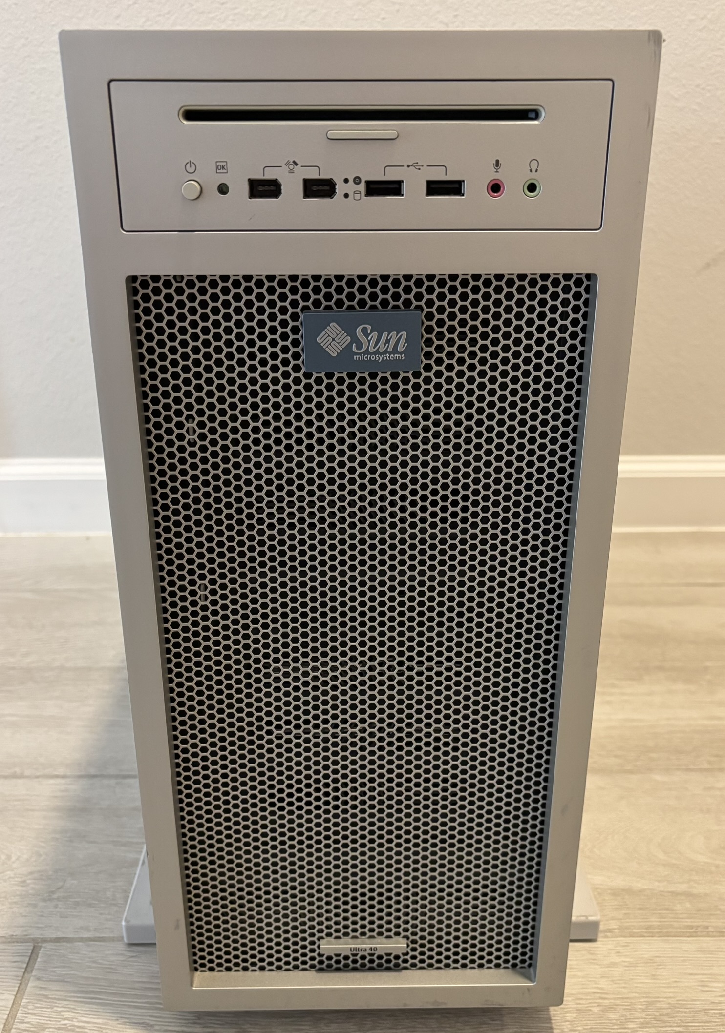
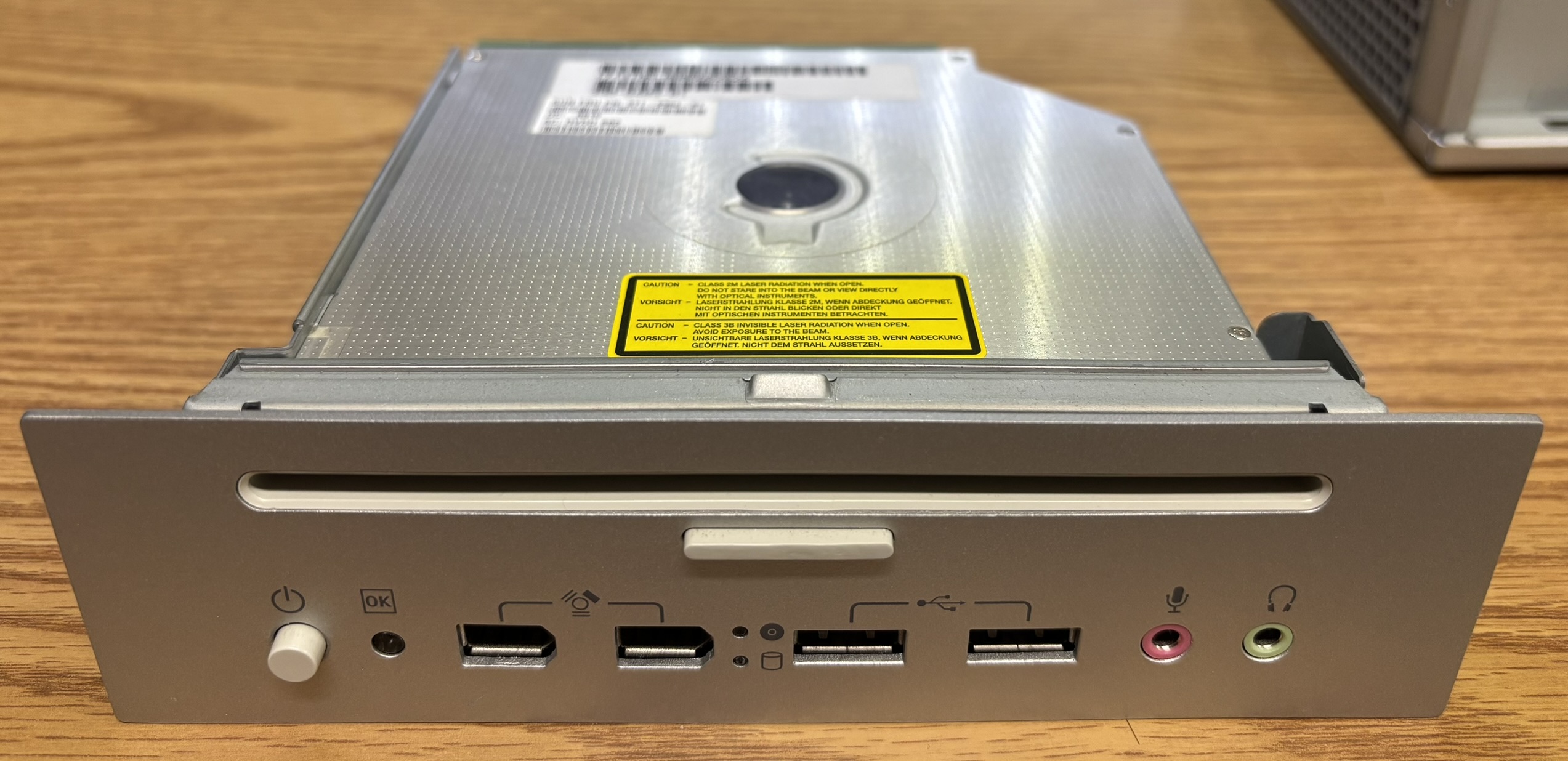
The front panel of the Ultra 40 M2 is quite possibly our favorite design for a desktop computer workstation. It is made of high quality metal and plastic and is sleek and modern, yet utilitarian. This is the ideal blend of both form and function. On the top is a slot-loading optical disc drive with an eject button. On the left is the power button followed by an OK LED. The OK LED illuminates a brilliant green when the system is powered on, and presumably not experiencing any hardware issues. Next are two FireWire 400 ports, an interesting predecessor to USB, commonly found on Apple Mac computers. Next are the optical drive and hard drive activity LEDs. After that are two USB 2.0 ports, finally followed by the microphone and headphone jacks.
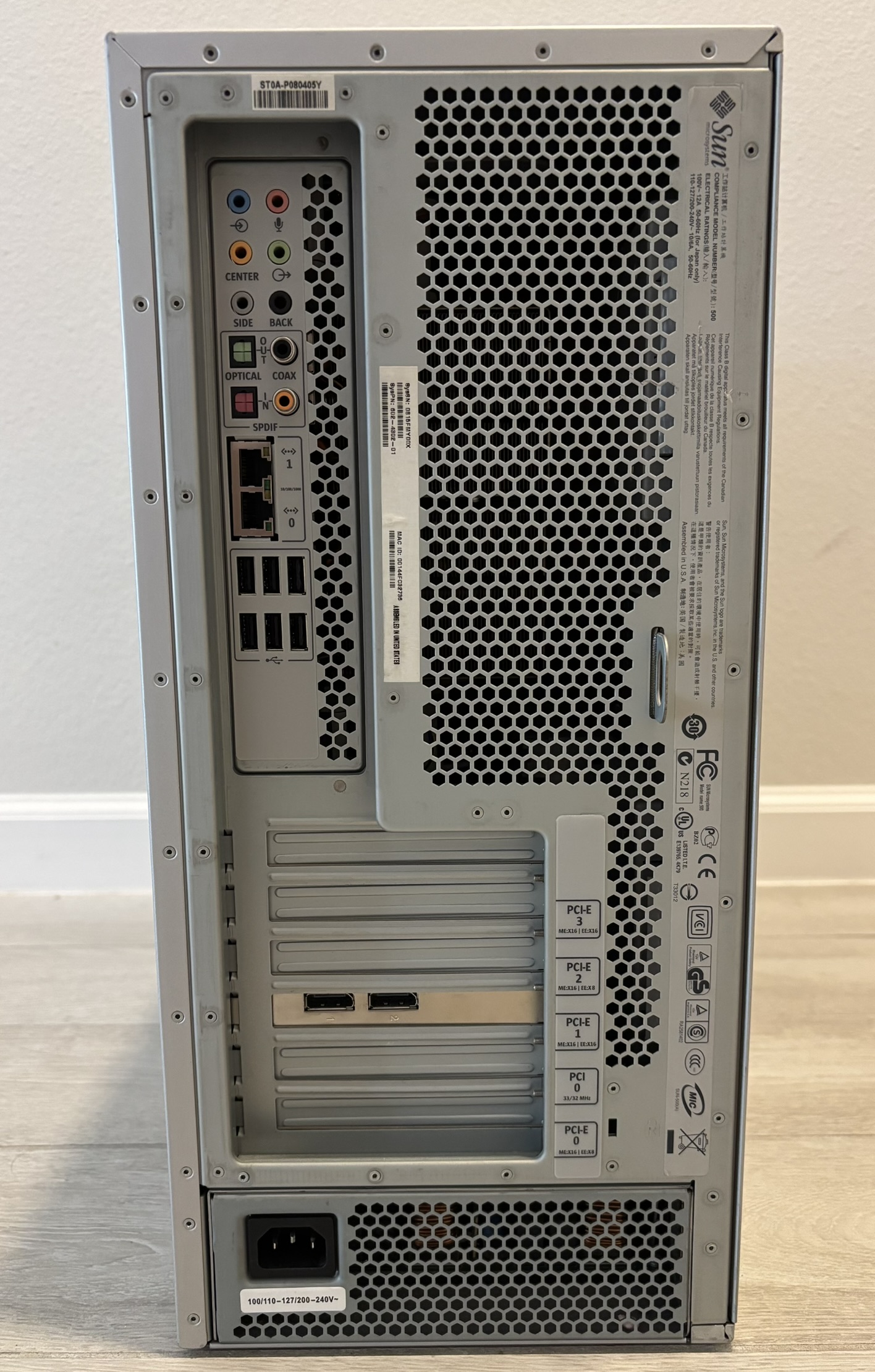
There is a large selection of connections on the back. The system features a wide selection of digital, analog, and surround audio connections. It also has two gigabit Ethernet interfaces, and 6 USB 2.0 plugs. There are 4 PCI-Express slots, and one standard PCI slot. One PCI-E slot is occupied by the graphics card. It's worth noting that the stickers next to the PCI slots indicate the slot number as well as the lane capacity (x8, x16, etc.) Minor details like this are why we enjoy working with these types of computers instead of more modern systems. Back then, they actually wanted you to service the system! The power supply ejects from the rear out the back of the system when released from the inside of the case.
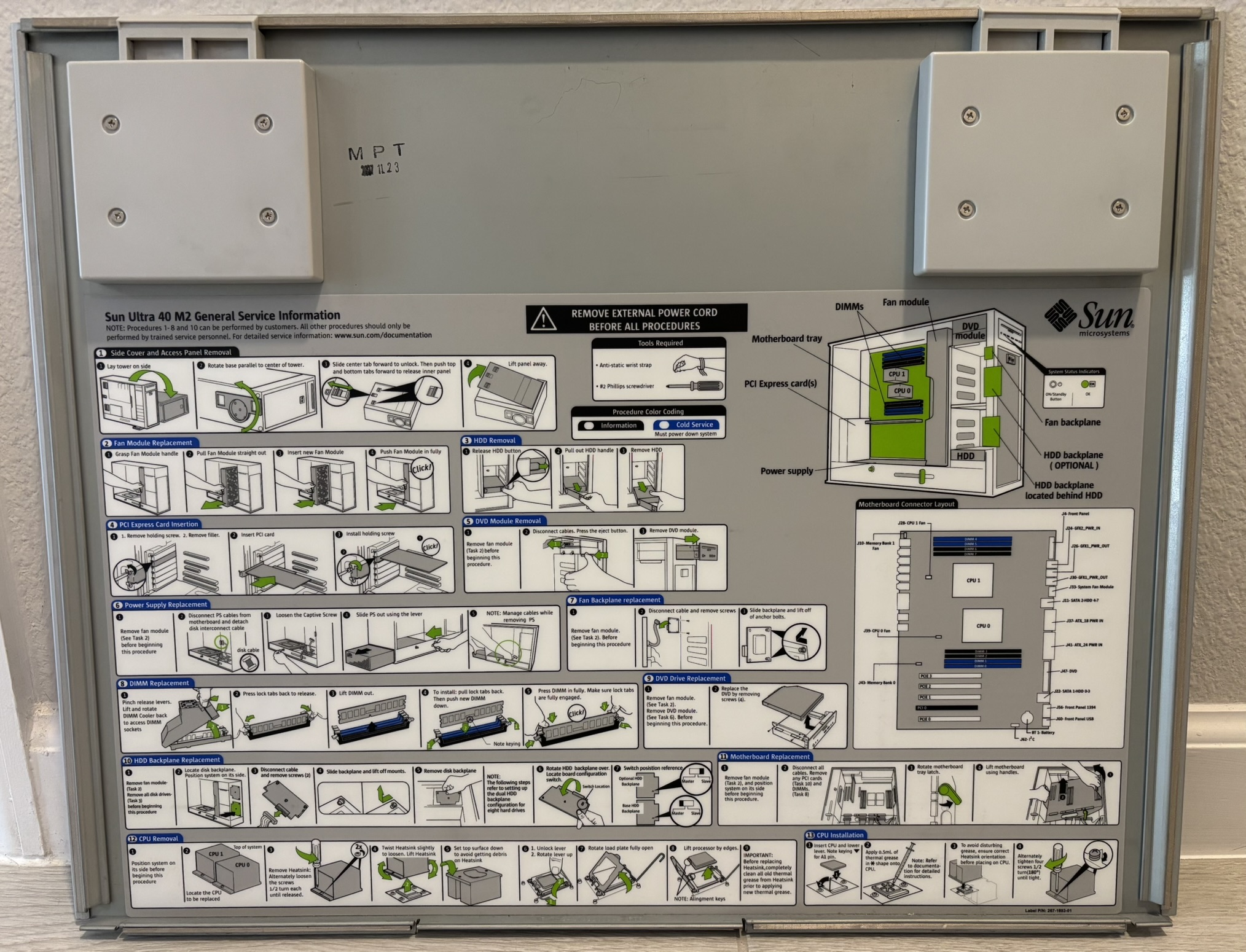
The inside of the side panel has an excellent quick reference guide for replacing many components. It also contains useful information such as component and connector placement on the motherboard. This is often seen on enterprise servers, but is less common on desktop computers. Sun Microsystems actually wanted you to be successful in fixing the system yourself!
Removing the metal side panel reveals the inside of the computer, protected by a plexiglass panel. The system can be operated safely with the metal side cover removed as long as this plexiglass panel is installed. A feature like this is exceptionally rare for a computer. It's not just an airflow guide, as it would not need to be transparent. Perhaps Sun Microsystems was so proud of their product that they intended it to be used and displayed with the opaque metal cover removed. You can see a good portion of the motherboard and internal components when the plexiglass panel is installed. Sliding the latch over to the unlocked position and squeezing the two plastic handles allows the plexiglass panel to be removed.
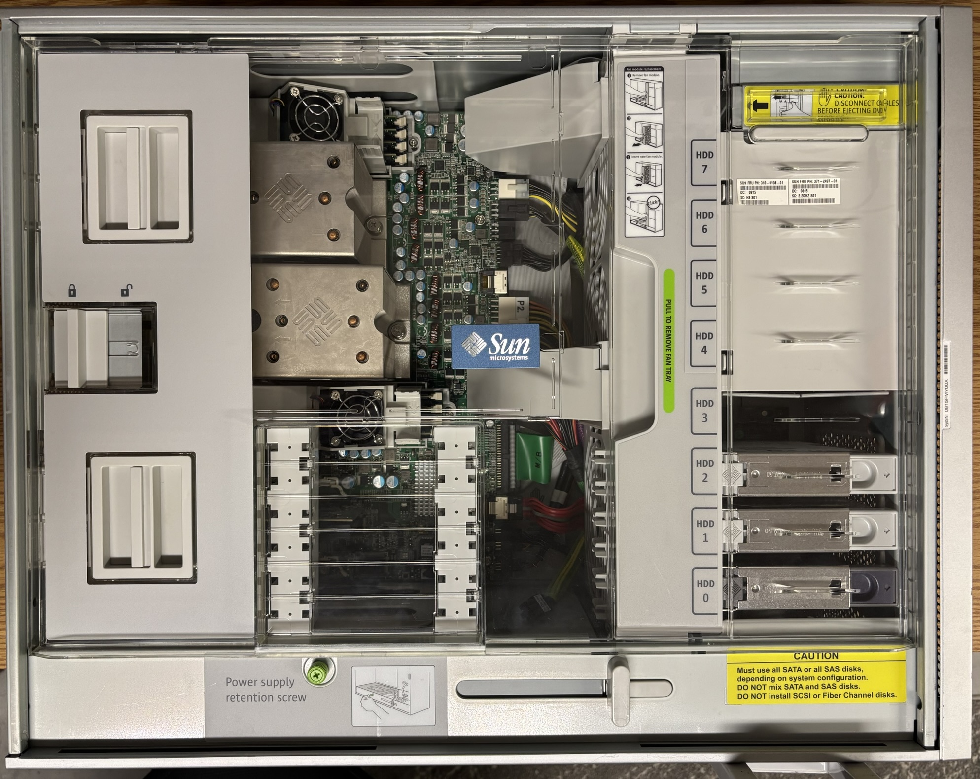
There is a large plastic fan tray mounted near the center of the chassis. It has 3 large fans that are quite loud at full speed, but normally run at a quite idle speed during normal operation. The fan tray is easily removable by pilling it straight out. The fan power connector automatically mates to a socket mounted to the casing behind it.
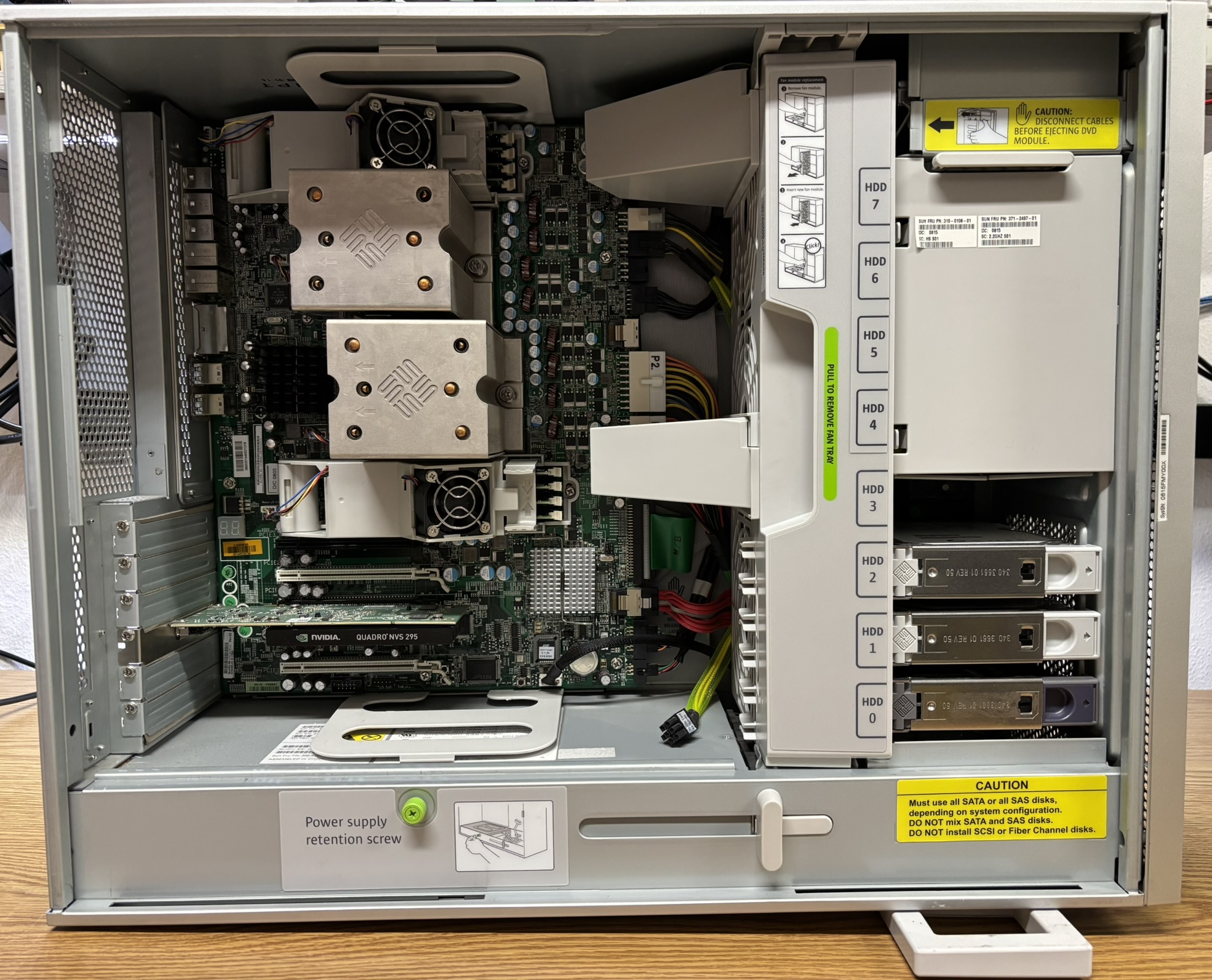
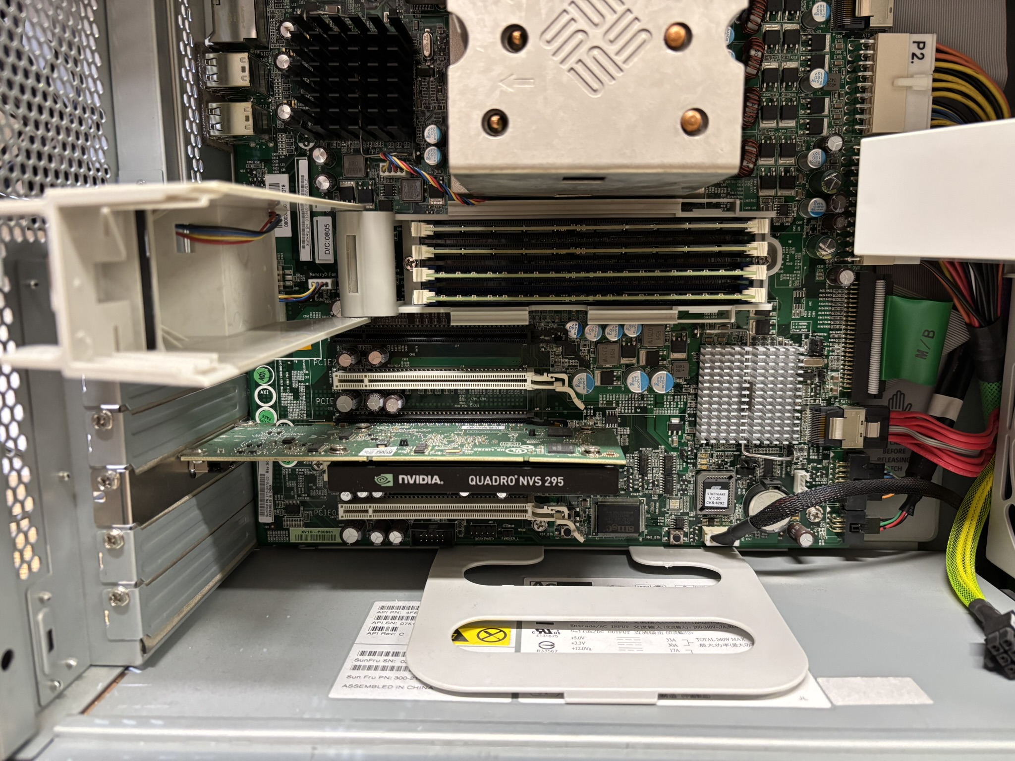
Each bank of 4 memory modules has a door with a fan that provides extra airflow for the modules while allowing easy access to remove and install them. We installed an NVIDIA Quadro NVS 295 graphics card in the system, but that is not what it would have originally shipped with.
With the fan tray removed, more of the power supply and front panel connections are visible. The motherboard is removable as an entire unit once all components and cables are removed. The handles on the top and bottom attach to the motherboard backplate and allow it to be slid towards the front of the case once a retention latch is released. All motherboard and internal connections are clearly labeled and easily accessible. Each CPU heatsink is attached by two screws and contains an embedded cooling fan. The power supply slides out the back of the chassis once the cables are disconnected and retention screw is removed.
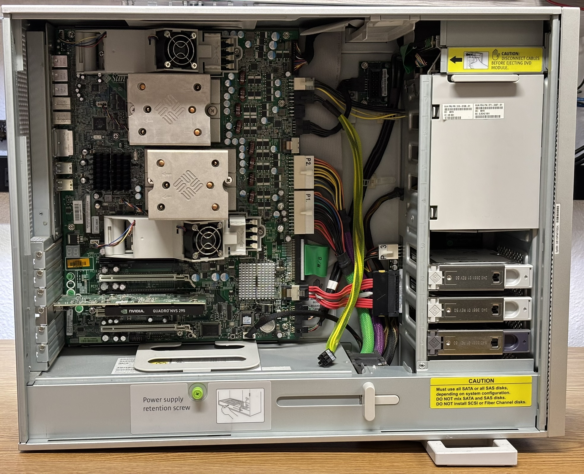
One of our favorite features of this computer is the POST (power on self test) code display on the motherboard. A two-digit seven segment LED display indicates the current POST code during startup. This is extremely useful when diagnosing POST failures and hardware issues. The indicated POST code can be looked up in the service manual to determine where the system is getting stuck during the POST process. For example, a code of 00 indicates a successful POST and that control has been handed off to the operating system. A code of 2E is displayed while the system tests the first 512K of RAM, and a code of 45 means the system is initializing all motherboard devices. This is a superior predecessor to POST beep codes or LED blink patterns common on modern computers.
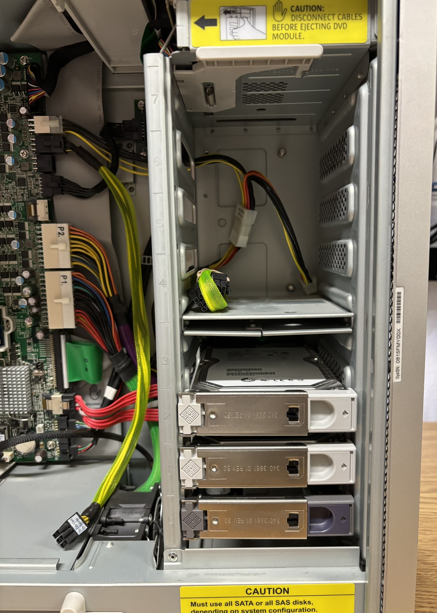
The Ultra 40 M2 supports up to 8 storage drives (SAS or SATA). To install the additional 4 drives, it requires and optional backplane for the top bay. In the image below, you can see 3 hard drives installed in the bottom bay and an unpopulated top bay with the backplane missing. The Sun branded drive carrier trays are often referred to as "spuds". Since the system uses a standard AHCI SATA controller, SSDs work just fine, provided you install them in a 2.5 inch to 3.5 inch drive adapter bracket that preserves the SATA connector position.
This is the front I/O module removed from the system. Once all internal connectors are removed, it ejects by pressing a button directly above the top drive cage. The slot loading optical drive is mounted to the I/O module by two screws on each side and uses an IDE interface.
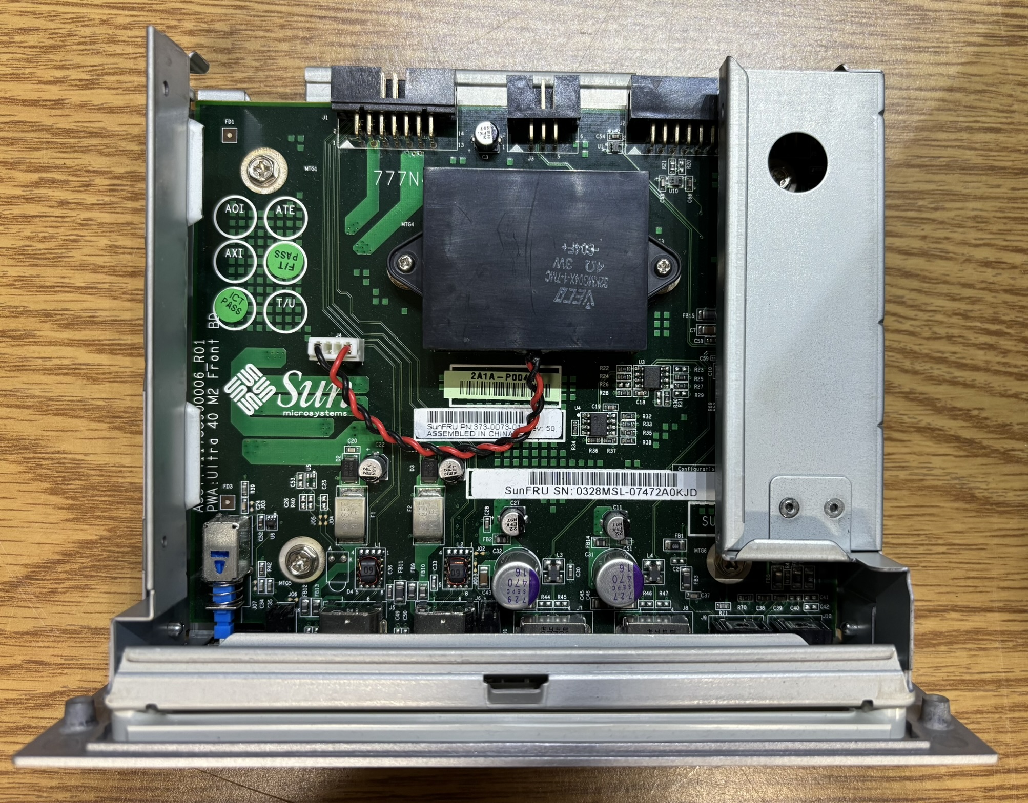
Removing the optical drive reveals a small internal system speaker and the I/O module circuit board.
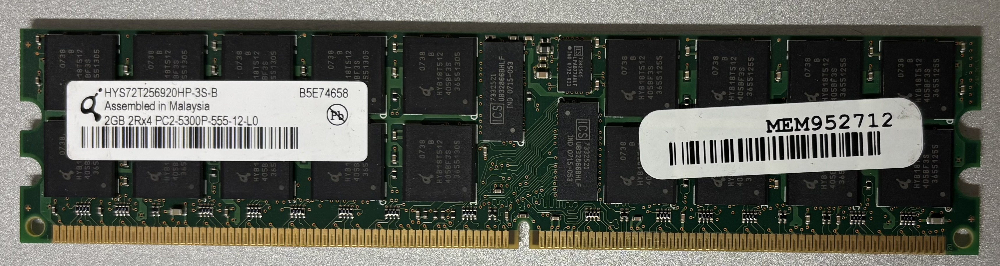
Below is one of the DDR2 memory modules installed in our system. It has 8 identical 2 GB modules, totaling 16 GB of memory. The DIMM module part number is HYS72T256920HP-3S-B and it is manufactured by Qimonda.
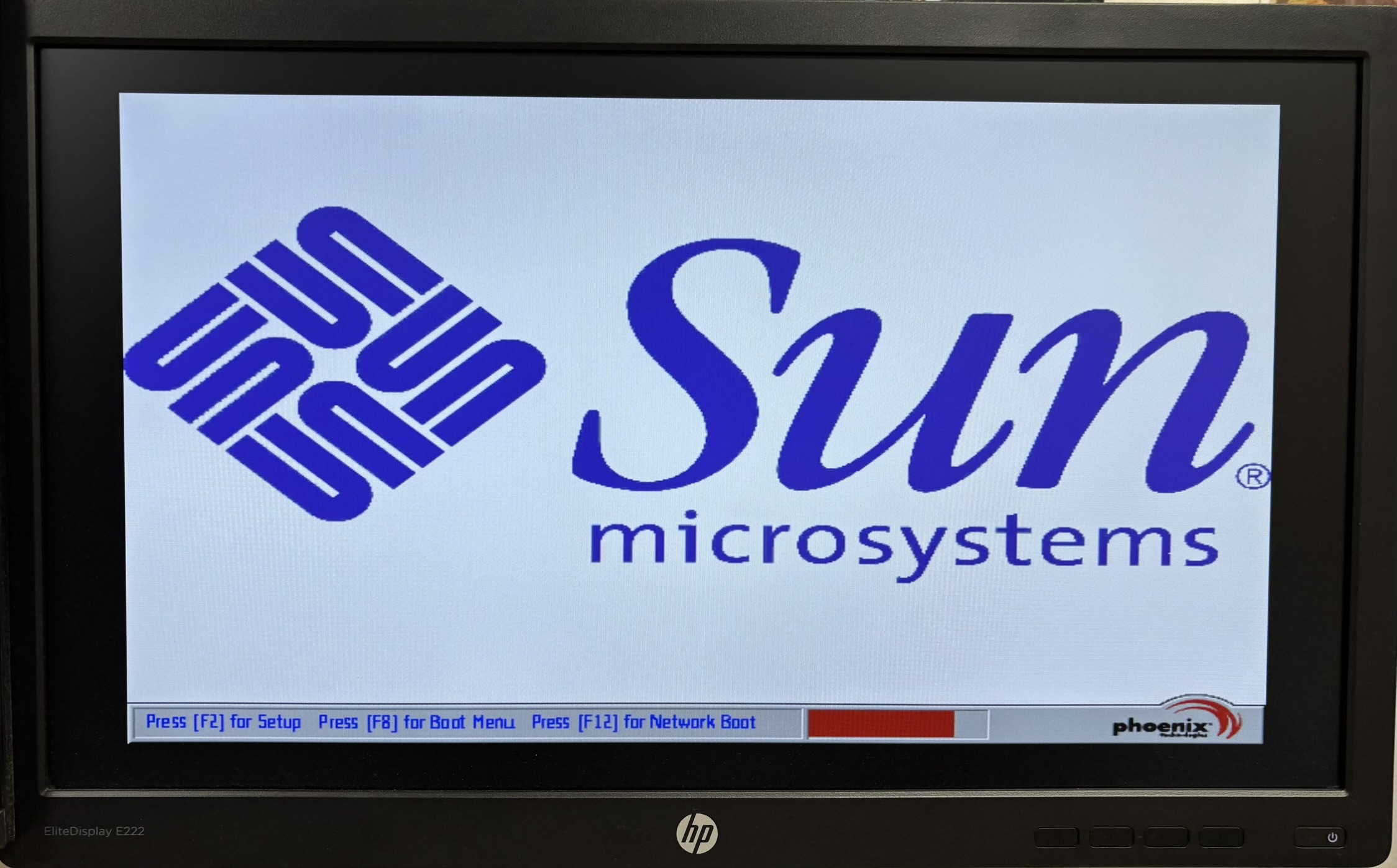
This is the POST splash screen. It displays a small progress bar to indicate POST completion status along with the setup hotkeys.
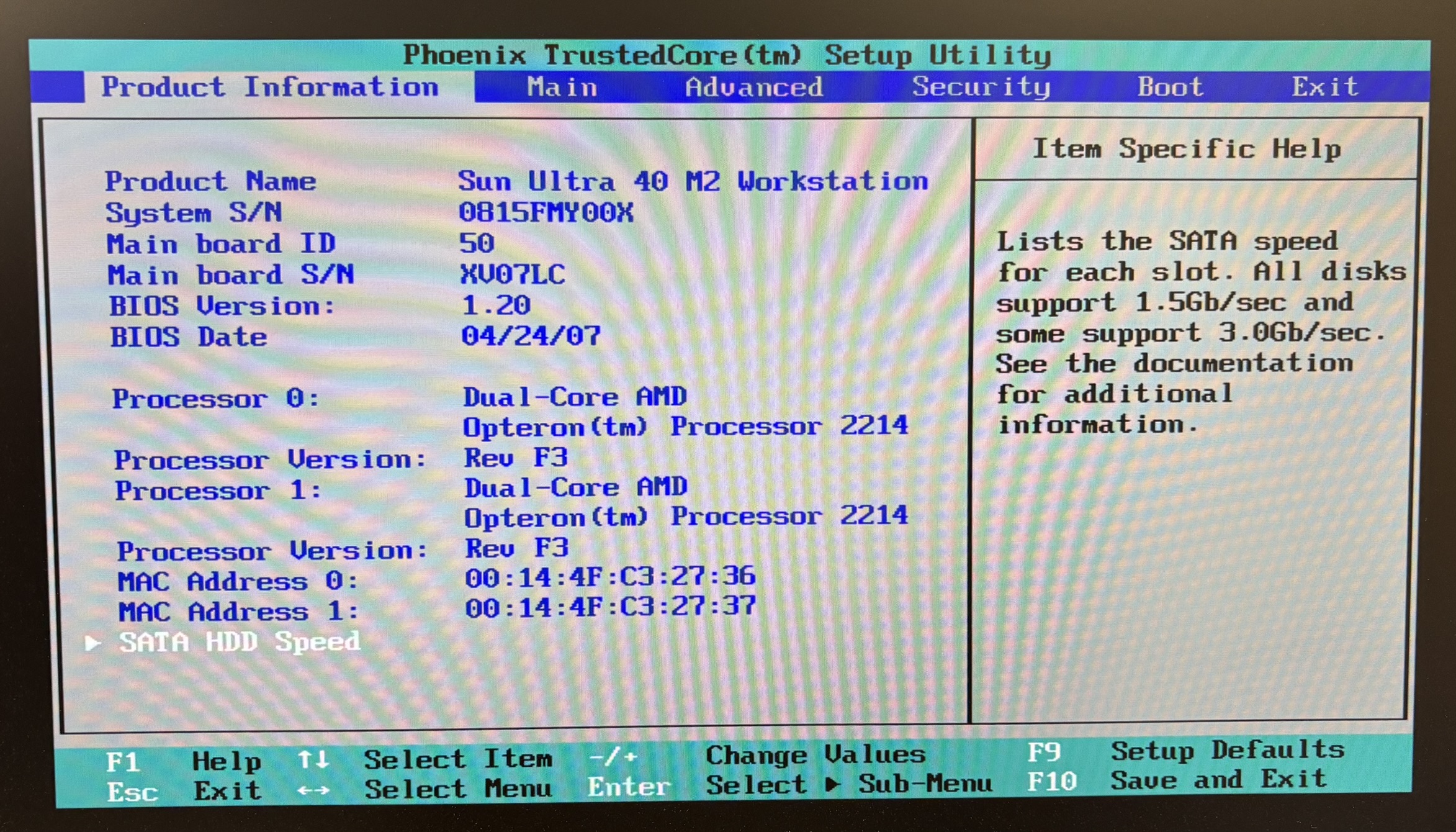
Below is a screenshot of the Phoenix TrustedCore BIOS setup utility. It's a classic text-mode setup program.
Sun Microsystems was acquired by Oracle in 2010. Interestingly, the Ultra 40 M2 service manual is still available for download on Oracle's website. It's an excellent manual that explains how to replace any component and includes detailed troubleshooting steps.