DISCLAIMER: This control panel is a demilitarized surplus component purchased through civilian channels. It contains no cryptographic hardware, classified technology, or active radio capability. It is presented here solely for historical and educational interest. Nothing in this article should be interpreted as technical guidance for operating, replicating, or transmitting on military communications systems.
This control panel was purchased online and likely was removed and sold as part of a military surplus auction. It likely came from a RAF Panavia Tornado GR4, but could have been used in other aircraft as well. The Racal D6915/2 is the control panel used by the pilot for operating the JTIDS (Joint Tactical Information Distribution System) / Link-16 secure communications system. This system allowed for the secure encrypted communication between NATO aircraft and ground installations.
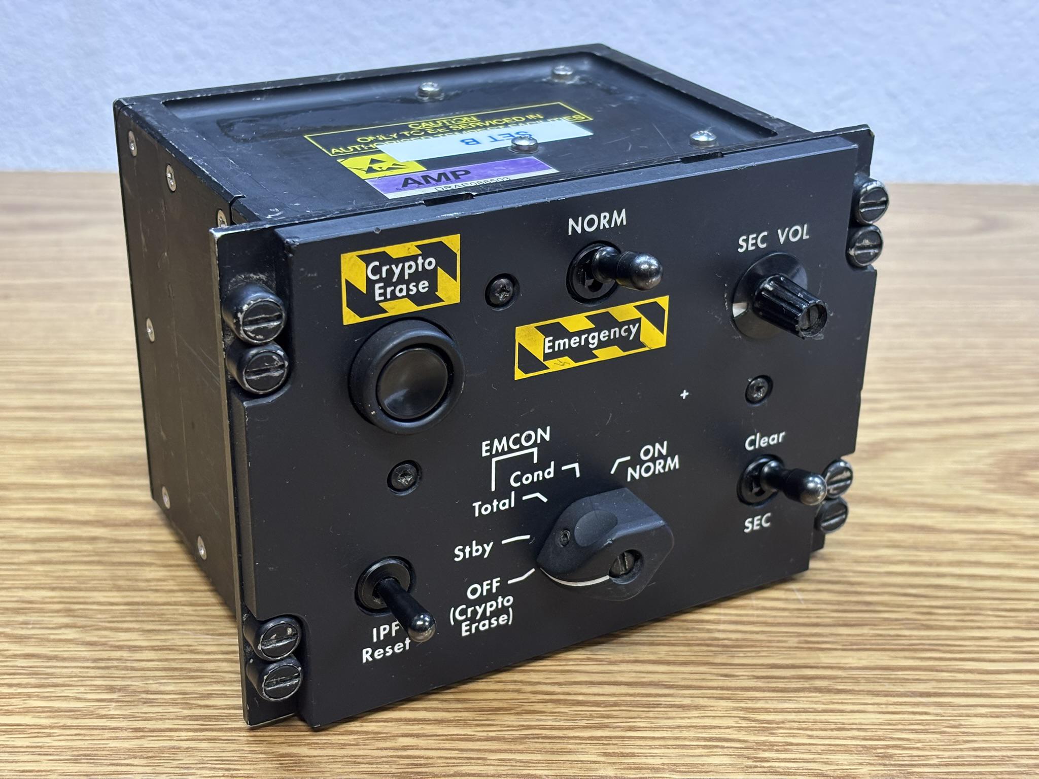
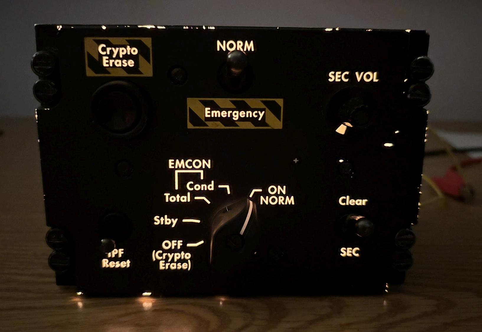
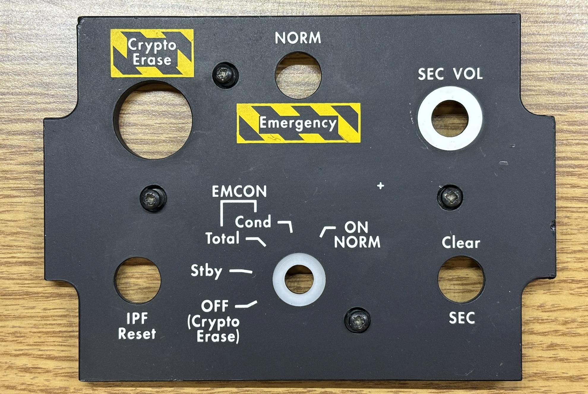
Below is a list of each switch on the control panel along with its function.
Mode Selector Rotary Switch
- OFF: Isolates power from the JTIDS system (totally off), also zeroizes stored encryption keys
- STBY: Standby mode, system is powered on, but not able to transmit or receive (RF disabled)
- EMCON TOTAL: Emission control - total, receive only mode, no RF transmission, used for covert operations
- EMCON COND: Emission control - conditional, minimal RF transmission, only critical or brief messages
- ON NORM: Normal on, fully operational transmit and receive
Crypto Erase Button: Immediately zeroizes (destroys) encryption keys stored within the system. Used in the event of a capture, before a crash, etc. This prevents the enemy from extracting sensitive encryption keys from a captured aircraft.
IPF Reset Momentary Toggle Switch: Resets the interference protection system.
NORM / Emergency Toggle Switch
- NORM: Normal operation mode
- Emergency: Fallback to unencrypted basic radio communication
Clear / SEC Toggle Switch
- Clear: Unencrypted transmission
- SEC: All transmissions encrypted using the currently-loaded keys
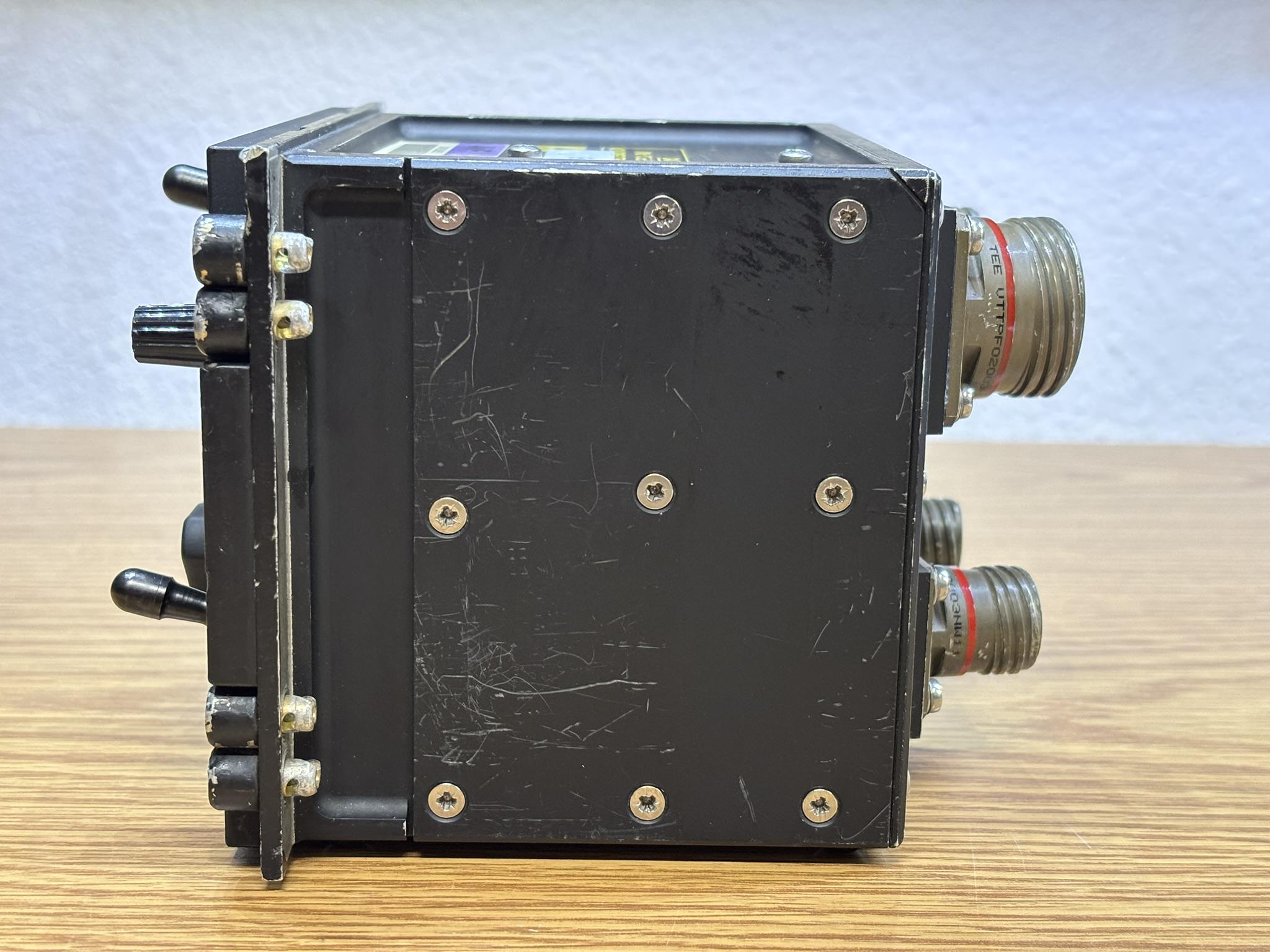
There is no shortage of screws on all sides of this unit! Each side has a panel that can be removed to reveal the internal components.
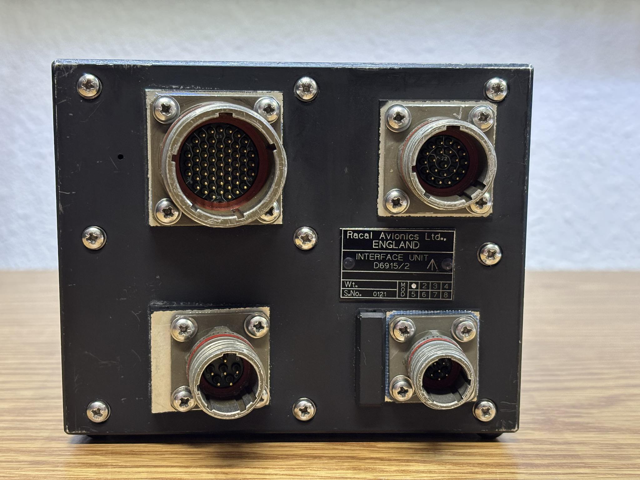
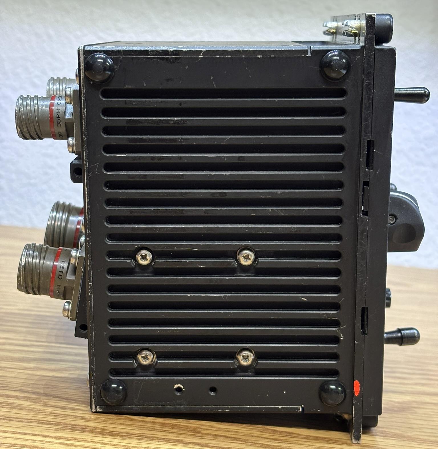
The back of the module has 4 MIL-SPEC twist-lock connectors. 55 pin top left, 22 pin top right, both bottom connectors have 6 pins. These connectors are manufactured by one of several companies such as Amphenol, TE Connectivity, Soriau/EATON, etc.
This is the bottom of the module. The rubber feet were added by the previous owner and are definitely not part of the original equipment.
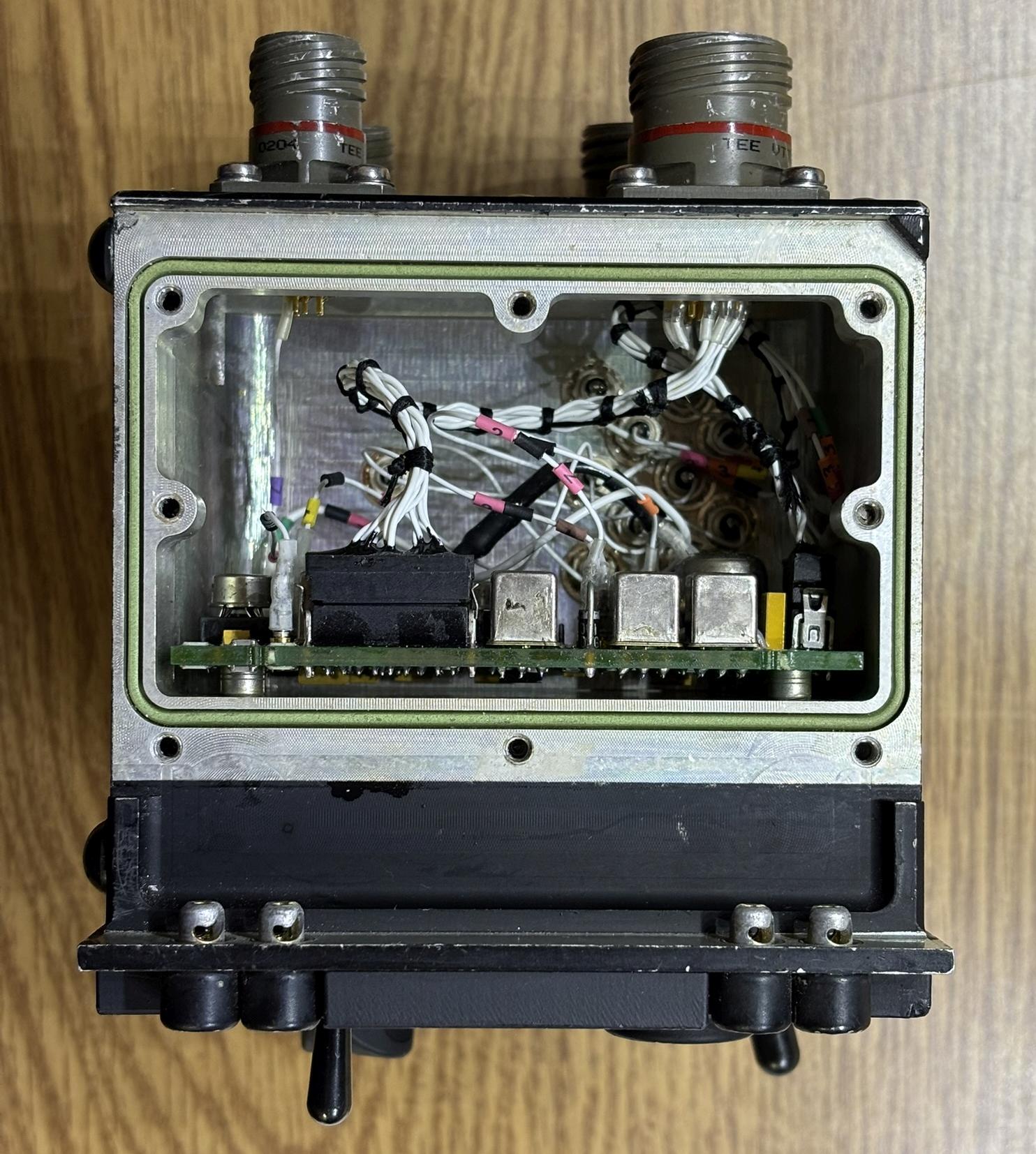
Removing the first side cover reveals a circuit board mounted to the aluminum casing, contained within a sealed cavity. The board has several sealed relays and some other basic components. There is not much active digital circuitry in this device as it's only an interface unit. While it's understandable to not use every pin of a large multipin connector, it seems odd that there is only 1 pin in use out of the 6 on the left connector.
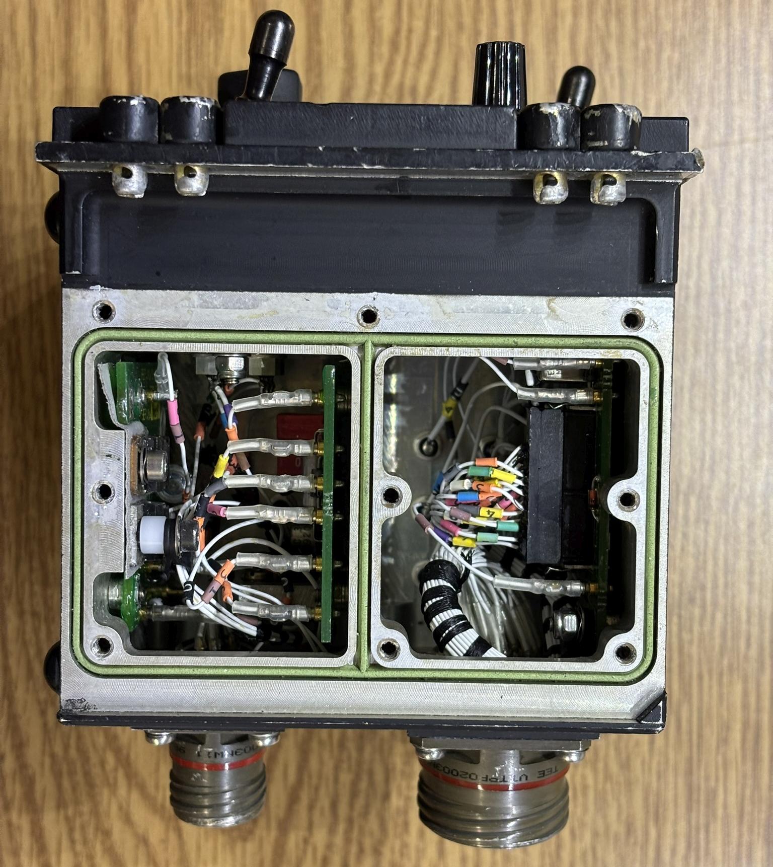
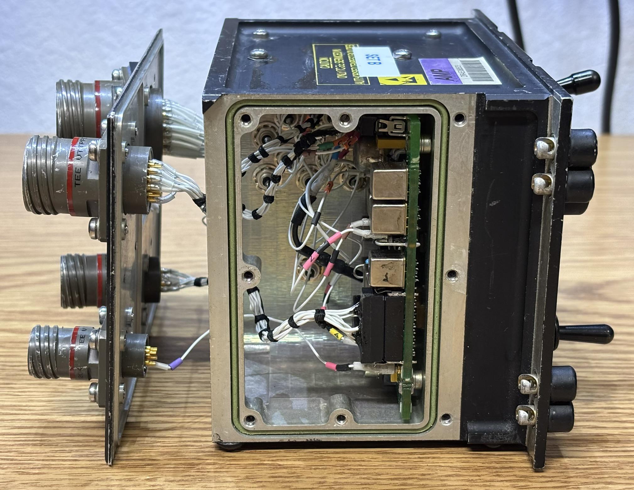
Removing the other side cover reveals two separate sealed cavities, each containing their own circuit boards and connections. Some connections route through to the controls on the front, and others route from the circuit board to the twist-lock connectors on the back.
The front faceplate can be separated from the rest of the assembly once the four screws and control knobs are removed. This faceplate contains a backlight (likely incandescent) that is used to illuminate the switch positions and lettering in a dark cockpit. These faceplates are common in aviation, and feature a translucent plastic design covered in an opaque material. This opaque material is etched away in desired areas to illuminate switches and text. More or less material can be etched to determine how much light passes through.
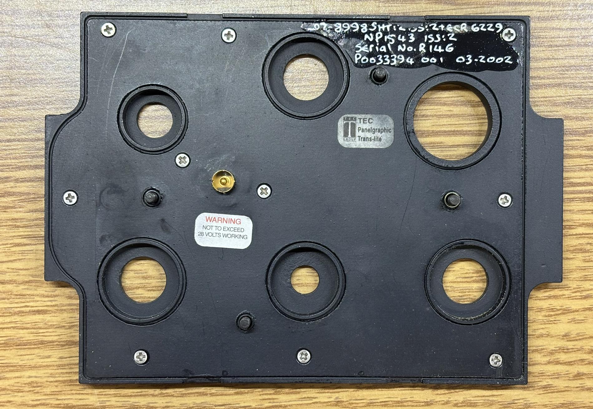
The back side of the illuminated faceplate reveals some model and serial numbers along with the manufacturer label, TEC Group. This faceplate is called a "panelgraphic trans-lite". There is also a small gold connector with a center pin and concentric ring. This connector presses into the matching socket on the interface unit housing to connect the backlight. As indicated by the label, the backlight voltage should not exceed 28 volts. It can be ran at a lower voltage if a dimmer backlight is desired.
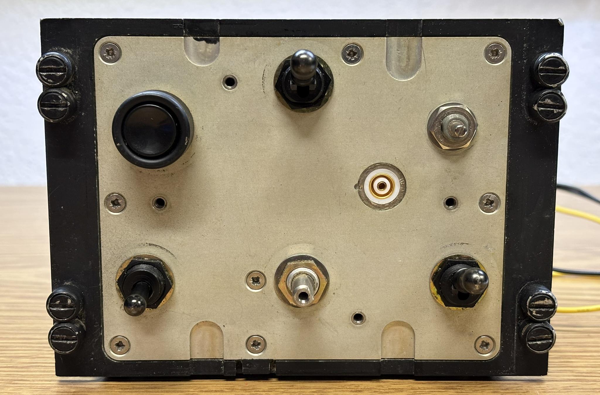
This is the front of the interface unit with the illuminated faceplate removed. It reveals the switches and controls mounted to an aluminum plate along with the mating concentric ring connector for the backlight.
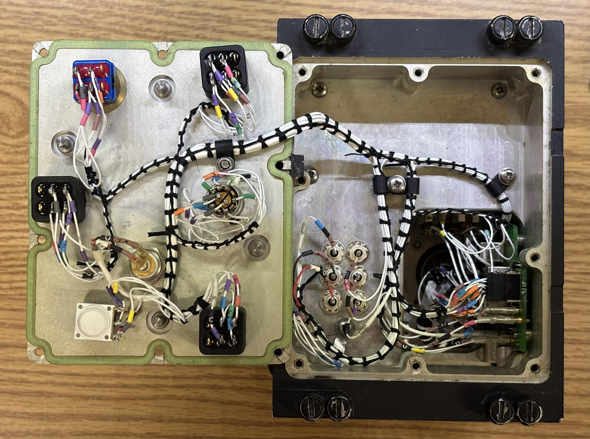
The aluminum plate to which the switches are mounted separates from the rest of the casing once several more screws are removed. All controls route back to the individual sections of the assembly in a beautifully-assembled loom. This level of precision cable-management is common in avionics and very old electronics, but is rarely seen elsewhere. It probably took a skilled tech many hours just to route and tie up those cables. Also, every single wire has a set of colored and identification tags, which makes them easy to trace. One of the circuit boards to which the switches connect to is also visible. Other wires are soldered to feed-through connectors, which essentially just transport the connection through a sealed hold in the casing. This module was clearly designed to have 3 individually sealed cavities. The mission-critical nature is what makes devices like this so amazing. When you just can't afford to have it fail, everything must be done perfectly, and traditional design and manufacture methods are preferred.
Here is a closer look at the front of the largest circuit board. The mounting screws were removed and it was pulled out from within the housing without disconnecting all the wires. There are several sealed relays, canned op-amps, and a TDA7052 audio amplifier. There is an interesting combination of surface mount and through hole components on the board.
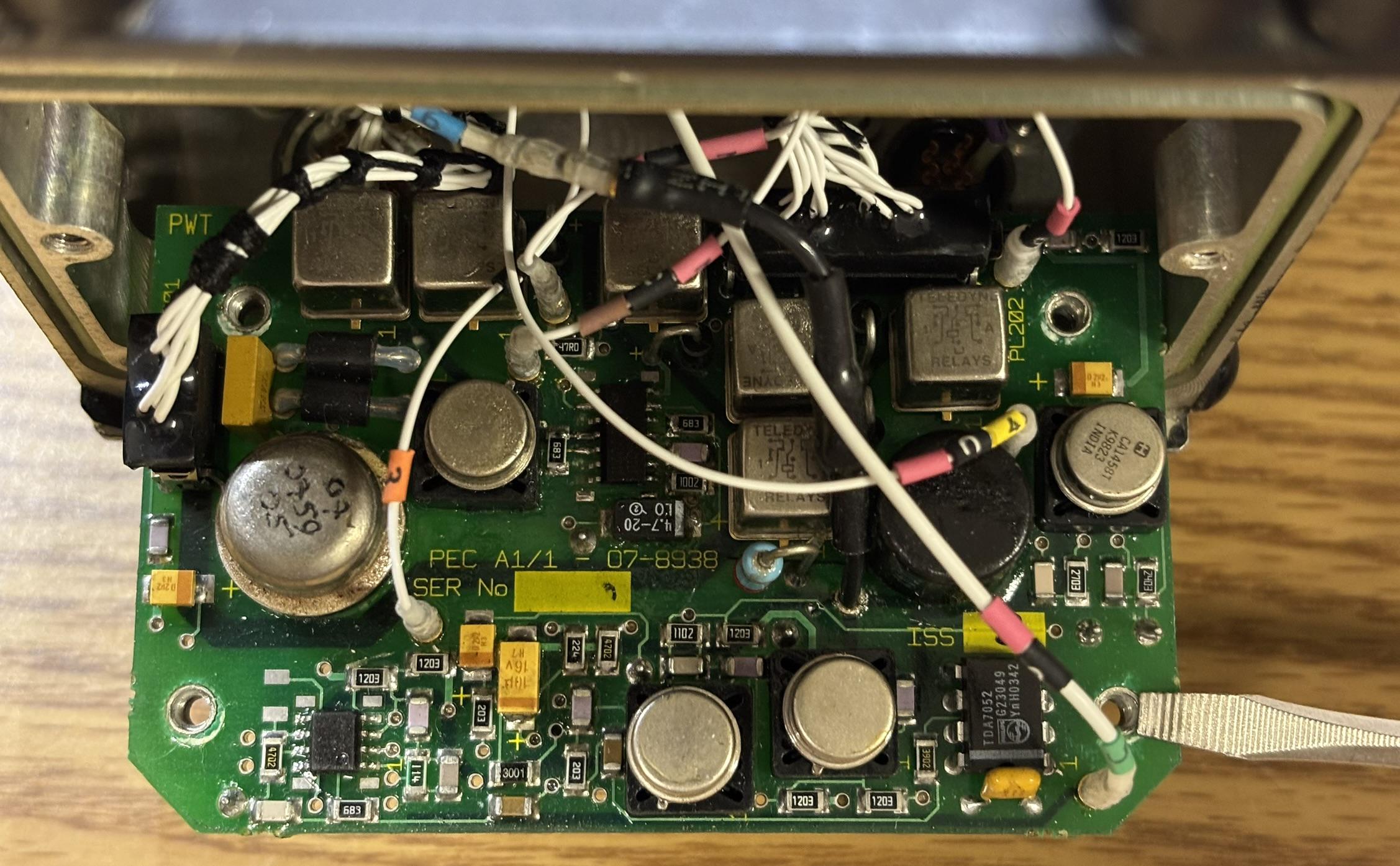
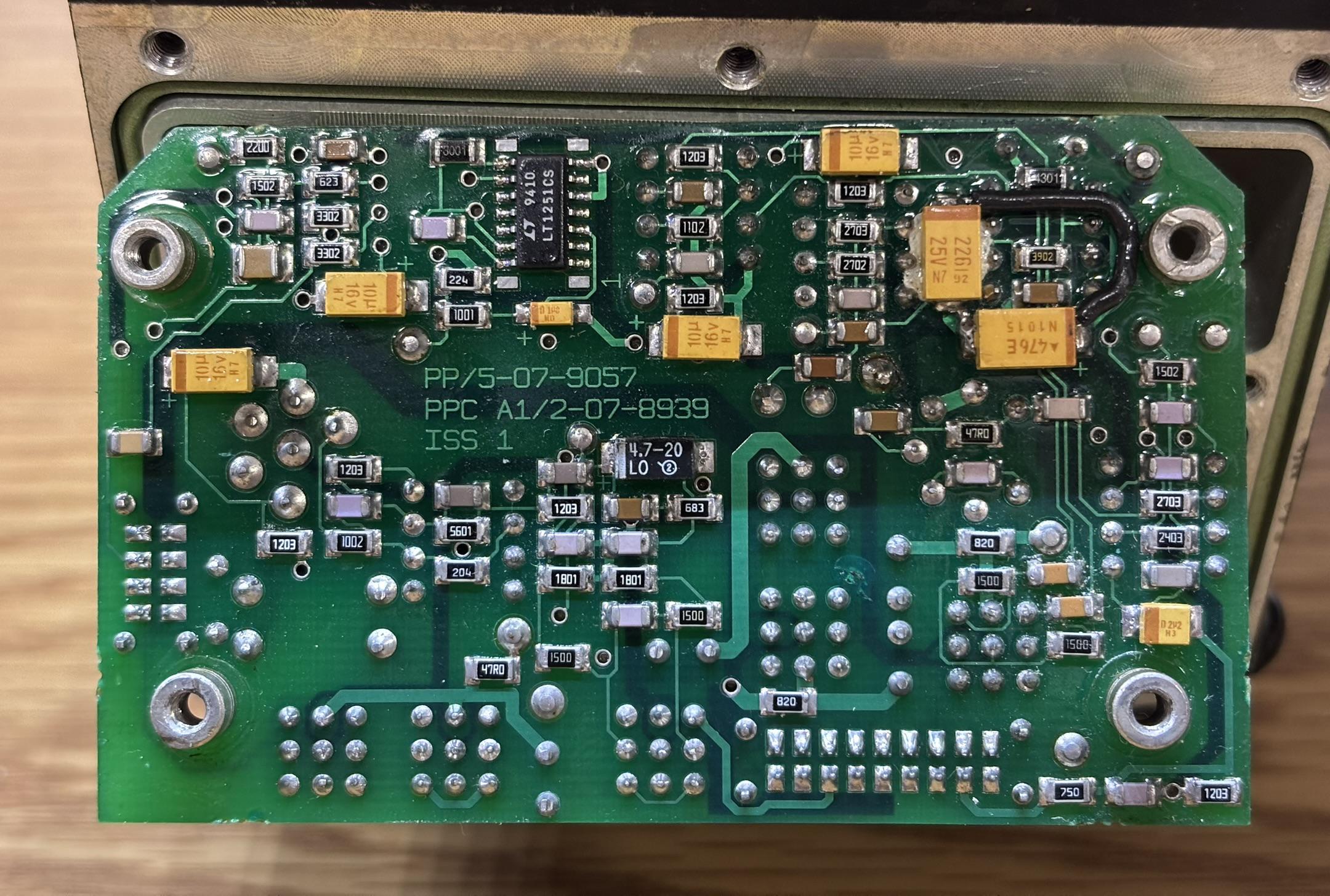
The back of the board contains many surface mount resistors and capacitors along with an LT1251 video fader and gain controlled amplifier.
In the image below, we removed the back panel to show how the wires are installed into the twist-lock connectors. The two connectors closest to the camera are connected to the circuit boards via sockets so they can be easily removed. The other two connectors farthest from the camera are either connected using individual pin sockets or soldered to feed-throughs.
We were able to get the backlight to illuminate by applying 28 V DC to pin E of the left-side 6-pin connector on the back panel and using pin D of the same connector as ground. The backlight intensity can be varied by adjusting the voltage, but do not exceed 28 volts. The edges of the illuminated faceplate have been scratched up a bit, which is why there is some light bleeding through in various places where it should not be.