The CIS Secure DTD-8841-01D1A is a Cisco CP-8841 VoIP phone that has been modified in several ways to be TSG compliant, enabling it for use in SCIF and SAPF environments. We will go into details of each modification below. But first, we would like to cover the goals of CIS Secure and the purpose of their products.
CIS Secure purchases commercial IT and telecommunications equipment such as computers, IP phones, video conferencing systems and much more. They individually modify them to bring them up to a level of compliance required by the customer, which can vary. The National Telecommunications Security Working Group (NTSWG), formerly Telecommunications Security Group (TSG), designs policies for using telecommunications devices in secure and sensitive environments. CIS builds devices to comply with these requirements. Unsurprisingly, customers of CIS Secure are essentially just government and intelligence agencies. While it is possible they they may cater to private or public businesses with specialized security needs, we would not expect that to be a very large portion of their customer base. Below is a list of just a few products that CIS Secure sells:
- Webcams with enhanced camera active indicator LEDs and built-in shutters
- VoIP phones with microphones and/or speakers removed
- Fiber-enabled VoIP phones with positive disconnect features
- Videoconferencing systems with positive disconnect features
- Desktop computers and thin clients with custom metal chassis to enhance durability and minimize radio frequency emanations
In this write up, we will be focusing on the DTD-8841-01D1A VoIP phone from CIS Secure. This unit was purchased online from eBay in new condition. It was likely purchased by mistake or is an older model that was not put into service. It came in a CIS-branded box and original packaging from CIS Secure, including the AC power adapter. Most people will never get a chance to see a device like this due to the incredibly specialized nature of its application. If you have seen or worked with a device like this, you probably hold some sort of security clearance. We are pleased to offer an overview, disassembly, and explanation of the device.
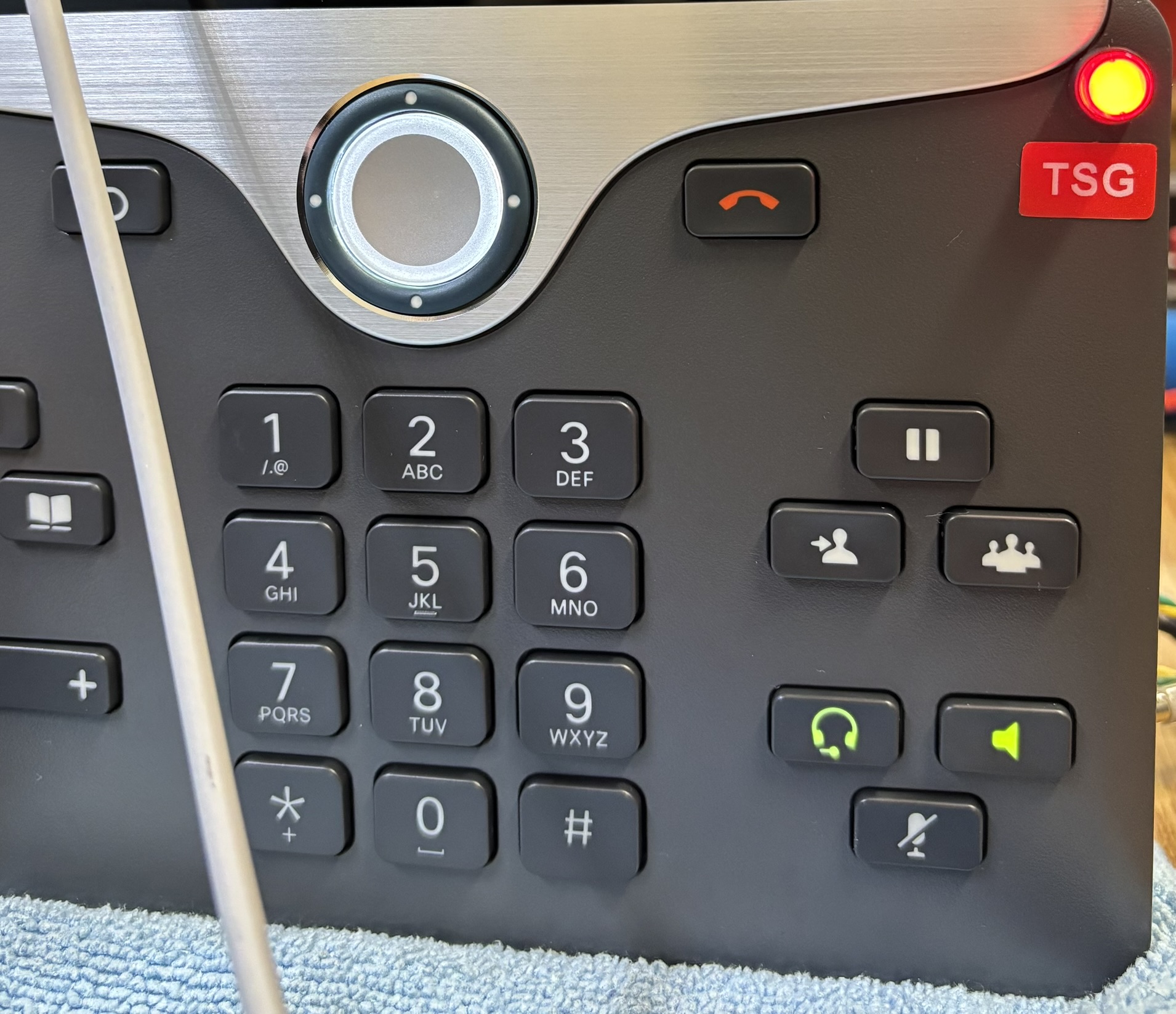
From the front, the DTD-8841-01D1A looks like a typical Cisco CP-8841 with only a few noticeable differences. The first change on the front is a label that was applied over the top section which has both the Cisco and CIS Secure logos. More obviously, is the red button labeled TSG (Telecommunications Security Group). This is not a Cisco factory feature and was added by CIS Secure. The TSG button is how the user can activate and control the positive disconnect feature of the phone. It will be explained in detail later, but essentially it disconnects all audio devices (microphones and speakers) until the user presses the button to enable it. The button also lights up red to indicate when the audio devices are active.
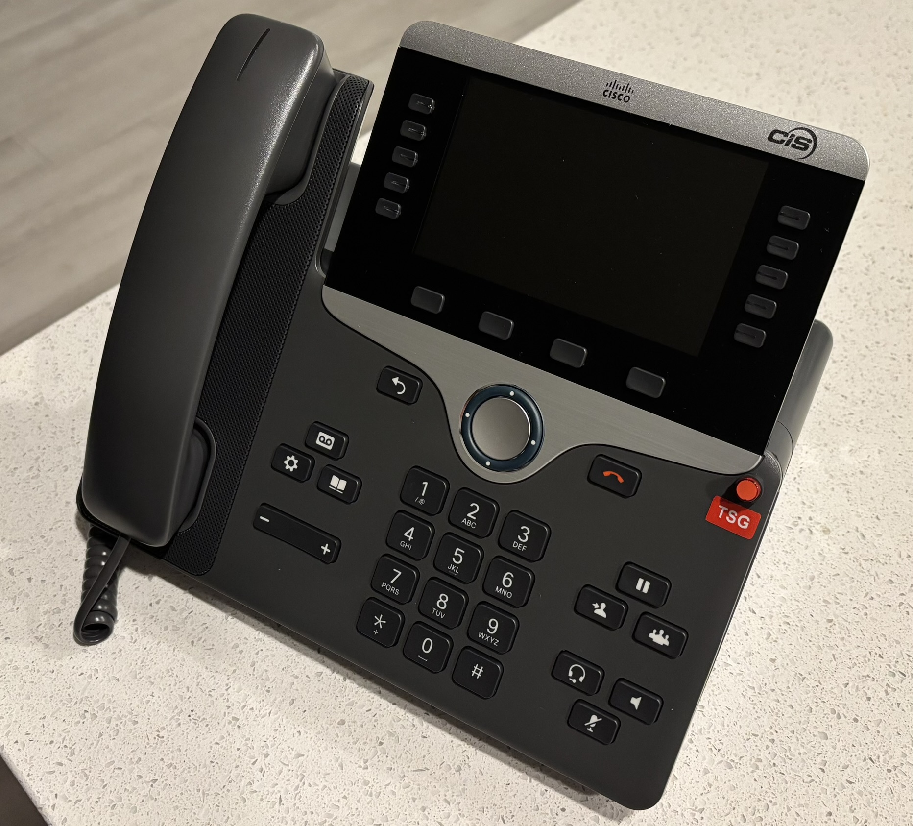
The positive disconnect system has 3 possible states, which are listed below:
- Positive disconnect system STANDBY - microphones and speakers DISABLED, TSG button LED OFF
- Positive disconnect system READY - microphones and speakers DISABLED, TSG button LED OFF, can switch to ACTIVE by pressing TSG button
- Positive disconnect system ACTIVE - microphones and speakers ENABLED, TSG button LED ON, can switch to READY by pressing TSG button
The following conditions will cause a transfer from one state to another:
- No active call, handset on hook -> STANDBY
- No active call, handset off hook -> READY/ACTIVE
- Speaker or headset mode active -> READY/ACTIVE
- Call in progress using handset/headset/speaker -> READY/ACTIVE
- Hanging up the handset -> STANDBY mode
- Ending a call on headset or speaker -> STANDBY
- Phone is ringing - special override mode that enables ONLY the built-in speaker
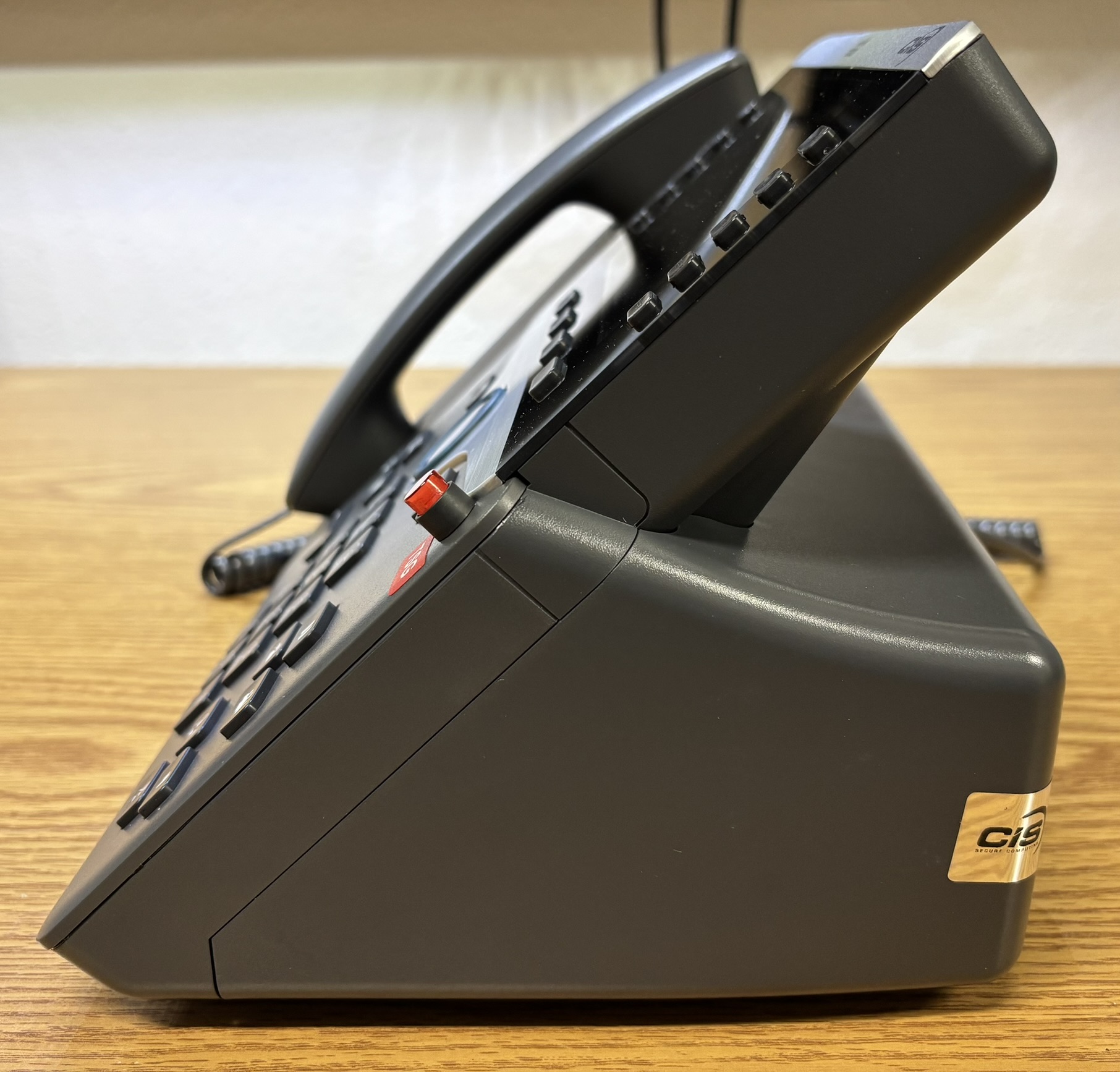
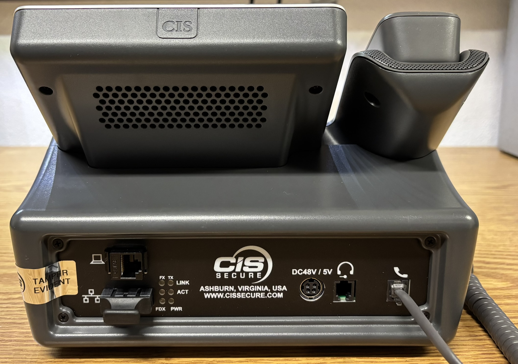
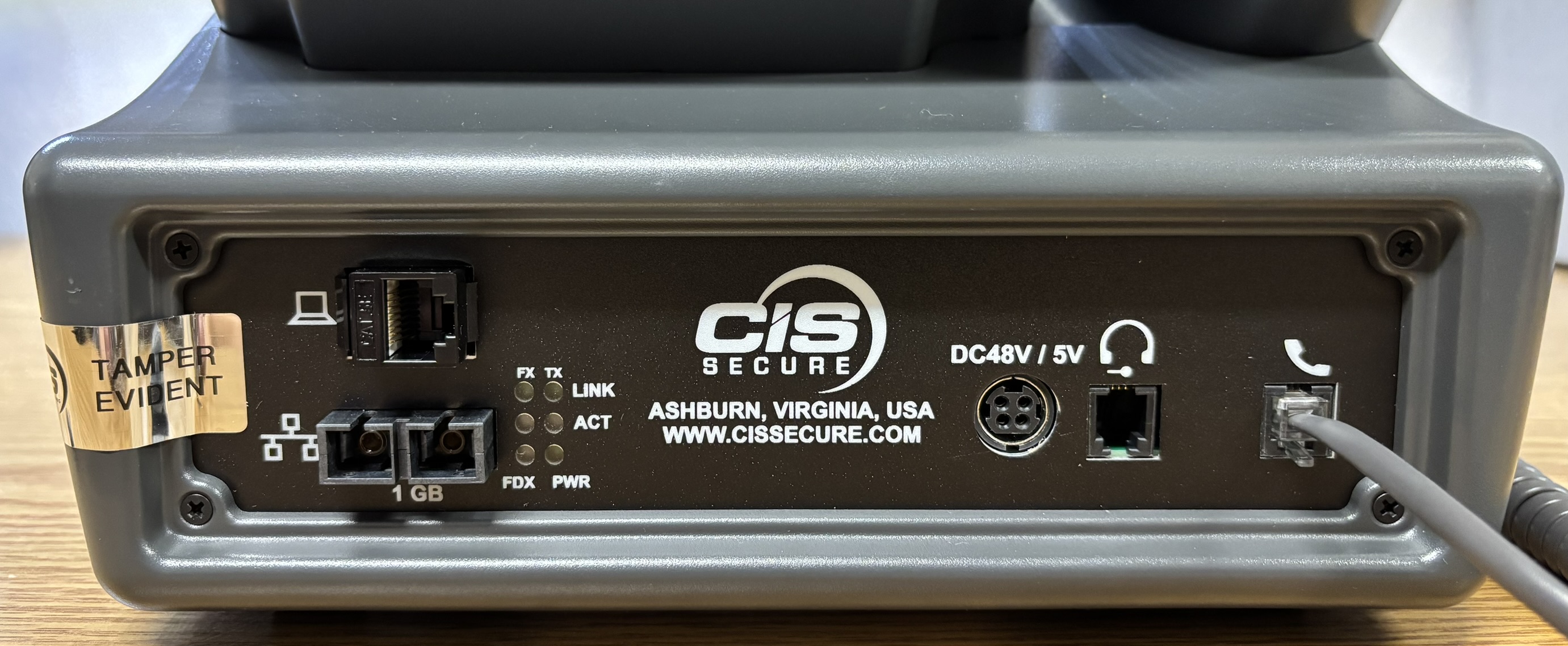
The side and back are where it becomes very apparent that this is not a standard Cisco IP phone. The original rear enclosure and stand has been removed and replaced by a custom enclosure. CIS Secure has done a pretty good job of fabricating a large plastic case that mates to the back of the phone. The unmodified Cisco CP-8841 is much slimmer and just has an adjustable stand on the back. The reason for this extra large enclosure is two-fold. First, it needs to contain all of the circuitry and components for the positive disconnect feature, also it houses an optical fiber to Ethernet (copper) media converter. Depending on the model ordered from CIS Secure, these phones can be configured with fiber network interfaces for the LAN and PC side, or just the LAN side as with our model. Other, less secure models only contain the positive disconnect components and don’t feature a fiber network interface at all. CIS Secure also has a model of this phone called the slim version, which omits any fiber interface and fits all the positive disconnect circuitry into the original casing of the phone without the need for a custom rear enclosure.
Fiber networking is common in datacenters for connecting servers and in network closets on switches. Often, fiber is needed for long distance and/or high bandwidth connections. Optical fiber interfaces on devices such as a desktop computers and IP phones are uncommon. Sometimes they are used for high bandwidth communication to workstations, but it’s simply not necessary in most cases. A single IP phone or computer will not usually be located very far away from a distribution switch to warrant the need for fiber. As far as bandwidth, an IP phone definitely isn’t going to need very much, so fiber would generally be unnecessary. The reason for the fiber interface on this DTD-8841-01D1A is all about security.
A lesser-known advantage of fiber as a network transmission medium is that it's more secure compared to Ethernet or Wi-Fi, from the standpoint of emanations. It is feasible (and has been proven) that radio-frequency emanations from Ethernet and other voltage-based data communication media can be picked up by very sensitive and specialized equipment. Pattern analysis combined with advanced knowledge of the target system and the communication protocols could enable an attacker to extract critical data from these emanations. By using optical fiber as the data transmission medium, this risk can be completely avoided as optical fiber uses light to transmit data, not electrical energy. Unless the fiber cable was somehow broken and spliced into (very difficult), there is no way of externally intercepting the data during transmission. You would (in theory) not have to physically interact with an Ethernet connection to capture and intercept radio-frequency emanations from the medium. And of course, wireless networking is not suitable for use in any environment where security is paramount. A notable downside of optical fiber networking for use in devices such as IP phones is the lack of PoE. You can transmit data over an optical fiber connection, but you cannot transmit power in the same way you can over a copper-based medium such as Ethernet. Therefore, any fiber-enabled IP phone such as the DTD-8841-01D1A requires a suitable power adapter to function.
The included power supply is a LFEVC60NR485 from EOS Power Solutions and is made in India. CIS has assigned their own part number to this power supply: DTD-TPES61. The power supply has a wide range input (100-240 V AC, 60 Hz) and outputs both 48 V DC and 5 V DC. The 48 V rail is passed directly to the IP phone just as PoE power or the Cisco adapter would. The 5 V rail is used for the internal optical fiber media converter that has been installed in the phone by CIS Secure. The connector is a round, 4-pin, locking type that was actually bent during shipping of our unit. We were able to straighten it out with a pair of pliers. Of course, we disassembled the power adapter included with the DTD-8841-01D1A to see if it's anything special.
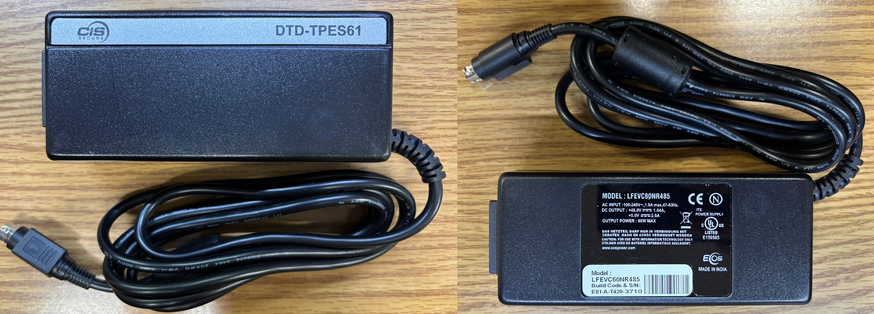
Getting this power supply open was quite a chore, resulted in significant damage to the casing, but did not result in damage to the electronics. We had to pry it open around the seam where the two halves of the casing come together. We are unsure of whether this is an unmodified unit from EOS Power or if CIS Secure has modified it. The casing was very strongly sealed, but it looks like plastic sealant or cement was used around the seam, potentially indicating a modified unit. We cannot be 100% sure of that. It is equally possible that this power supply was modified by EOS Power as a special product for CIS Secure.
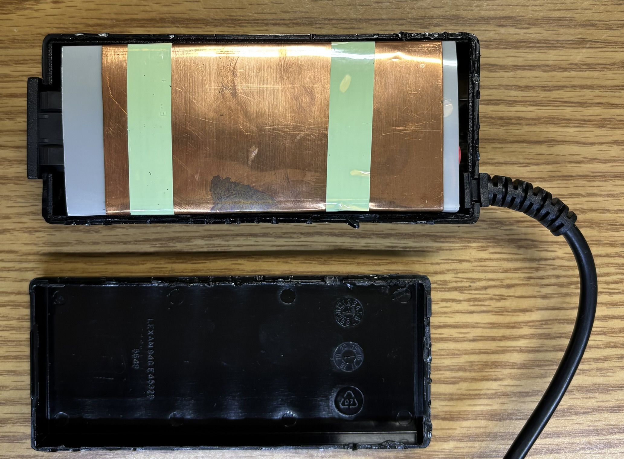
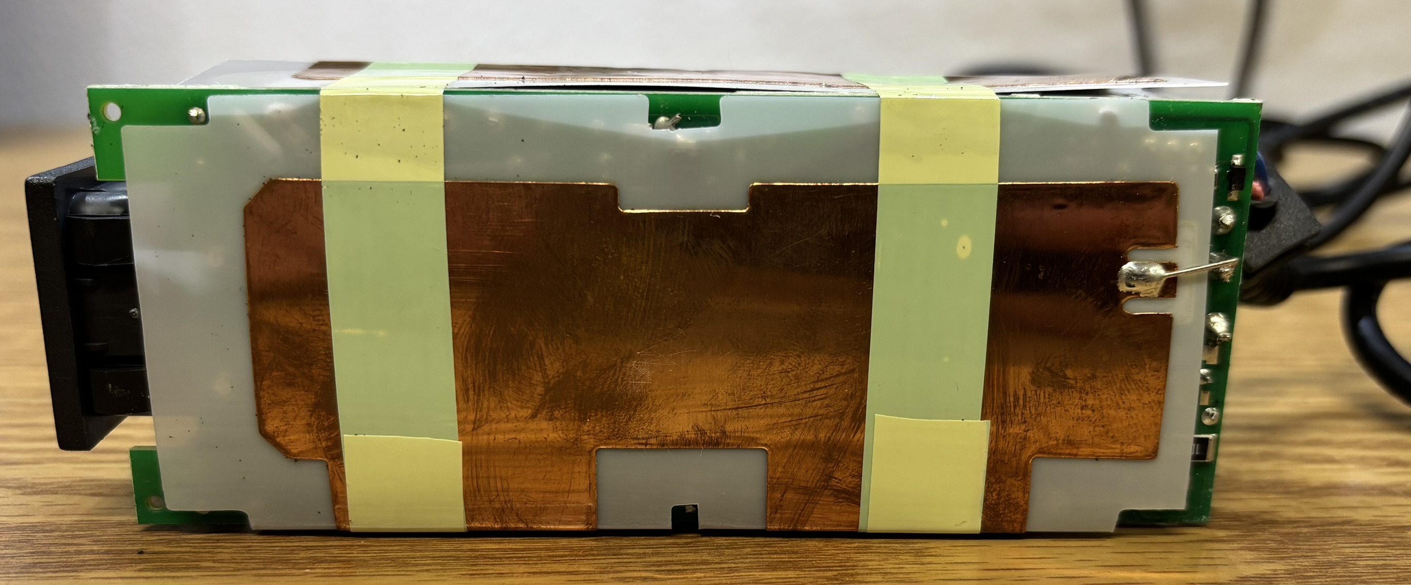
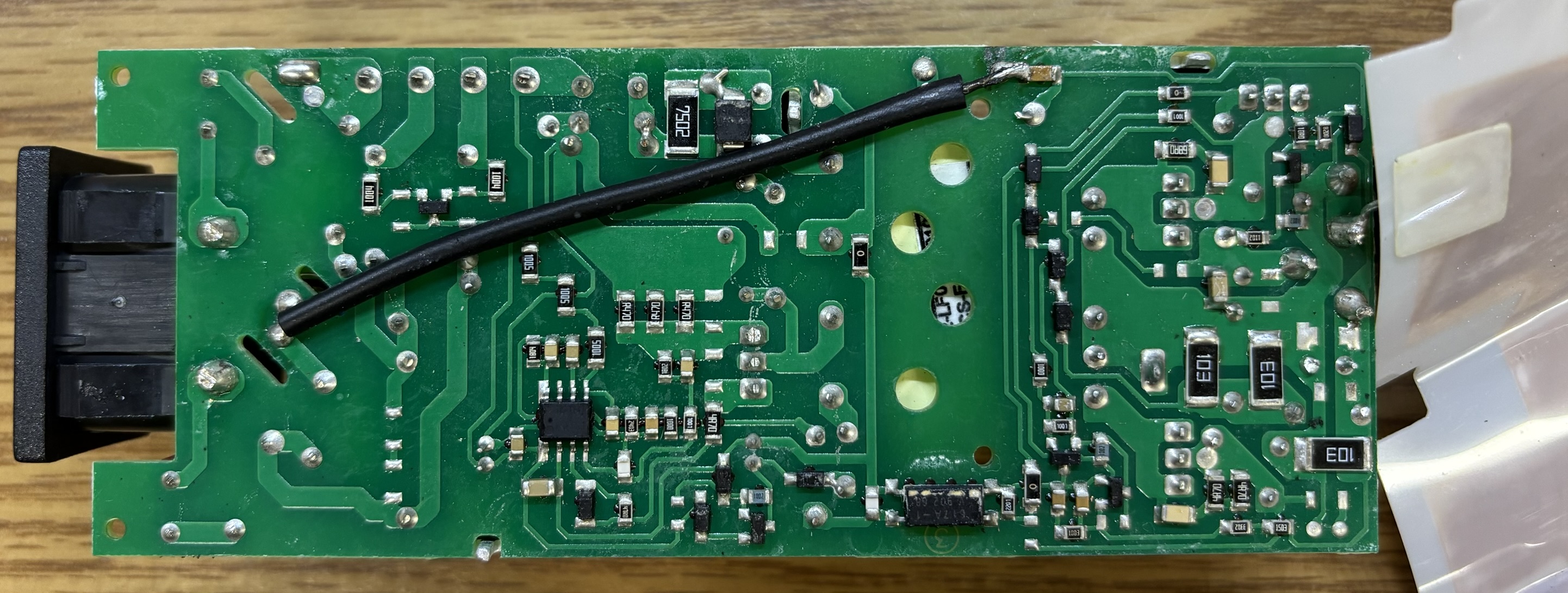
There is one key difference that this power supply does not have in common with a standard "brick" style external power supply. It has an additional layer of copper shielding that wraps around the plastic insulating layer. The shielding is soldered to a ground connection on the circuit board and goes all the way around the electronics. This is most likely done to minimize radio-frequency/electromagnetic interference from the power supply. For the same reason copper networking such as Ethernet is susceptible to pickup of emanations, the electronics of the power supply are susceptible as well. We have not seen a layer of shielding like this in any other brick style power supply.
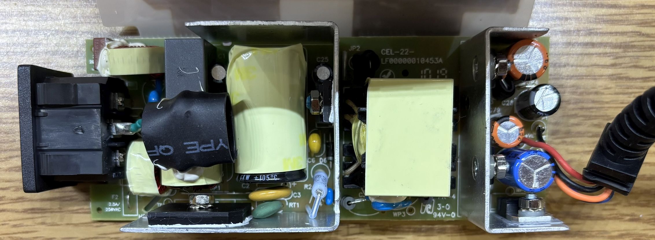
The power supply seems to be well-made, but aside from the copper shielding, is nothing interesting. Below are pictures of both sides of the circuit board.
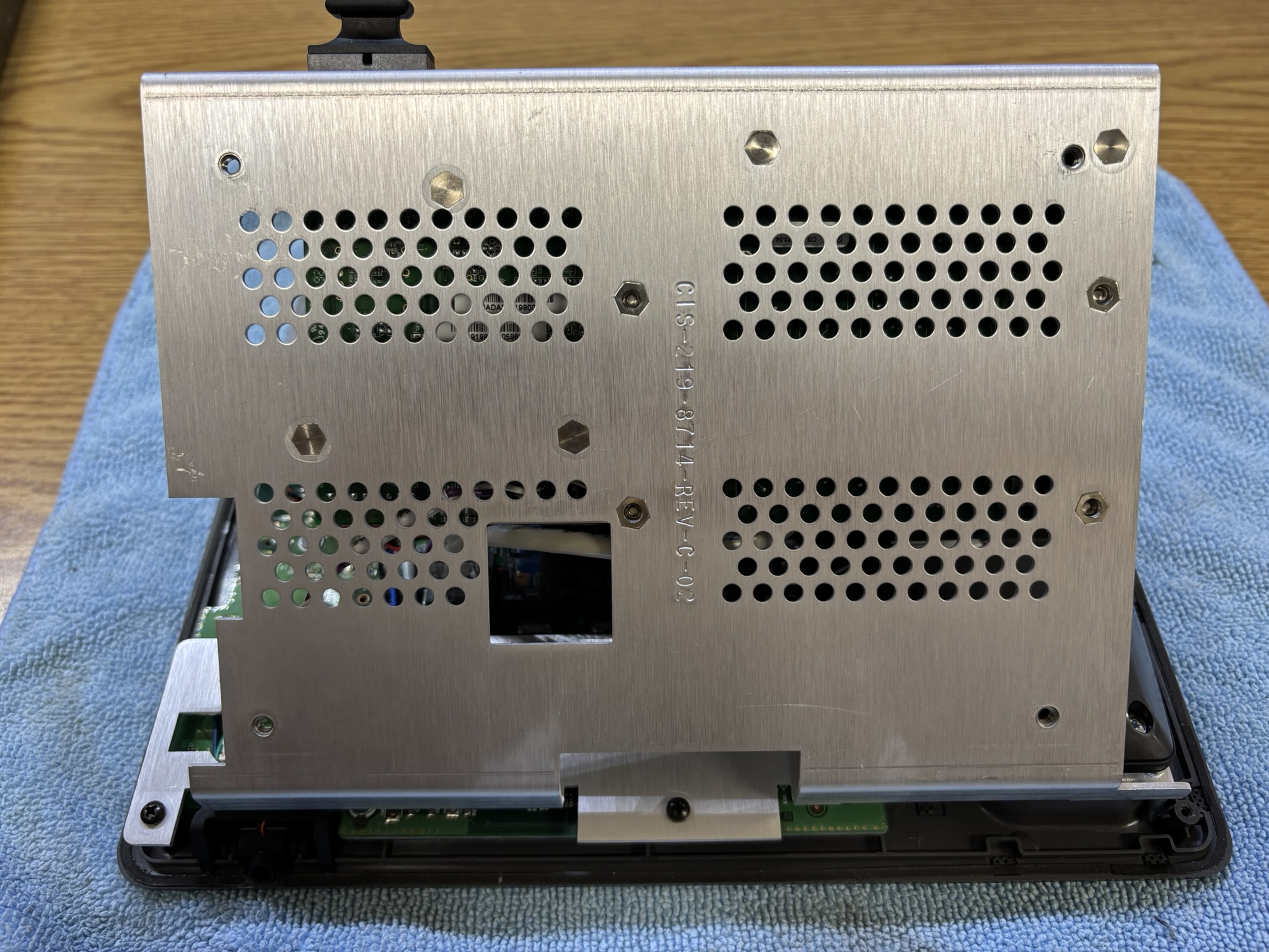
Moving on to the inside of the phone is where things get interesting. Removal of the back casing reveals an entire custom aluminum plate that was designed by CIS and mated to the phone.
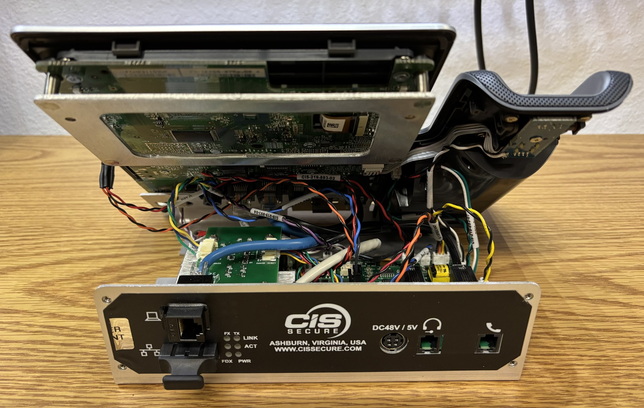
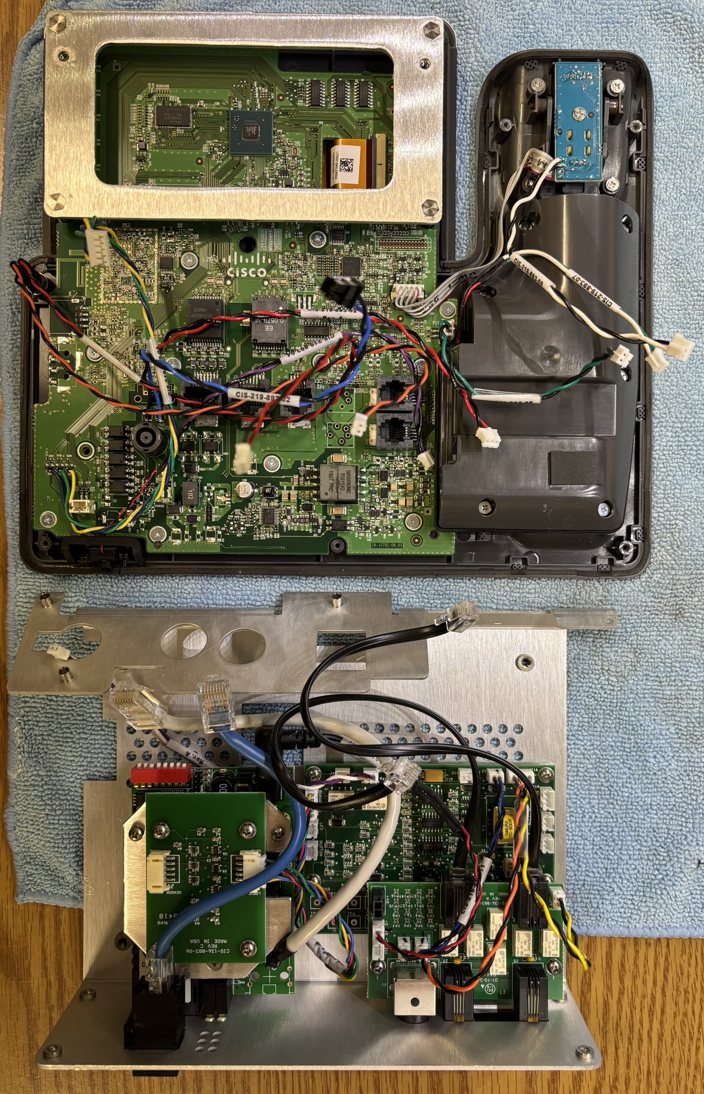
There is a large amount of electronics and wiring that is not part of a standard Cisco CP-8841. This is primarily the circuitry required for the positive disconnect system, but also includes a fiber media converter.
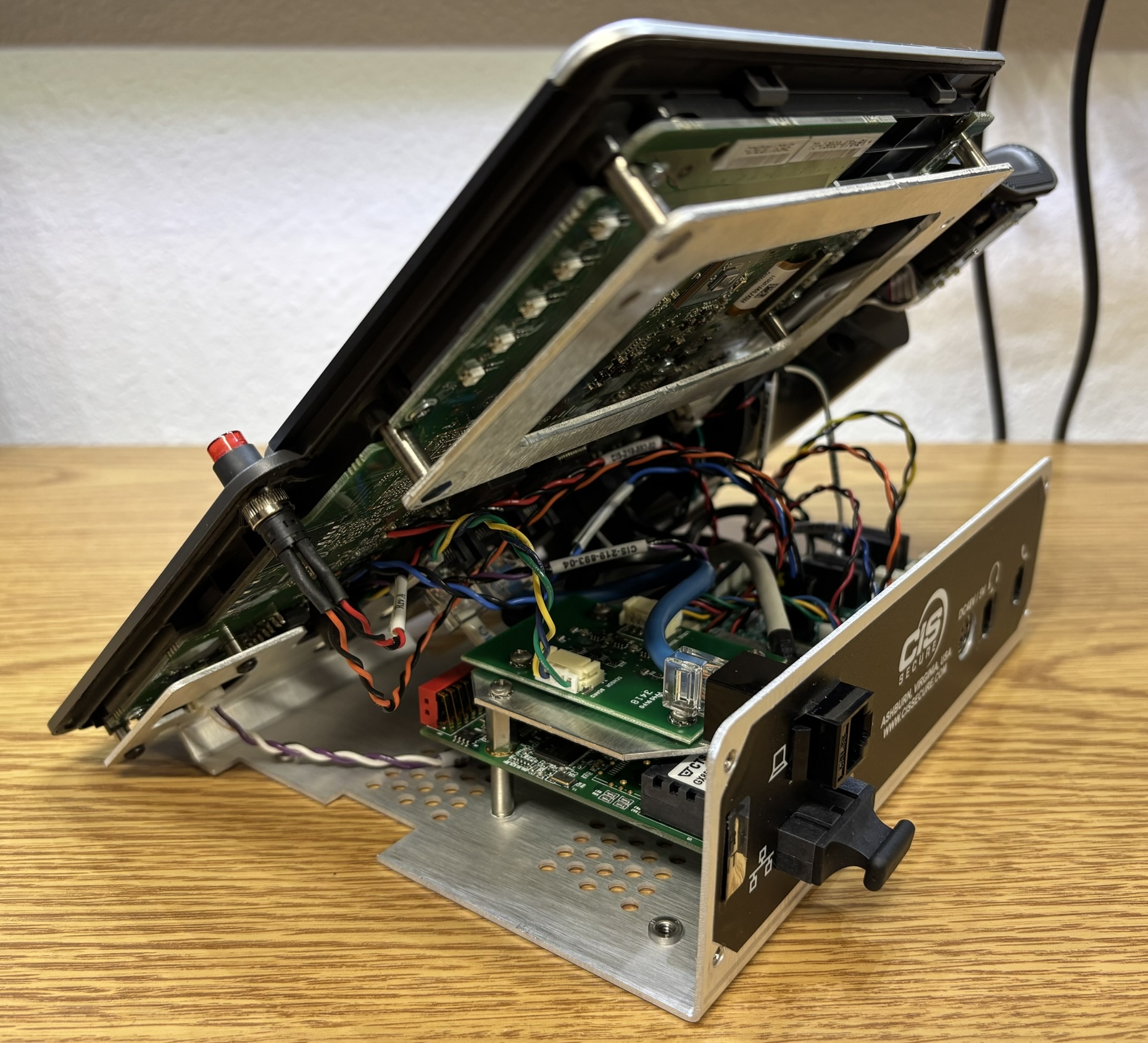
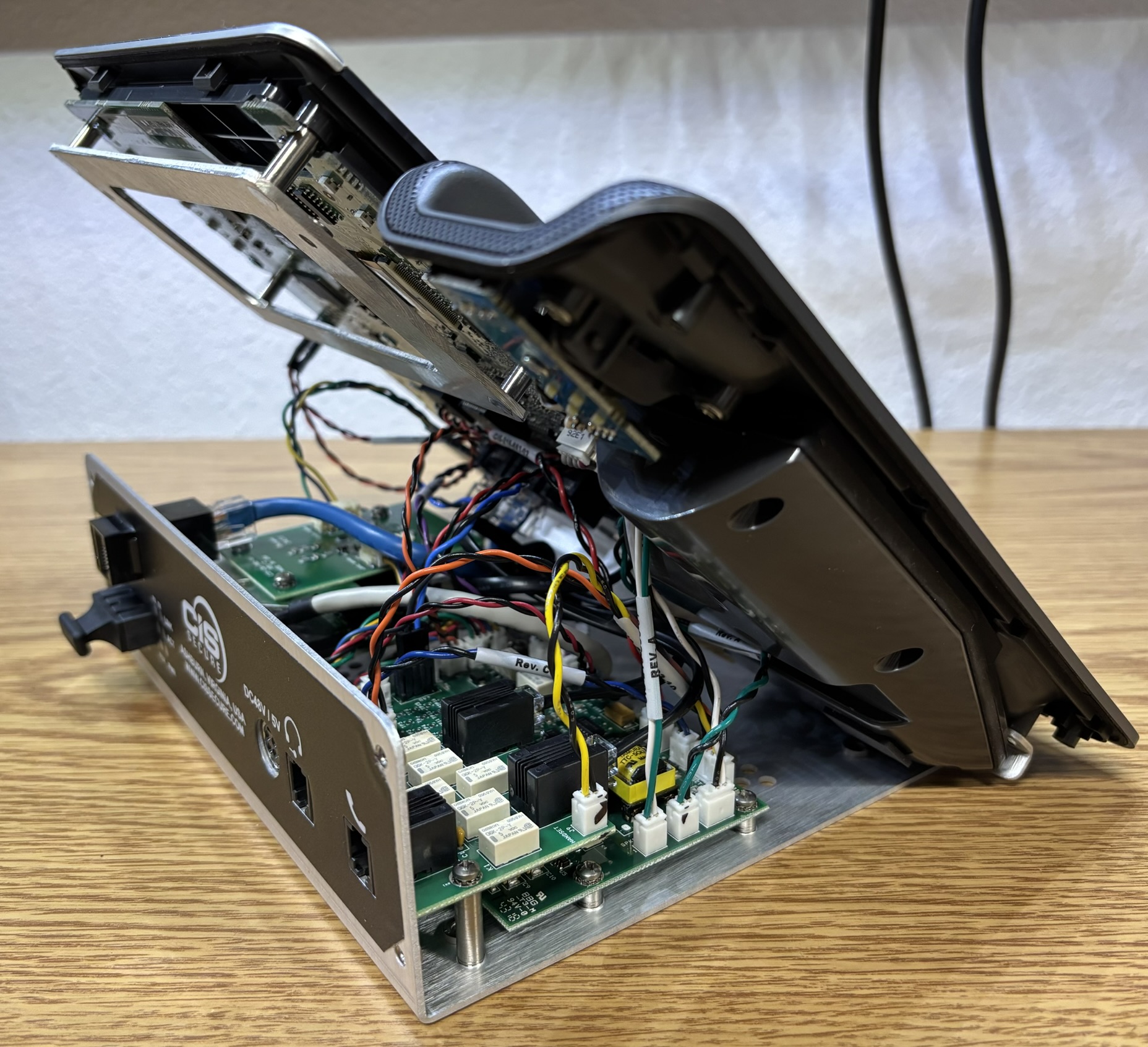
In the picture below, the phone has been split into two halves. The top portion is almost all original Cisco components, aside from some extra wiring. The bottom is all custom electronics designed and installed by CIS Secure. The includes multiple positive disconnect control boards, a sensor interface board, and a fiber media converter. There is a large amount of wiring that goes between these boards and the phone and its components.
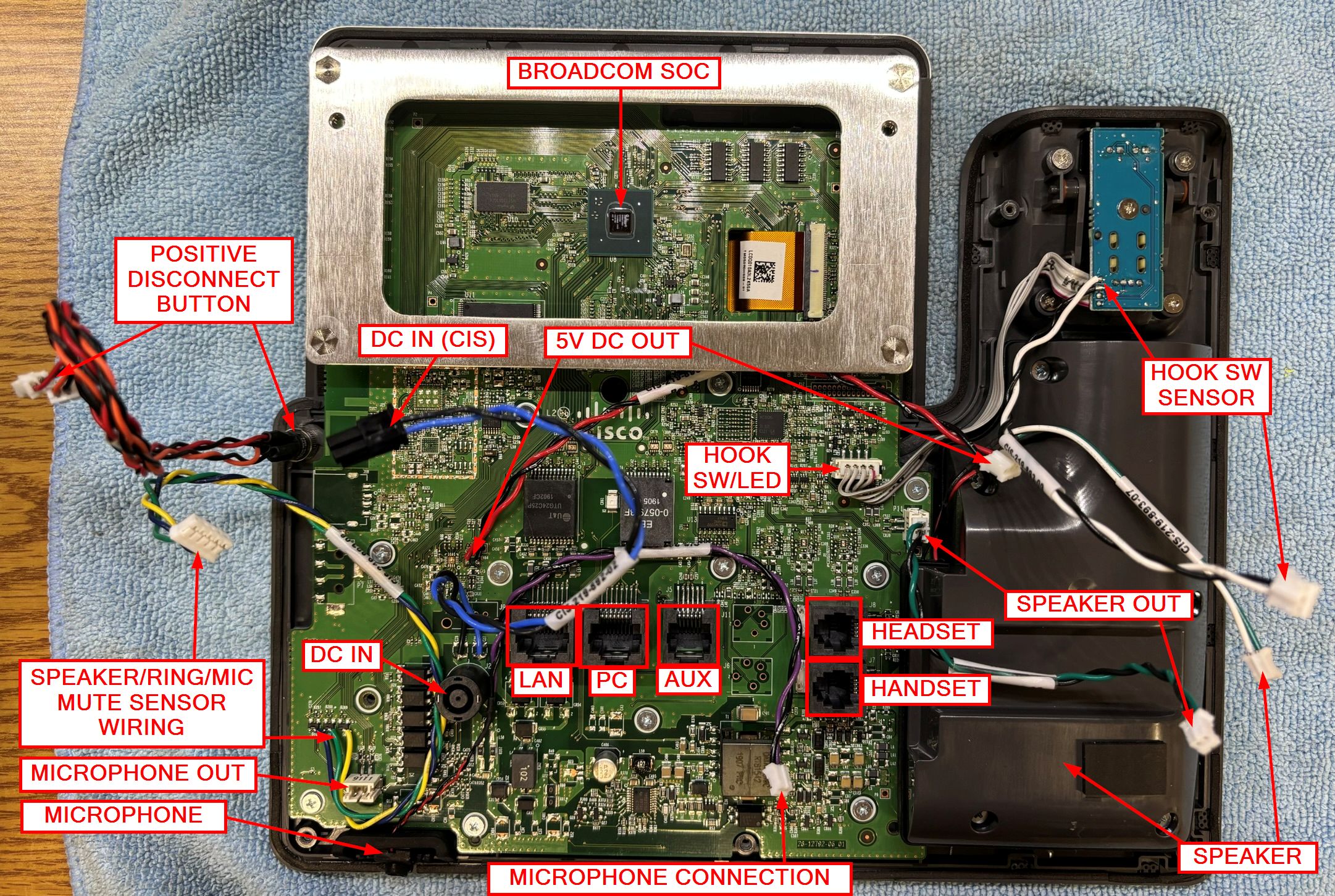
Below is an annotated image of the Cisco side of the phone. Again, this is a relatively unmodified side of a Cisco CP-8841, except with some additional wiring connections. Some connections have been extended as well. To achieve the positive disconnect functionality, several connections from the phone are passed through the positive disconnect system designed by CIS. A list of the "intercepted" connections is below, along with short descriptions:
- Built-in microphone - disconnected until manually enabled by pressing the TSG button
- Built-in speaker - disconnected until manually enabled by pressing the TSG button (unless phone is ringing)
- DC IN - extra wiring soldered to board that runs to CIS custom board with DC input jack (48 V DC)
- 5V DC OUT - Used to power positive disconnect circuitry from the phone
- Hook switch sensor - Additional connection soldered to hook switch so it can be monitored by the positive disconnect circuit
- Positive disconnect (TSG) button - Used to activate/deactivate positive disconnect feature (LED indicator to show mute state)
- Speaker/Ring/Mic mute sensor - Used to monitor speaker, headset, and software mute LEDs to control positive disconnect functionality (explained later)
- Headset port (in/out) - disconnected until manually enabled by pressing the TSG button
- Handset port (in/out) - disconnected until manually enabled by pressing the TSG button
- LAN port - connected to internal fiber media converter
- PC port - passed directly through to back casing through RJ-45 keystone jack
- AUX port - not used in this system
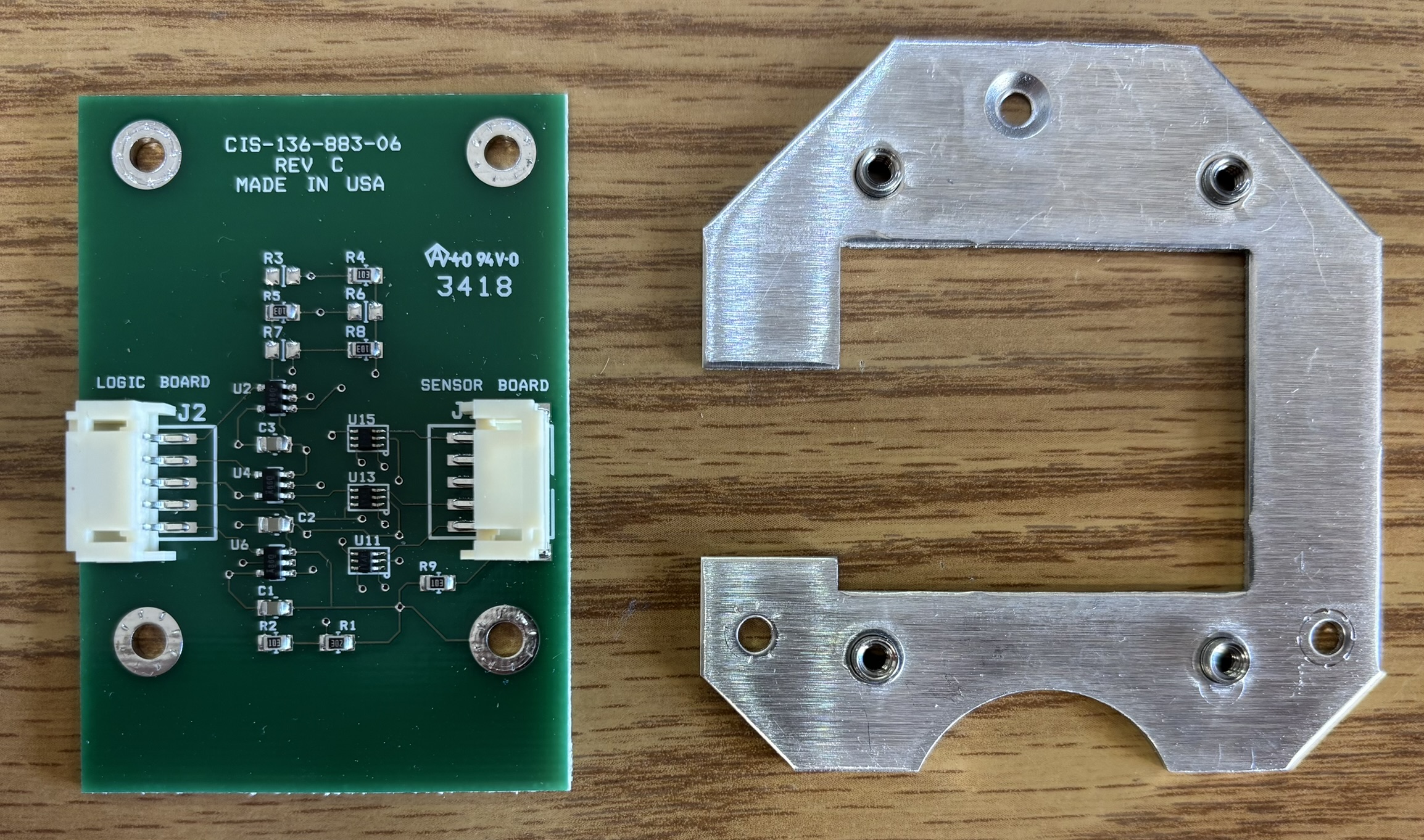
As mentioned earlier, there are several additional circuit boards contained within the phone. The first CIS-designed board we will be looking at is the sensor interface board (CIS-136-883-06). This board mounts to a custom bracket, which then mounts (via standoffs) above the fiber media converter board. The purpose of the sensor interface board is quite interesting. It monitors 3 transistors on the Cisco CP-8841 motherboard. The transistors it monitors control the speaker active, headset active, and software mute active LEDs on the keyboard. To achieve this, it uses voltage detector ICs to monitor the voltage of the transistors on the CP-8841 motherboard. This information is transmitted to the logic board for the positive disconnect system. We were originally confused by this circuit, as the positive disconnect feature is manually controlled by the TSG button and would not need to know the state of speaker, headset, etc. However what about the phone ringing? A phone is not very useful if it cannot ring, and if implemented as we originally thought, the speaker would be disconnected unless the TSG button was pressed, resulting a non-ringing phone. CIS was clever and uses this sensor circuit to monitor the speaker, headset, and mic mute LEDs. If the phone is ringing, the speaker LED does not light up, therefore the positive disconnect circuit will automatically enable the built-in speaker, allowing the phone to ring. However, if the speaker active LED is on (indicating a call in progress), the positive disconnect will interrupt the speaker connection unless the TSG button is pressed.
We confirmed this by observing the LED states during phone startup, listening for relay activity, and testing the positive disconnect function (by pressing the TSG button). When the phone boots normally, not much happens with this portion. However, activating the speaker or headset function will light up the appropriate LED, which engages the positive disconnect. The mute state can then be controlled by the TSG button. Pressing the software mute switch would cause its LED to light up, and likely trigger a positive disconnect (mute) as well, but we were not able to test that. To test this without registering the phone with CUCM (Cisco Unified Communications Manger) or a PBX, we put it into factory reset mode. This caused the speaker active and headset active LEDs to light up when they normally would not.
This board is the primary logic board (CIS-136-883-04) for the TSG positive disconnect. Using discrete logic and no central processor or MCU, it controls the positive disconnect feature. Based on several inputs (TSG button, hook switch, speaker/headset LEDs), it will make a decision to disconnect or enable all audio devices within (and connected externally to) the phone. Also, the speaker override function is controlled by this board to enable only the speaker relay when the phone is ringing. As mentioned earlier, the LED state is used to make this determination along with the small transformer mounted to the board. Based on our examination, the transformer is used to detect when audio is being played to the speaker. If the phone is ringing, based on the aforementioned criteria, the speaker relay will be energized to enable the speaker. However, if the speaker LED is on, indicating an active call, the TSG button will determine whether the speaker is enabled or disabled. Interestingly, the instruction sheet shipped with the phone mentioned that the default Cisco Chirp 1 or Chirp 2 ringtones "provide the best performance". It is likely that these two ringtones guarantee a good pickup of the signal through the transformer and related logic. There is a small grid of test points for troubleshooting and verification of functionality. The connectors on this board, along with descriptions, are listed below.
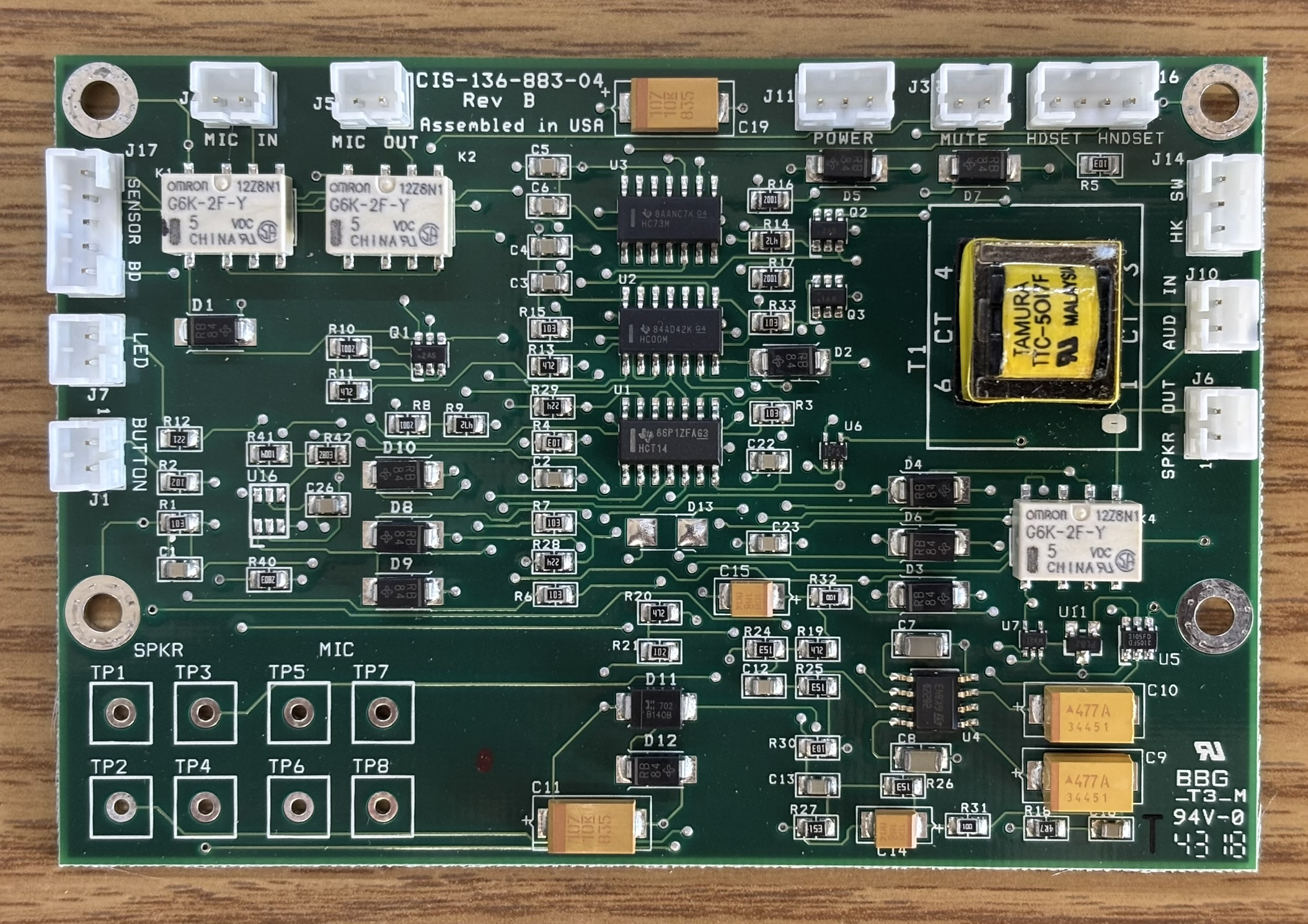
Below is a table that describes the connections on the board shown above.
| ID |
Name | Function/Connection |
|---|---|---|
| J1 | BUTTON | TSG button input |
| J3 | MUTE | Mute control for CIS external connections interface board |
| J4 | MIC IN | Goes to microphone output connector on CP-8841 motherboard |
| J5 | MIC OUT | Connects to CP-8841 internal microphone |
| J6 | SPKR OUT | Connects to CP-8841 internal speaker |
| J7 | LED | TSG button indicator LED |
| J10 | AUD IN | Goes to speaker output connector on CP-8841 motherboard |
| J11 | POWER | Goes to 5V DC output on CP-8841 motherboard |
| J14 | HK SW | Goes to Cisco hook switch sensor board to monitor state |
| J16 | HDSET HNDSET | Goes to CIS external connections interface board |
| J17 | SENSOR BD | Connects to CIS sensor board |
This is the external connections interface board for the TSG positive disconnect (CIS-136-883-05). It also includes the isolation relays (OMRON G6K-2P-Y DPDT) for the headset and handset. The 4 RJ-11 connectors are for the handset and headset to pass through the board. The purpose of this board is to completely disconnect the headset and handset using the relays. Unless activated, the relays will be open circuit, isolating the headset and handset. Upon pressing the TSG button, the relays will be energized and complete the circuit, allowing the headset and handset to work. Two of the RJ-11 connectors are exposed to the outside of the casing, this is for the user to connect the handset and headset. The internally-facing RJ-11 connectors are for jumpers to connect to the respective ports on the back of the CP-8841 motherboard. The circular DC power input jack is also on this board next to the RJ-11 jacks. It splits the 5V and 48 V DC power out to separate connectors. There is a small grid of test points for troubleshooting and verification of functionality.
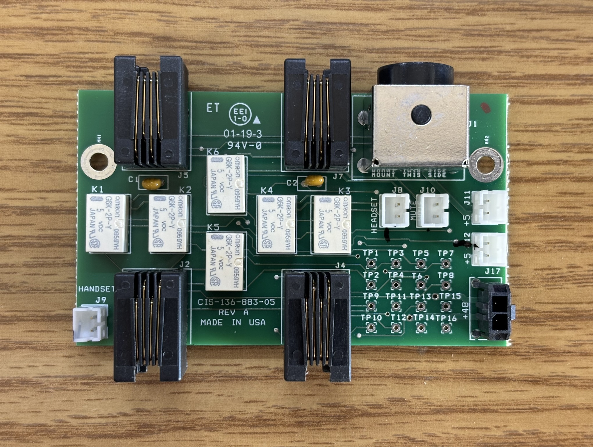
Below is a table that describes the connections on the board shown above.
| ID |
Name | Function |
|---|---|---|
| J1 | DC power input connector (48 V and 5 V) | |
| J2 | RJ-11 internal jack for handset | |
| J4 | RJ-11 internal jack for headset | |
| J5 | RJ-11 external jack for handset | |
| J7 | RJ-11 external jack for headset | |
| J8 | HEADSET | Connects to positive disconnect logic board |
| J9 | HANDSET | Connects to positive disconnect logic board |
| J10 | MUTE | Connects to positive disconnect logic board |
| J11 | +5 | 5 V DC output, connects to internal fiber media converter(s) to provide power |
| J12 | +5 | 5 V DC output, connects to internal fiber media converter(s) to provide power |
| J17 | +48 | 48 V DC output, connects internally to the CP-8841 motherboard to provide power |
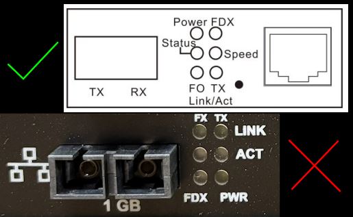
The internal fiber media converter is responsible for taking the Ethernet connection from the CP-8841 motherboard and converting it to an optical fiber interface. In this case, it's a gigabit SC fiber interface. Other models are available with different connectors and speeds. We were able to confidently identify this media converter as a CVT-3002-PLUS from Connection Technology Systems (CTS). It's an inexpensive and off-the-shelf component that CIS Secure likely orders in bulk directly from CTS. More likely than not, they order just the media converter board without the casing. Also, there is no RJ-45 jack present (and no evidence it ever was) so perhaps they special order it without the jack as well. CIS or CTS solders a short Ethernet jumper to the pads where the jack would be. The media converter uses a Realtek chipset, and the DIP switches are for defining connection settings such as auto/manual negotiation, speed, and duplex.
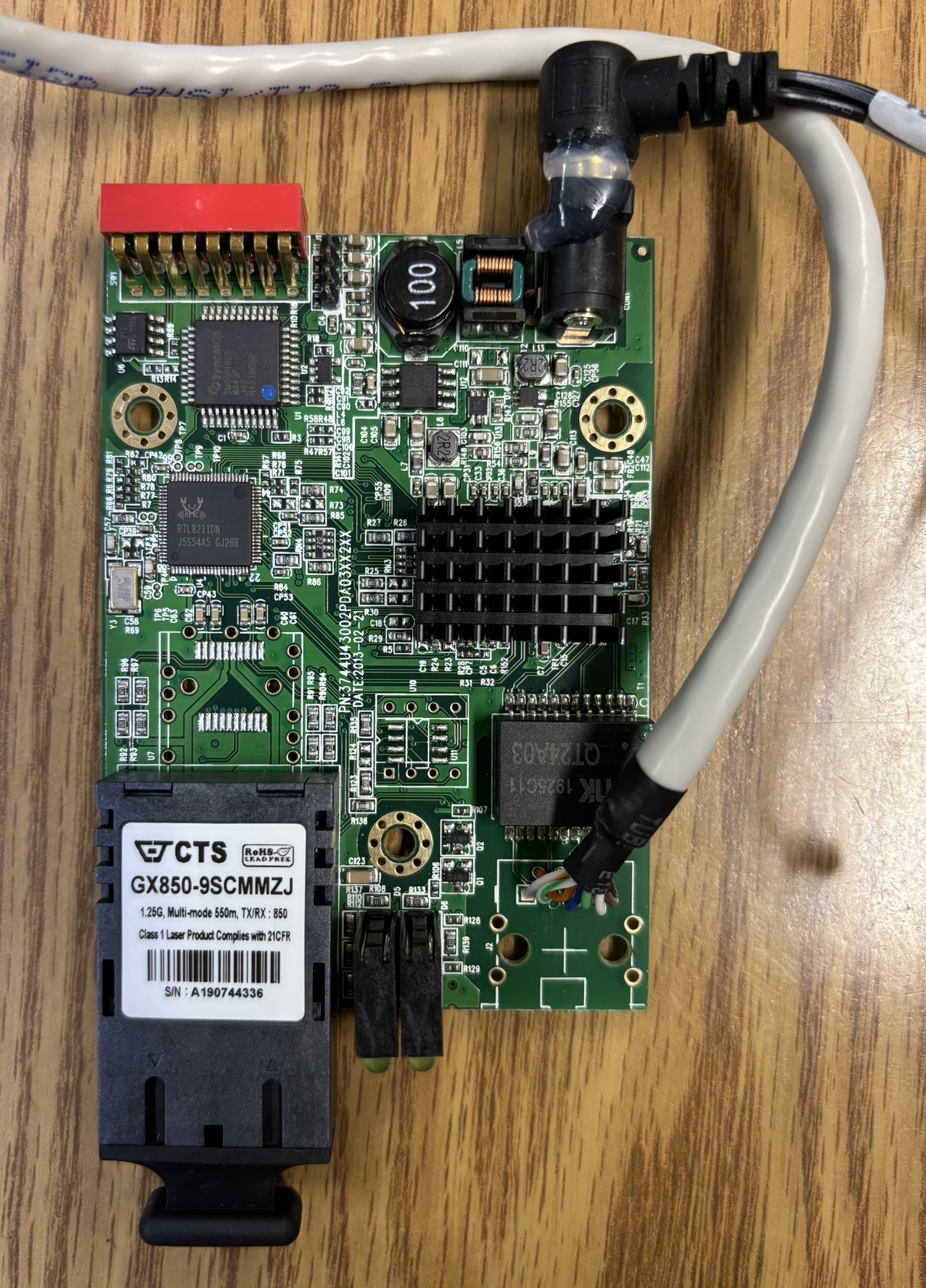
It's worth noting that the markings on the back of the casing, for the media converter status LEDs, are incorrect. We examined the user guide for the CVT-3002-PLUS and referenced the diagram to confirm this. We originally discovered this when we noticed the LED labeled PWR, flashing much like a network activity indicator would. Below is a comparison of the marking on the CIS casing and the actual LED layout of the CTS media converter. It's a small oversight, but could be confusing when verifying fiber network connectivity.
This device, overall, is quite fascinating. It was designed to solve a problem most people don't even know exists. We highly encourage you to check out the links below, especially the CNSS 5001 type-acceptance program document. It outlines the requirements and features for devices like the DTD-8841-01D1A. Also, if you want to see how much a device like this costs, check out the TSG Approved Equipment Spreadsheet from DNI.GOV, just make sure you are sitting down before reading it! It mind-blowing to see how much the government will pay for a common IP phone with some inexpensive and low-tech modifications.
- CISSecure.com - Datasheet of CIS Secure 8841 model IP phones
- CISSecure.com - Products Page
- CISSecure.com - What is TSG
- DNI.gov - TSG Approved Equipment Spreadsheet
- CNSS.gov - CNSSI 5001 - Type-Acceptance Program for Voice Over Internet Protocol (VoIP) Telephones
- RF Wireless World - Comparison of Ethernet and Fiber Optic Networking
- CTSystem.com (CTS) - CVT-3002-PLUS Fiber Media Converter Datasheet
- CTSystem.com (CTS) - CVT-3002-PLUS Fiber Media Converter User Manual