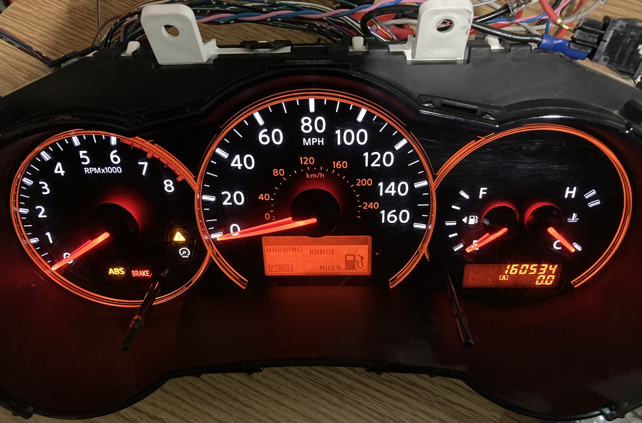
If you haven't already, check out the writeup for the Ford Crown Victoria instrument cluster as it explains some of the basics of how the instrument cluster operates and communicates with the vehicle. The goal with this project was to work with a more modern instrument cluster to enable more control through the CANbus. One issue that was faced with the Crown Vic cluster was only some functions being controllable via CANbus. The tachometer and speedometer on the Crown Vic cluster were controlled via a Ford proprietary protocol. This limits what can be done with the cluster outside of the vehicle. The Nissan Altima instrument cluster (technical documentation refers to it as the combination meter) design dates from 2008 and was pulled from a 2008 Altima, which is a bit newer than to the Crown Vic cluster which dates back to around 1999. While not all functions of the Altima cluster are controllable via CANbus, most are, and more importantly the speedometer and tachometer are. Luckily there are no proprietary protocols, so the remaining functions such as the fuel gauge and charging system indicator are controlled in an analog manner via wires on the main connector. Those can be controlled with an Arduino or something similar if desired.
CANbus commands and IDs were derived using a similar method to the Crown Vic cluster but in a slightly more optimized manner. Fuzzing/random data was sent but at a slower speed and a log was kept. When the cluster responded, the script was stopped and another script was used to step through the log history until the desired result was displayed on the cluster, the ID and command were then recorded. Some example commands and IDs are listed below. Most notably with the Nissan Altima instrument cluster was the fact that the cluster itself was sending data under 4 different CANbus device IDs instead of just 1. Additionally, certain functions on the cluster are controlled by seperate CANbus IDs despite likely originating from the same module. For example, the tachometer responds to commands sent by the CANbus device ID of 180, but the service engine soon MIL responds to ID 551, and the oil pressure MIL responds to ID 358. All of these indicators likely originate from the ECU but use different IDs for some reason. This could be due to the increased complexity of newer vehicles or just manufacturer choice, it is not completely clear why this is the case. In the case of the Crown Vic instrument cluster, each module (cluster included) had only 1 associated CANbus device ID.
| ID | COMMAND | MODULE | FUNCTION |
|---|---|---|---|
| 280 | METER | ||
| 2DE | METER | ||
| 5C5 | METER | ||
| 355 | METER |
||
| 180 | FF00000000000000 |
ECU |
TACHOMETER |
| 284 |
00000000FF000000 |
VSS |
SPEEDOMETER |
| 354 |
0000000000000000 |
ABS |
NORMAL - CLEARS ABS AND BRAKE MIL |
| 60D |
0000000000000000 |
BCM/LCM |
NORMAL - BACKLIGHT DAYTIME MODE (HEADLAMP OFF) |
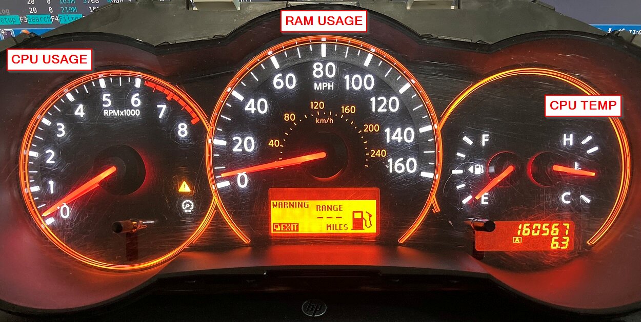
This project was taken a step further as sending arbitrary CANbus data and watching the indicators flash and gauges move was getting boring. A bash script was written to obtain system information such as CPU and RAM usage as a percentage and CPU temperature. These values are then converted to hexadecimal to be sent over the CANbus using a specially crafted command the script puts together. Some fine tuning of the gain values may be necessary depending on your system, but the script works well and can be used to have the instrument cluster display Linux system resource usage using the gauges. The tachometer displays CPU usage, the speedometer displays RAM usage, and the coolant temperature gauge displays CPU temperature. A short delay is used to prevent the gauges from shaking too much. Along with the commands to control the tachometer, speedometer, and coolant temperature gauge, additional commands are sent once per second to to turn off the warning MILs and enable the backlight to make the cluster text and gauges more visible during operation. A link to the bash script is at the bottom of this page.
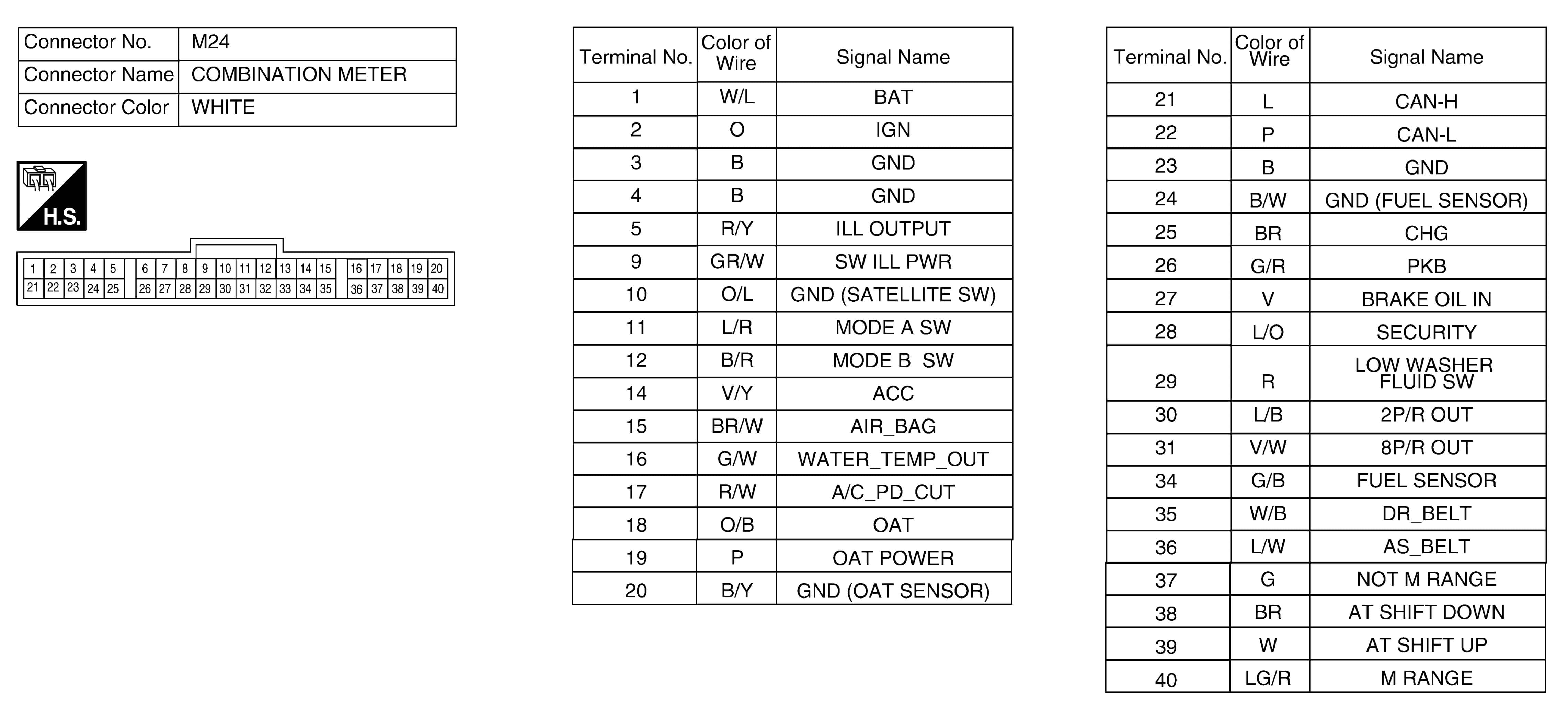
A pinout for the instrument cluster is provided below. This was pulled from the factory service manual for the 2008 Nissan Altima.
Useful links specific to this project: