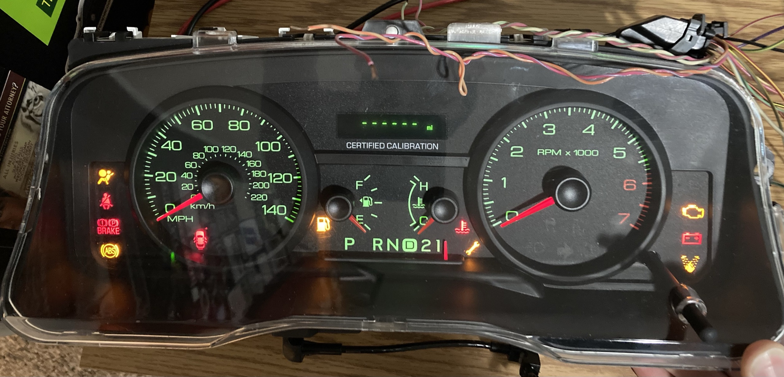
This instrument cluster was pulled from a Crown Vic at a junk yard for testing purposes. The goal is to use it to test CANbus communication methods and custom programs. Sending random and untested CANbus data into an operational vehicle is not the best idea and can be dangerous. This cluster provides a myriad of outputs such as LEDs and gauges that are perfect for testing. This cluster is interesting as it was likely from a transition period from both analog and custom digital communication methods to the standard high and low CANbus that modern vehicles use. This cluster has all of the above. Some portions are controlled by Ford's proprietary digital communication protocol called SCP. Other parts are controlled by CANbus, and some parts are controlled in an analog manner by connecting wires to ground or 12V inputs. The instrument cluster always receives 12V from the vehicle's battery and only activates when 12V is applied to specific wires, which is what would happen when the ignition is turned on. Also, the CANbus only becomes active when 12V is applied and the instrument cluster is active, the CANbus operates at a bitrate of 500,000. When 12V is first applied to the battery input, the gauges appear to "shake" for a few seconds, this is part of a self calibration procedure. Pinouts and example commands can be found below.
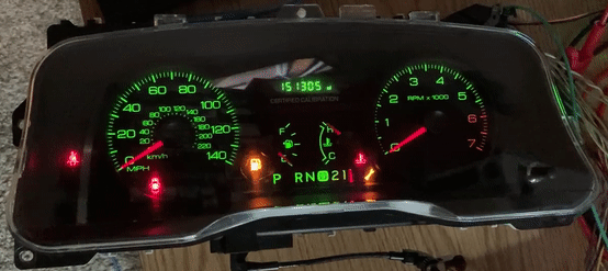
Through testing and the sending of random CANbus data combined with logging and analysis, the CAN IDs of devices on the bus can be determined based on how the cluster responds. For example, if sending random CAN data with a specific ID results in the ABS and BRAKE lights flashing on the cluster, you have likely found the ID for the ABS module. The following IDs listed below were derived this way.
- 415 - ABS MODULE
- 420 - ENGINE ECU
- 430 - INSTRUMENT CLUSTER
Below is a GIF image of the instrument cluster responding to random CAN data being sent to it. This was done with a USB to CAN adapter, can-utils for Linux, and the cangen command.
| FUNCTION (MIL/GAUGE) |
CONTROL METHOD |
|---|---|
| turn signals |
apply +12v to specific wires |
| fire suppression, airbag |
tie specific wires to ground |
| speedometer, tachometer |
SCP |
| check engine, ABS, battery, coolant temp, service, check gas cap |
CANbus |
| COMMAND | RESULT DESCRIPTION |
|---|---|
| 415#0000000000000000 |
DISABLES ABS AND BRAKE MIL |
| 420#0000000000000000 | ENABLES ODO, DISABLES CHECK ENGINE MIL, DISABLES OVER TEMP MIL, DISABLES SERVICE MIL, DISABLES BATT MIL |
| 415#6C70DB47A1543B4E | FAST FLASHES ABS AND BRAKE MIL |
| 201#E8F55D46E445C876 | GAUGE SWEEP |
| PIN |
COLOR |
FUNCTION |
|---|---|---|
| 1 |
GRN/YEL | +12V CONSTANT BATT |
| 2 | PNK/ORG | LOGIC GROUND |
| 3-5 | ||
| 6 | WHT/RED | OIL PRESSURE INDICATOR |
| 7 | ||
| 8 | VIO/WHT | BRAKE INDICATOR |
| 9 | ||
| 10 | GRN/RED | FIRE SUPPRESSION INDICATOR |
| 11 | ||
| 12 | BLK/YEL | RESTRAINTS CONTROL INDICATOR / AIRBAG INDICATOR |
| 13-16 | ||
| 17 | GRY/YEL | +12V RUN |
| 18 |
BLK | CHASSIS GROUND |
| 19 | RED/YEL | +12V START OR RUN |
| 20 | TAN/ORG | SCP + |
| 21 | PNK/BLU | SCP - |
| 22 | WHT/BLU | RIGHT TURN INDICATOR |
| 23 | GRN/WHT | LEFT TURN INDICATOR |
| 24-25 | ||
| 26 | YEL/WHT | FUEL LEVEL |
| 27 | BLK/ORG | FUEL LEVEL RETURN |
| 28-29 | ||
| 30 | WHT/GRN | HS CAN + |
| 31 | PNK/GRN | HS CAN - |
| 32 |
Useful links specific to this project: