This control panel is used to switch between operating modes of the GMK-1A system, adjust for lateral compensation (based on earth's rotation), compensate for gyroscope deviations, adjust heading, and test the system.
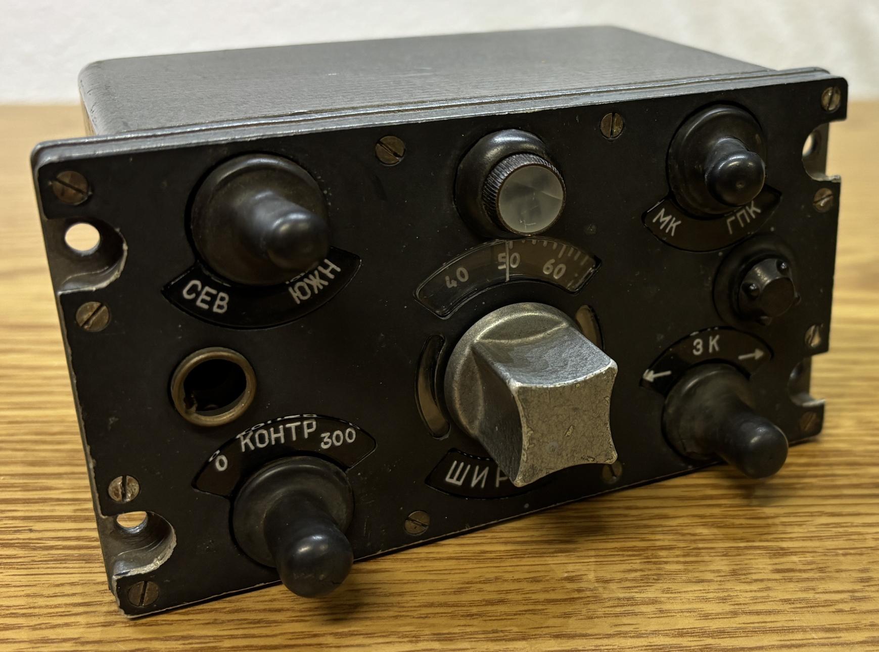
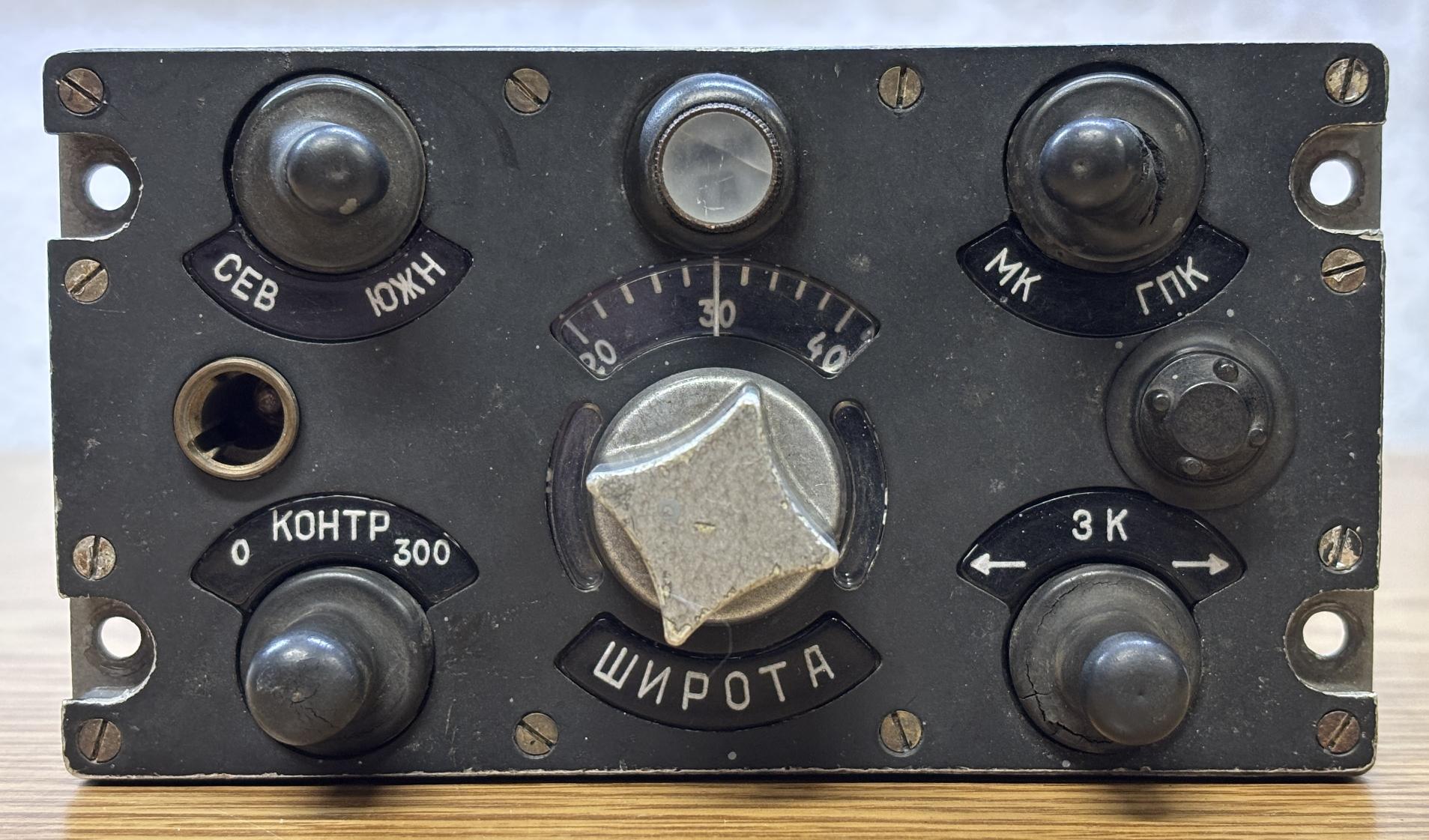
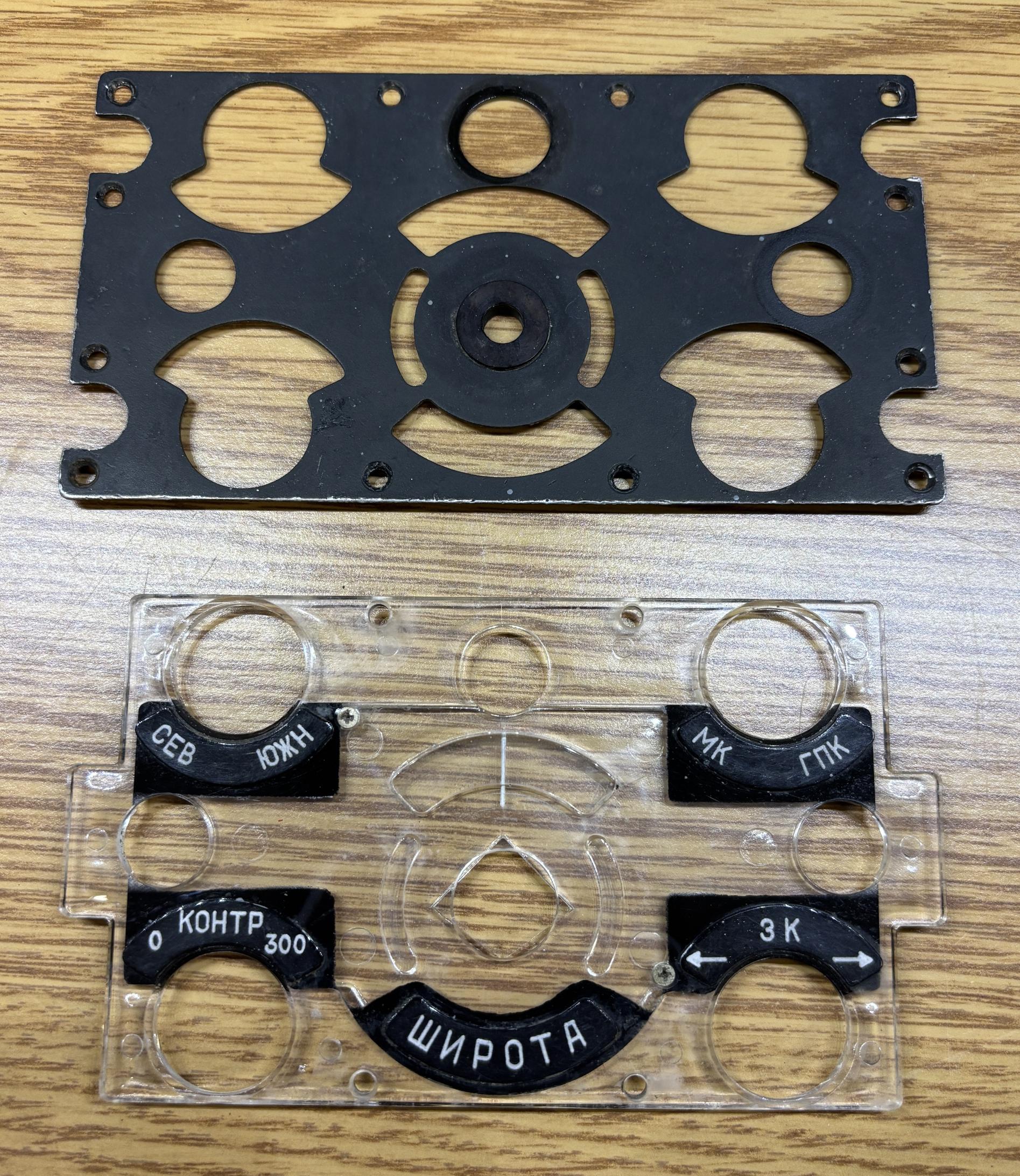
It's small metal enclosure with a hammered metallic finish on the sides and back. On the front are several switches, a potentiometer, and an illuminated panel to make the test readable at night. The descriptions of the controls originated from a translated manual for this system and have been provided below:
- TOP LEFT - Toggle: North/South hemisphere selection for latitude correction
- TOP CENTER - Indicator: Warning indicator lamp
- TOP RIGHT - Toggle: MK/GMK selector for gyroscope mode or magnetic correction mode
- CENTER - Potentiometer: Latitude setting
- BOTTOM LEFT - Momentary toggle: Test function selector?
- BOTTOM RIGHT - Momentary toggle: Course adjustment?
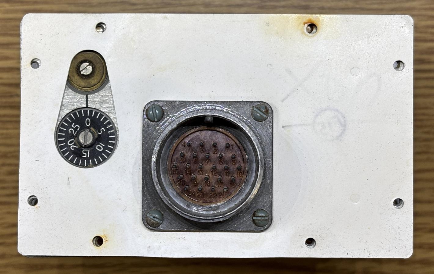
On the back of the unit are several stamps and an information plate along with a large circular connector. Several slotted screws hold the cover in place, one of which is covered with some brittle tamper-resistant compound.
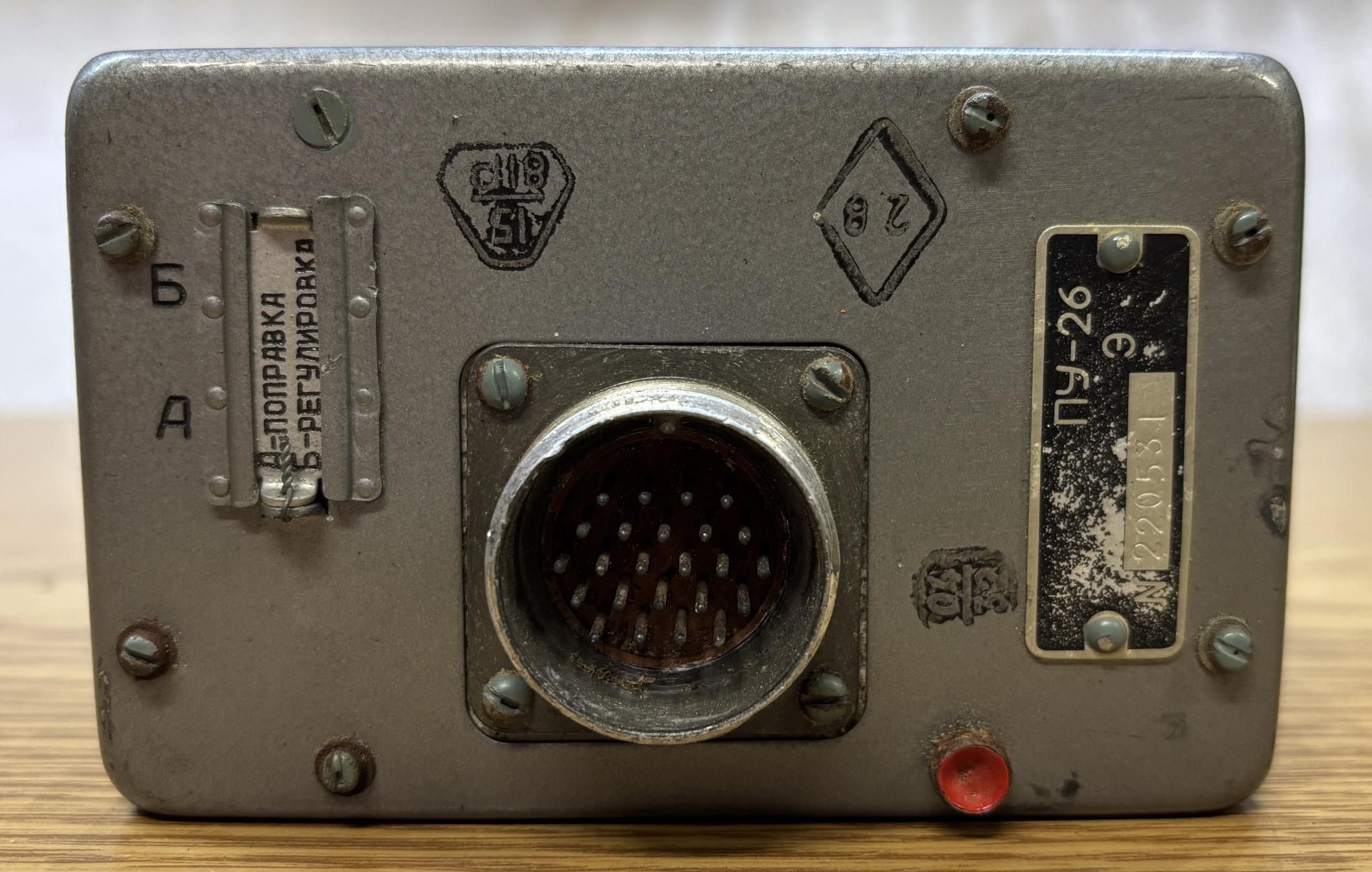
With the cover removed, a small access slot is visible. This is behind a removable metal plate on the back of the unit and provides external access to some adjustments.
A white rubberized separator is sandwiched between the inner frame and outer cover. On the left are two adjustment screws that can be accessed externally once the metal plate is slid away. The electrical connector has 24 pins.
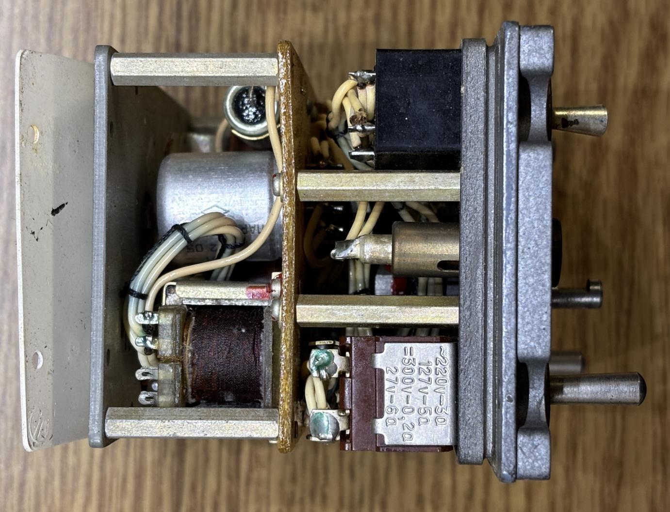
Taking a look inside the unit, we can seem some vintage soviet wiring, switches, and components.
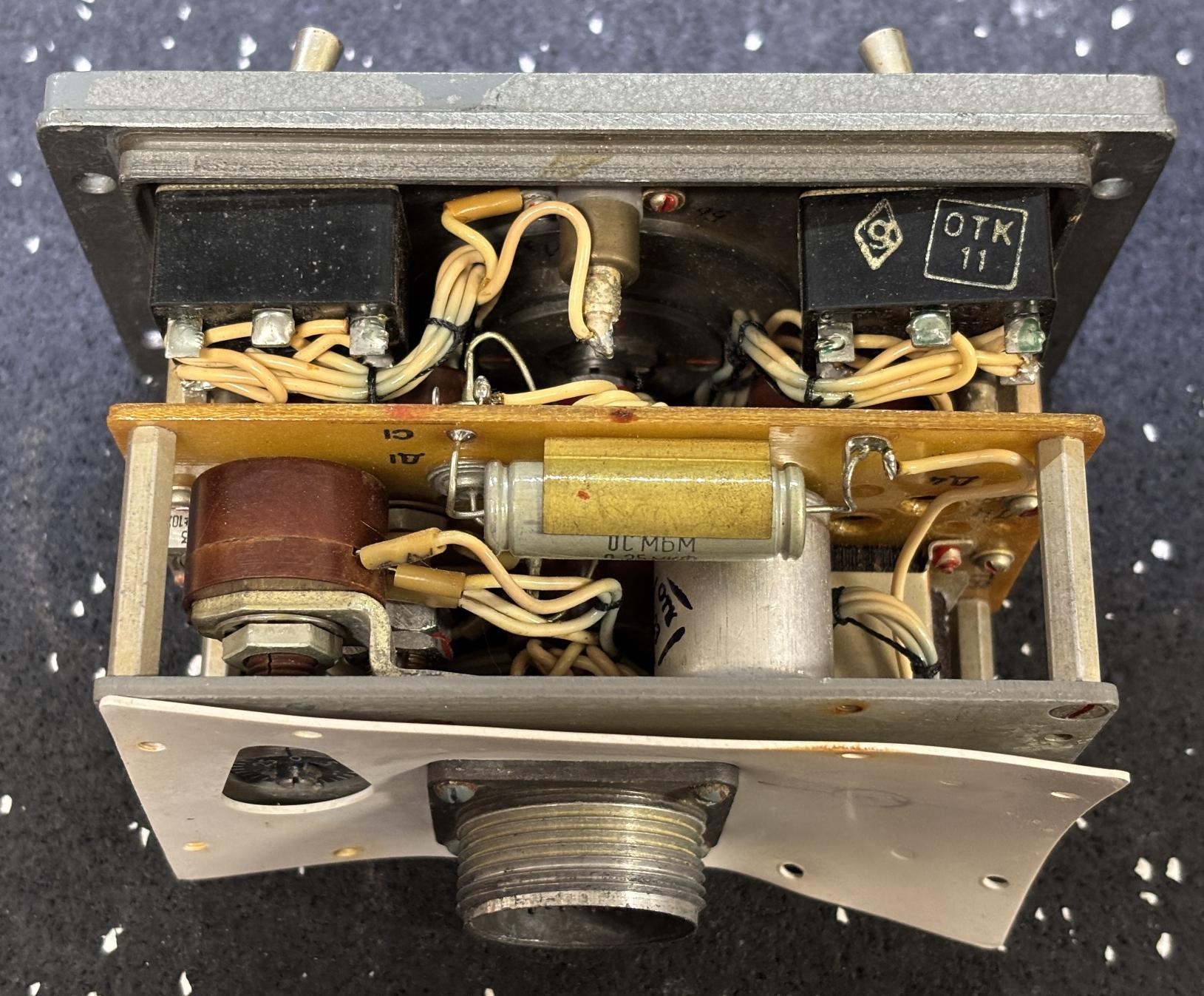
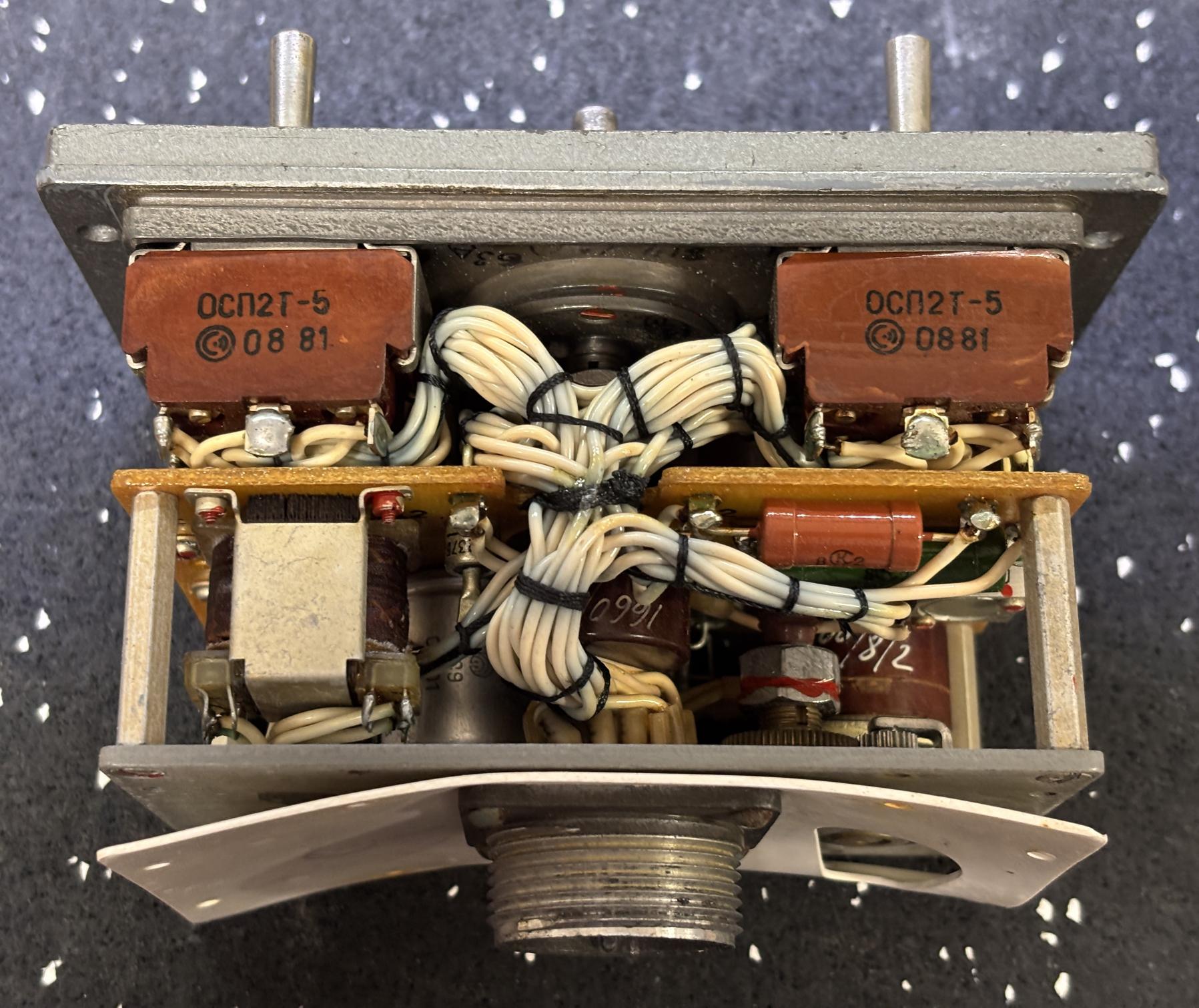
There's no active circuitry within this unit, just some capacitors, transformers, switches, and potentiometers. The toggle switches have date codes from 1981.
All connections appear to be directly soldered. The diamond symbol on the capacitor on the left is typically found in Russian mil-spec, defense, or high-reliability electronic components.
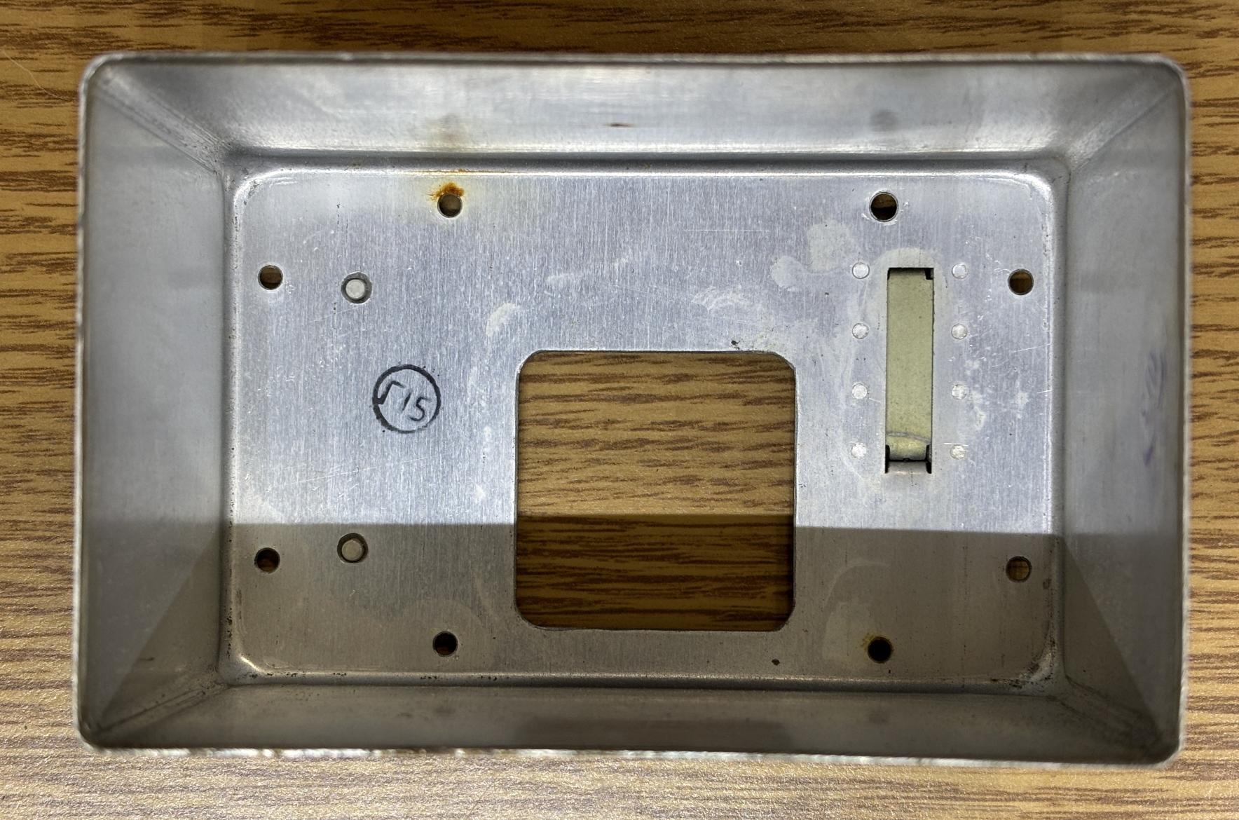
This is the front of the unit with all components stripped away, revealing the switches and mounting rings, incandescent lamp holders, and the latitude potentiometer and attached scale card.
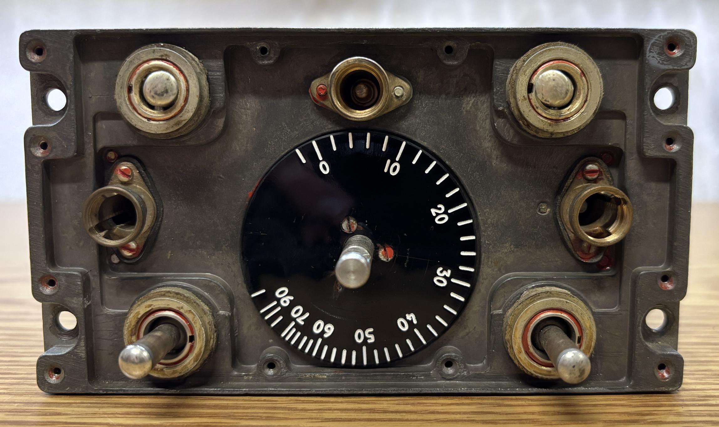
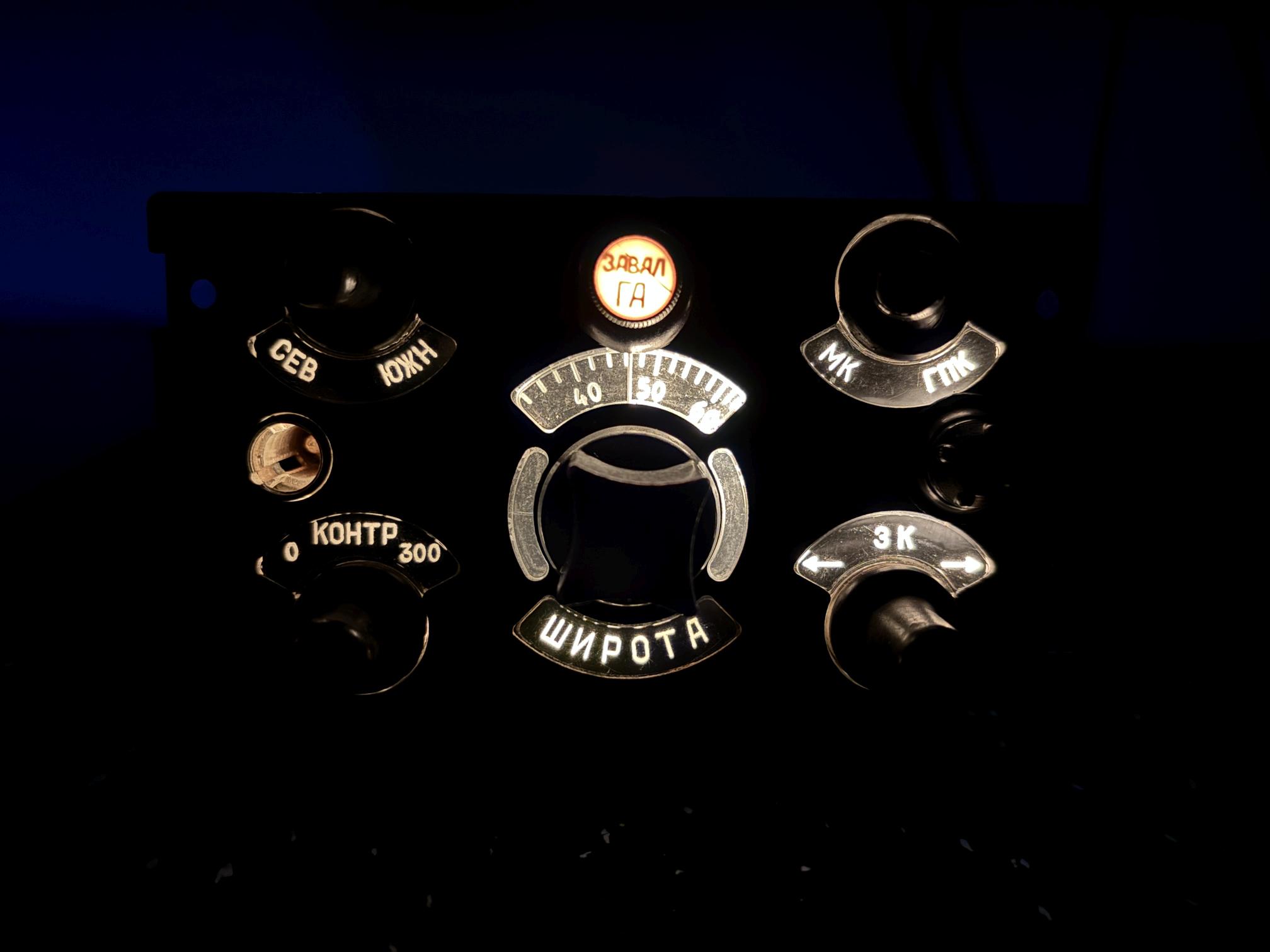
A plastic legend is illuminated by two incandescent bulbs installed in sockets on either side of the front. That is the covered by a metal overlay which is then secured by several small slotted screws around the perimeter.
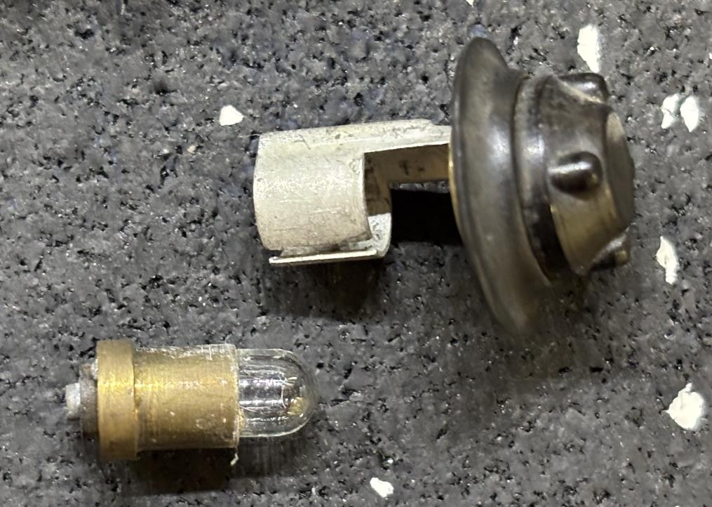
Here is one of the lamp holders. It accepts a very small incandescent bulb that is powered by 28V DC. Unfortunately, one of the lamp holders was missing from our unit. We should be able to source a replacement from a similar panel.
Here is an image of the panel brightly illuminated in a dark room, along with the top warning indicator.