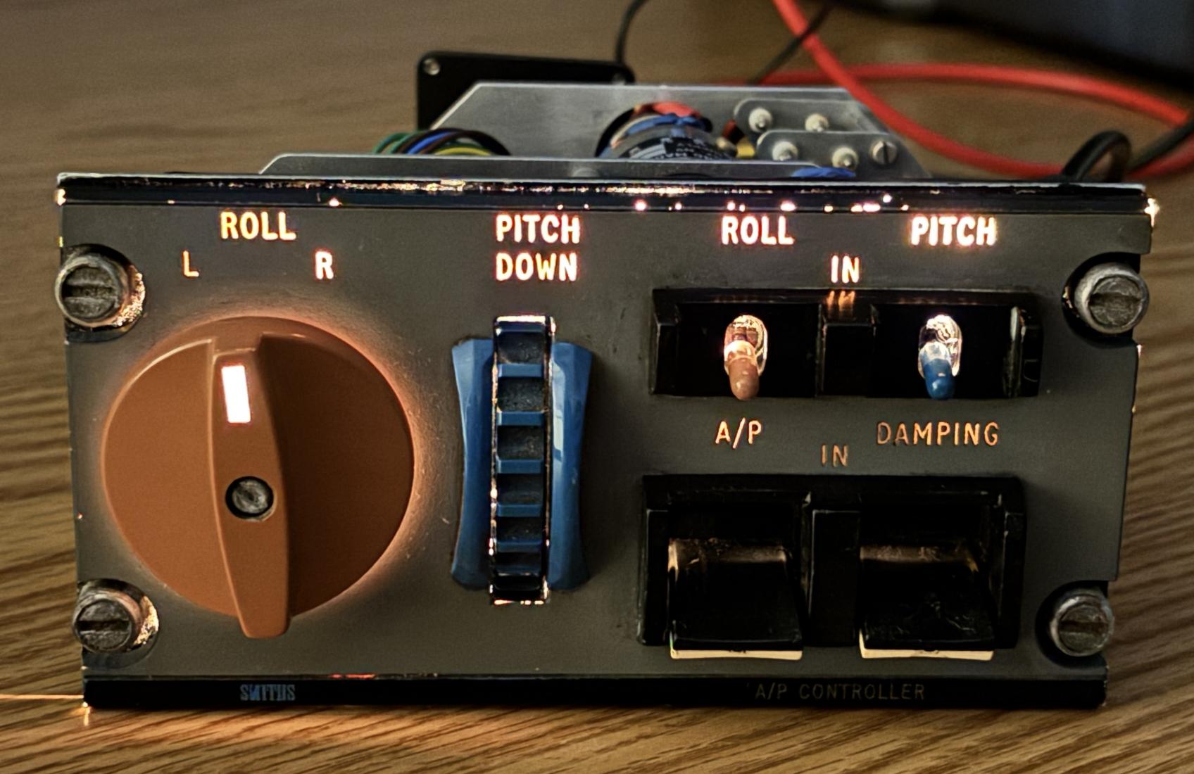
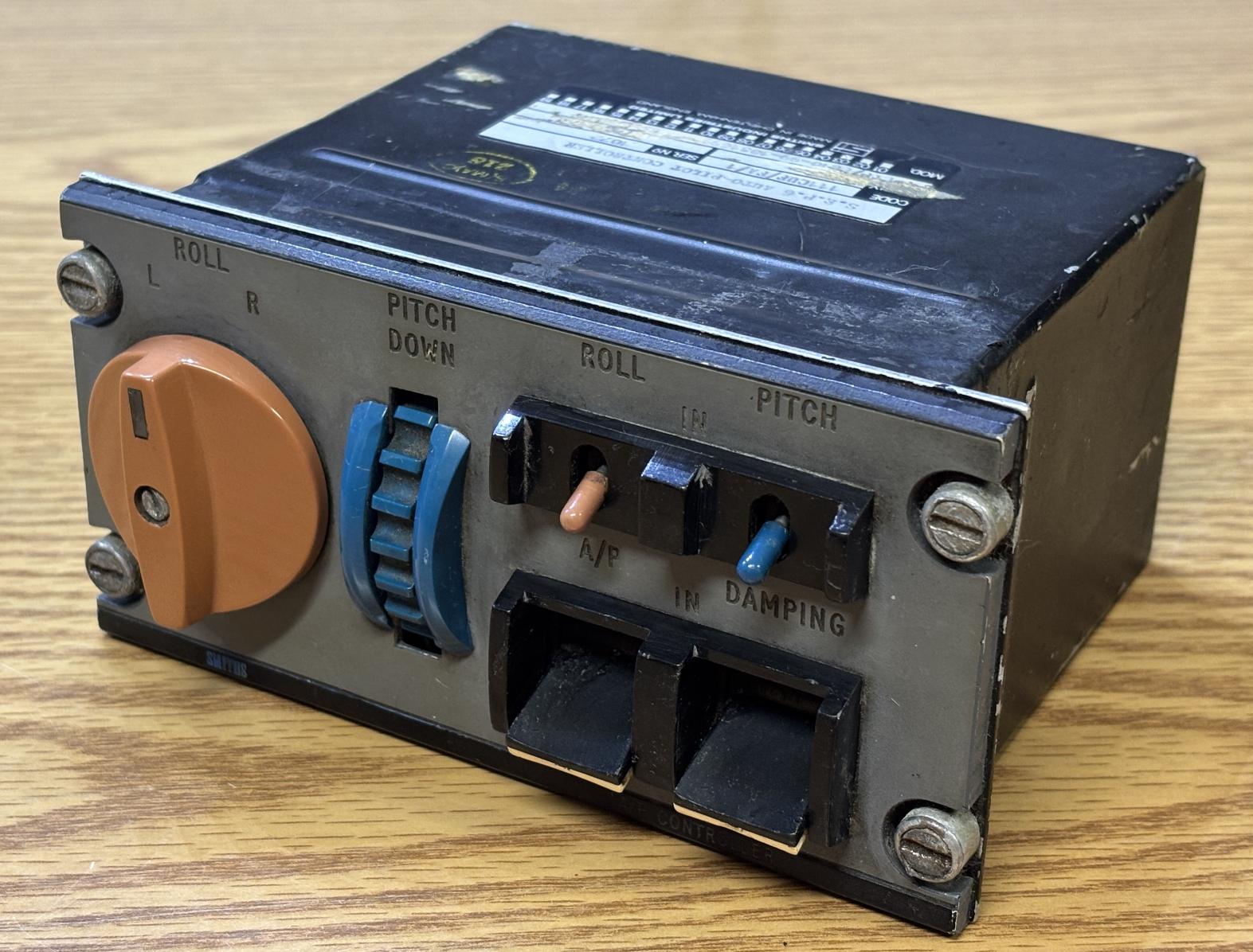
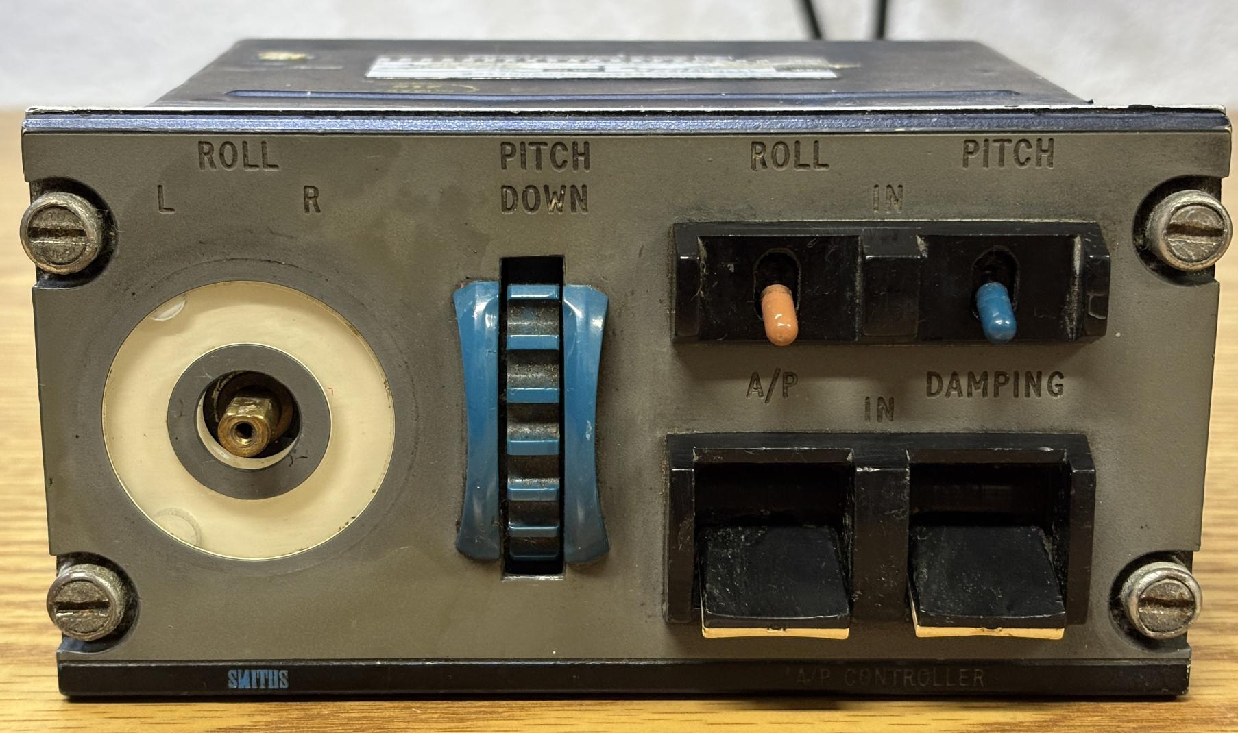
This is a Smiths Industries SEP6 autopilot controller. It would have been installed in the cockpit of aircraft models such as the Fokker F28. It is only a control head with a rotary dial for adjusting the roll, a wheel for adjusting pitch, two toggles for selecting which autopilot features are desired, and two additional toggles for enabling the autopilot as well as the damping function. There is no logic or digital circuitry contained within this unit. It would have most likely connected back to an autopilot computer elsewhere in the aircraft.
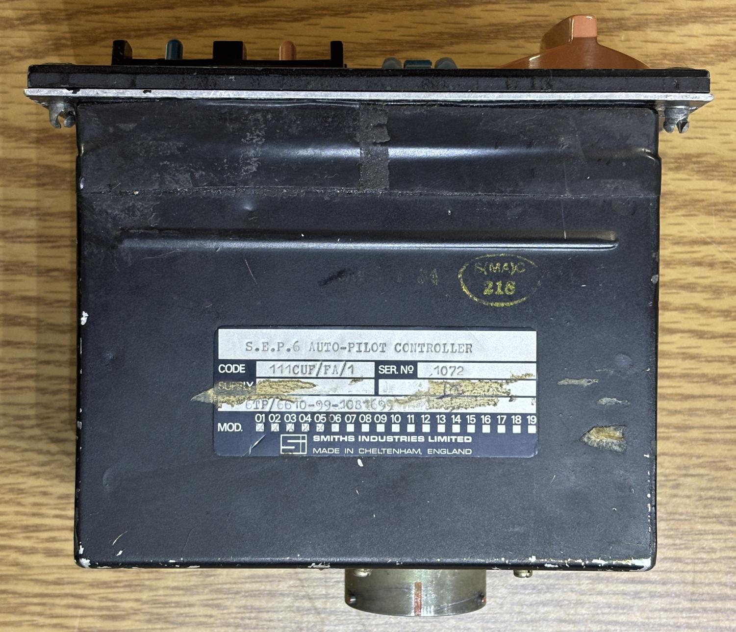
On the top of the unit is a metallic information label that describes it as a S.E.P.6 AUTO-PILOT CONTROLLER. It has a CODE of 111CUF/FA/1 and a serial number of 1072. There is a longer part number that reads 6TP/6610-99-1081699 along with some modification record stamps. There is some sort of yellow stamp on the top of the casing that we can't quite make out.
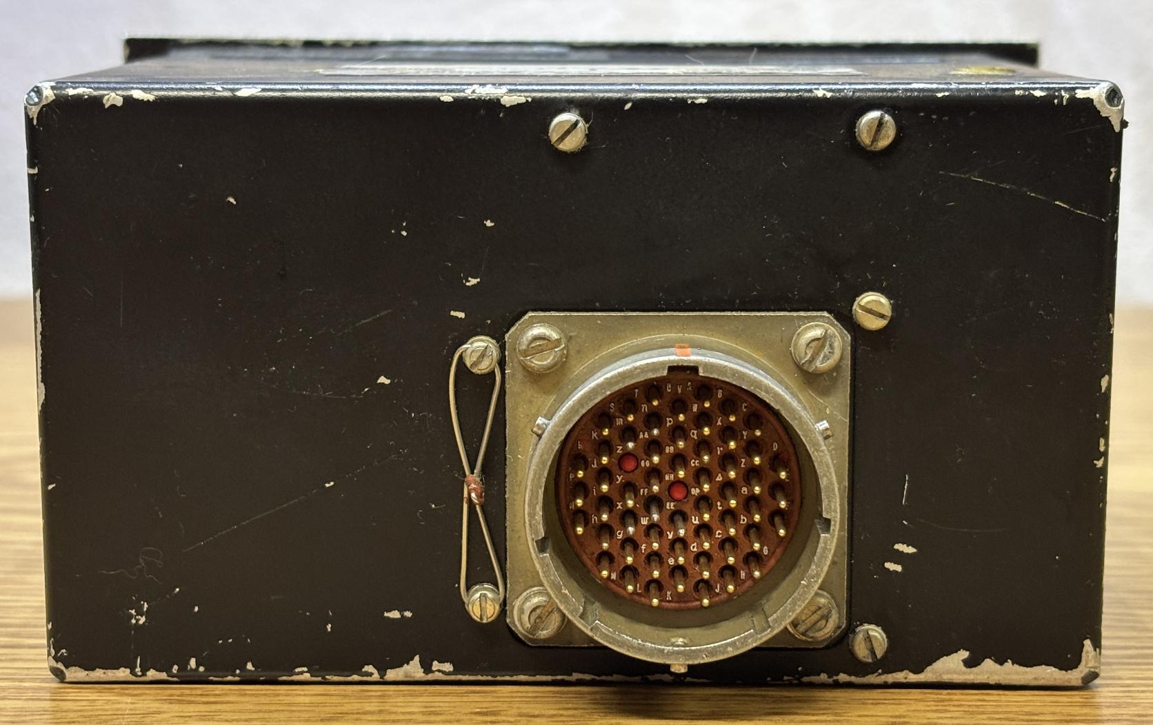
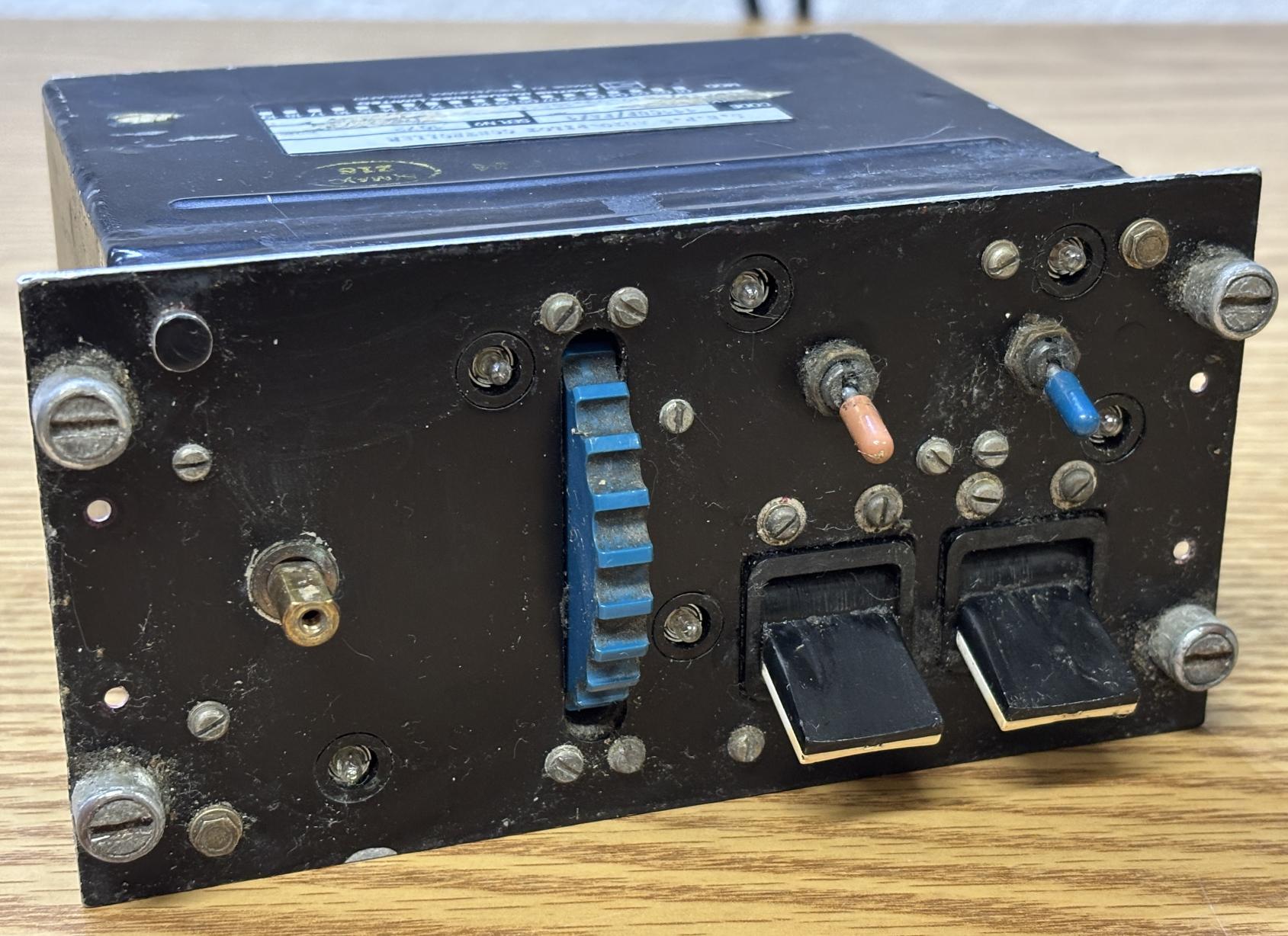
It's a pretty basic aluminum enclosure with the same mounting setup that commercial and military aircraft use for cockpit panels. On the back is one large circular connector with 55 pins, some are unpopulated. There is some safety wire routed through a couple of the slotted screws.
Removing the roll control dial reveals a transparent section of the plastic faceplate, which is illuminated from behind for visibility at night. This panel was in pretty rough shape with the dial partially broken and lots of dirt caked on the unit from years of use or poor storage conditions. We didn't bother fully cleaning this unit since it was slated for full disassembly and parts harvesting.
The illuminated faceplate can be removed after undoing four slotted screws from the back (2 on each side). This revealed even more dirt and dust that had made its way behind the plastic panel and between the switches.
Removing several slotted screws from the front and back allows the back casing to slide away from the internal frame.
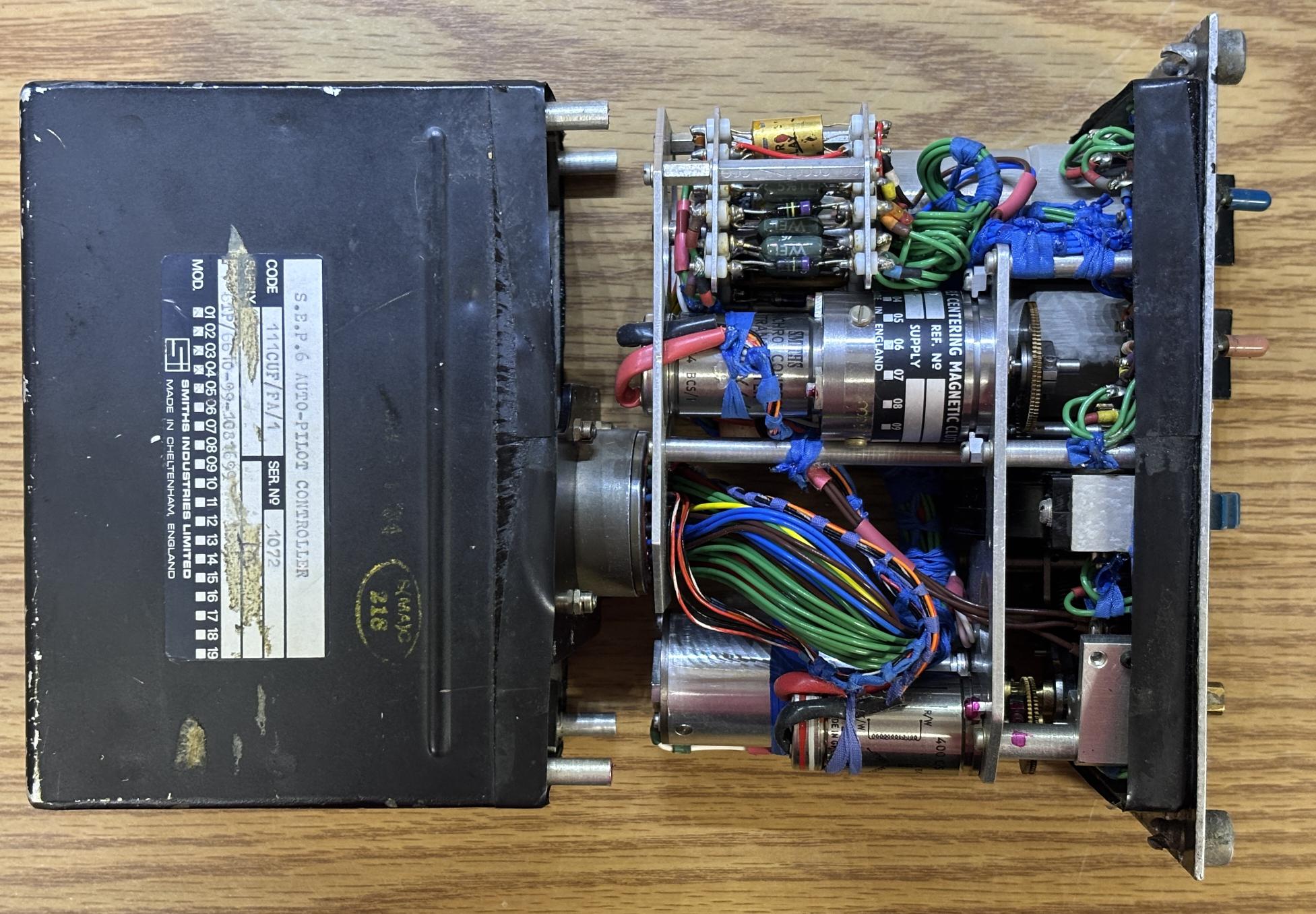
This revealed an absolute work of art in terms of avionics wiring and classic electromechanical design. The core principles of this control panel are centered around a complex set of gears along with two synchro transmitters and some electromagnetic clutches. Nearly all the connections route to the back connector, but some connect to a distribution module inside.
The wiring is quite well organized, despite the tightly packed interior.
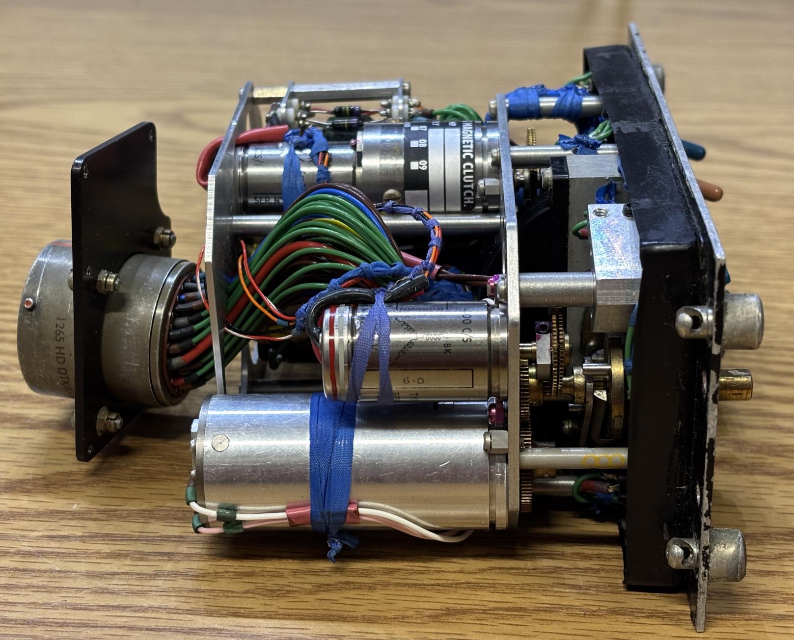
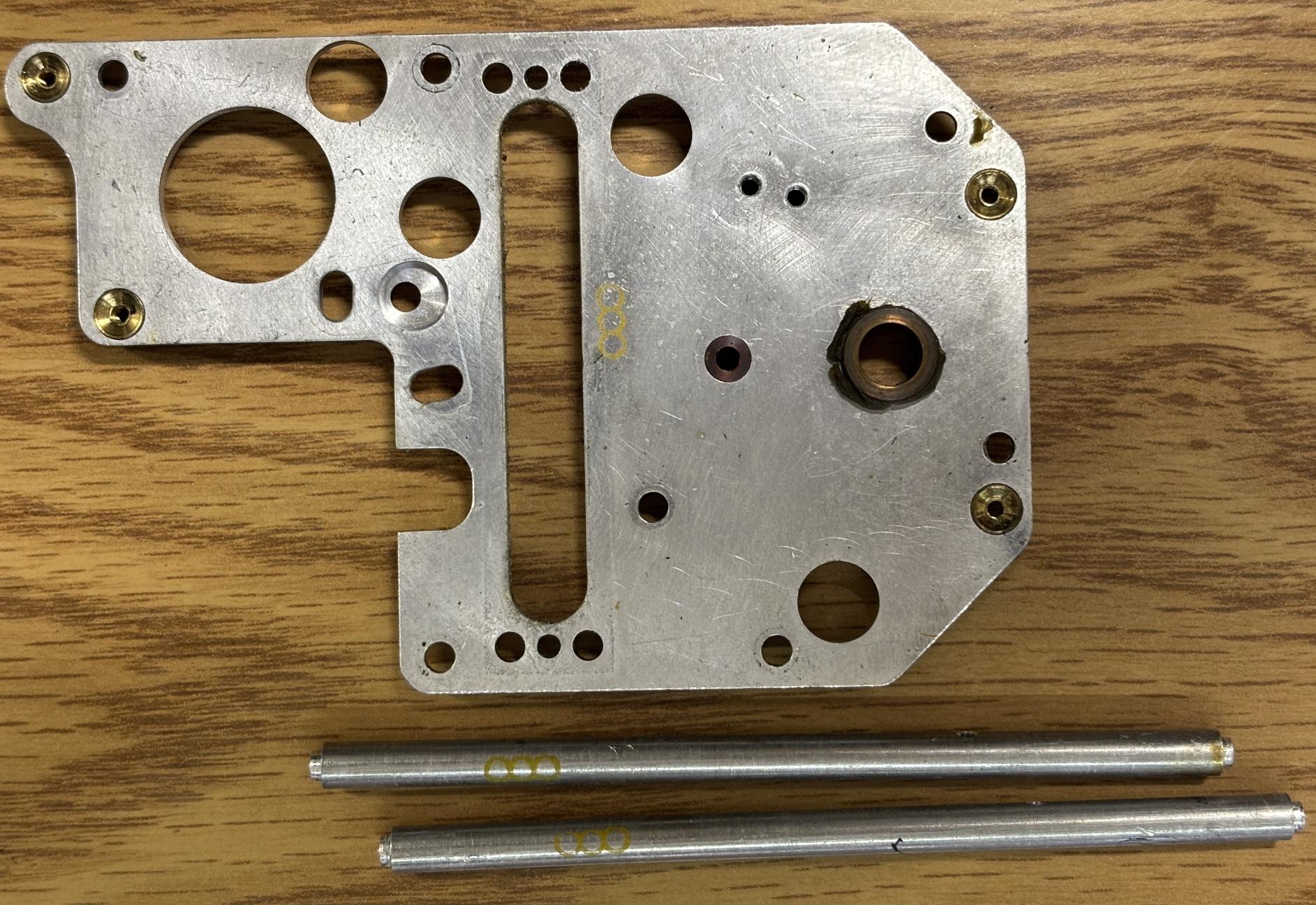
All components are mounted to different layers of metal plates, all of which are attached via metal standoffs. The whole assembly is secured to the front panel by several slotted screws.
On the left are two specialized switches that we'll discuss later. These are used to engage/disengage the autopilot and damping function. The cylinder on the right is a spring-loaded, electromagnetic clutch mechanism. When unpowered, the shaft can be rotated about 90 degrees in either direction and springs back to center when released. When powered, it is difficult to rotate but retains its position.
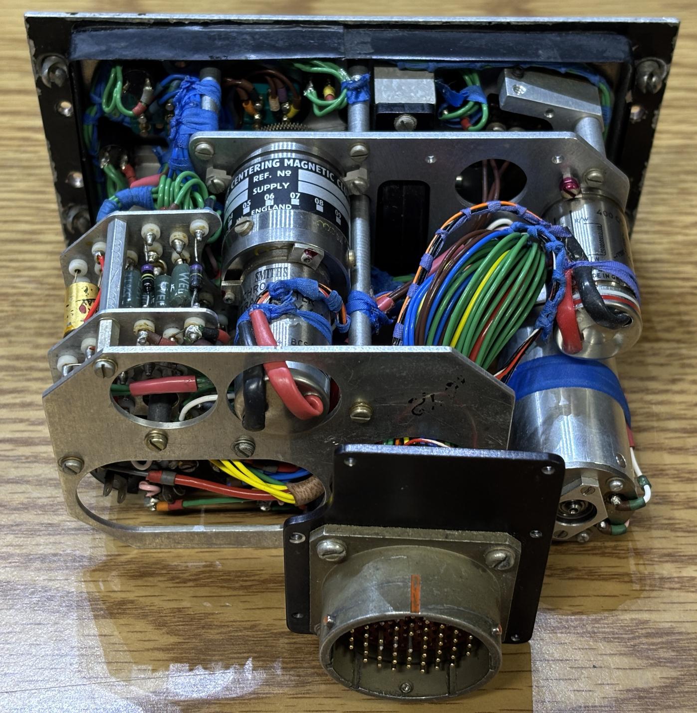
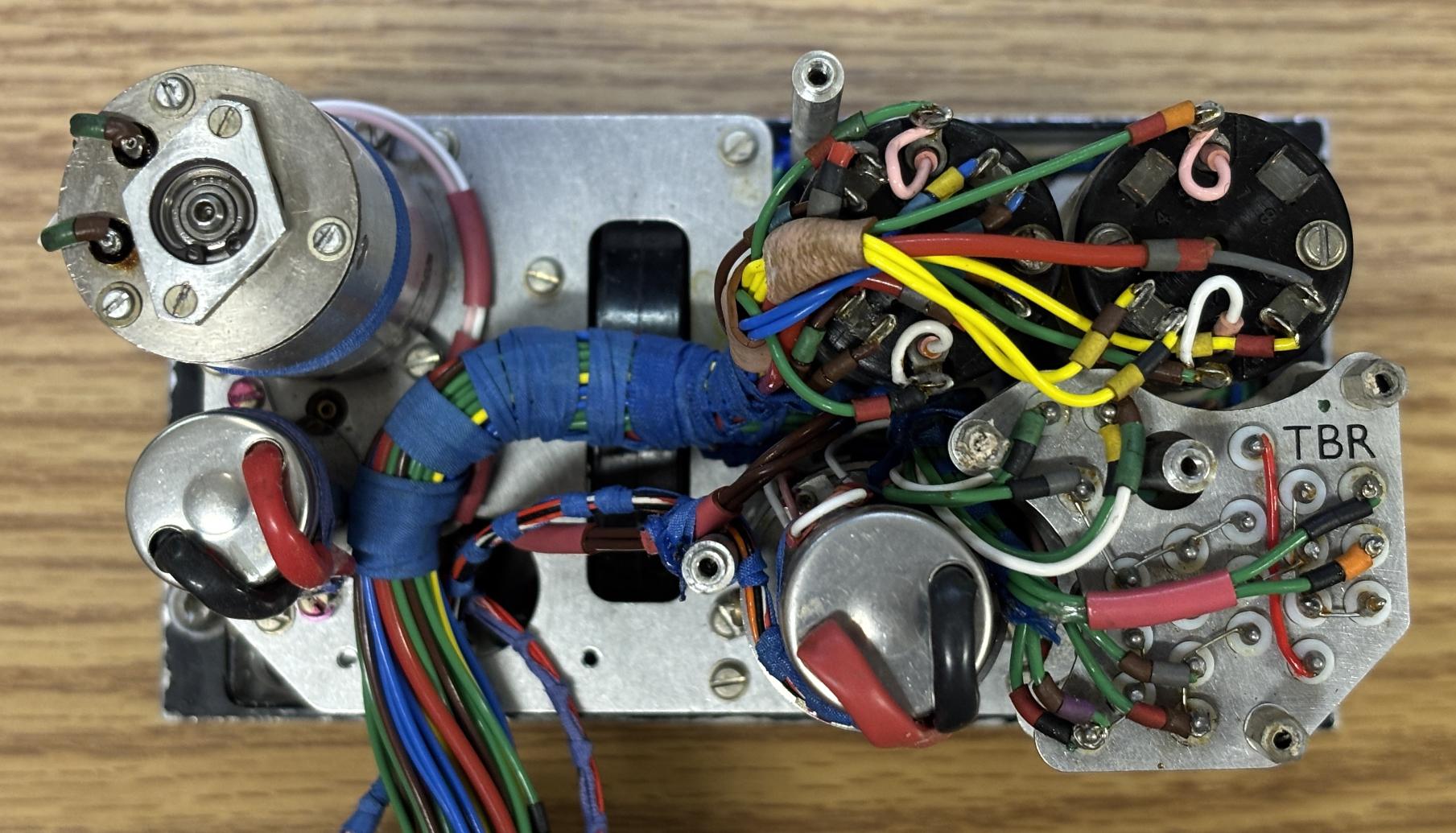
This is the back of the unit with the rear metal plate removed and connector moved out of the way. It shows the precise wiring and the electrical connections to each component.
This is the distribution module, basically an over-engineered circuit board constructed using two metal plates and some solder-mounts. Contained between are several resistors, some of which seem to be connected to the backlight bulbs, and two cylindrical, gold relays. This is a relay package that we've never seen before. They are hermetically sealed, single-pole, and the coil actuates with 14V DC but we are unsure if they are designed for 28V.
Separating the inner assembly from the front panel reveals the wiring and lamp holders for the incandescent panel illumination system. The lamps are wired in some sort of series-parallel arrangement.
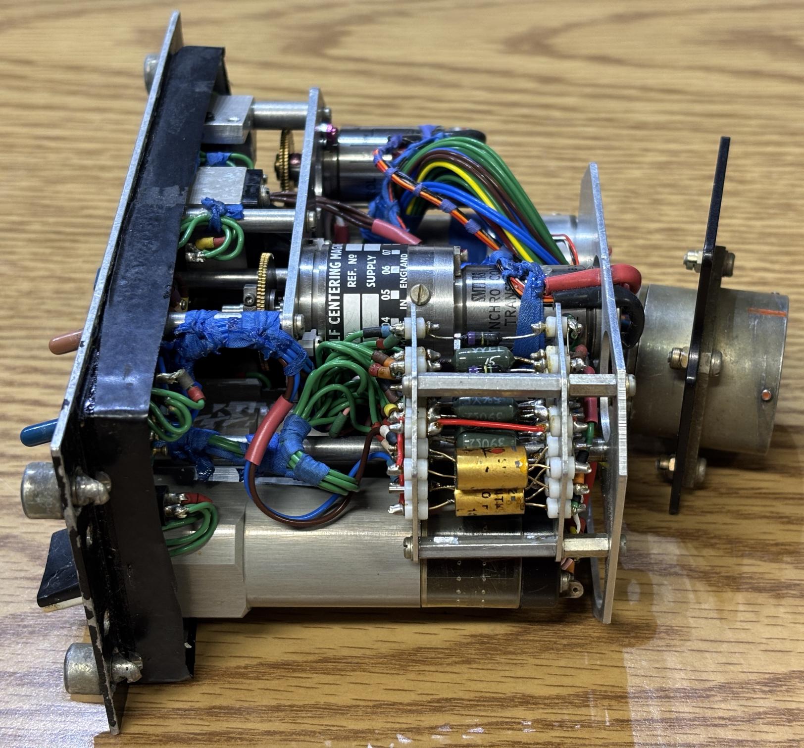
This is the core of the electromechanical mechanism. When using an autopilot, is may be necessary to manually adjust parameters such as the roll and trim. This mechanism has two independent sections, one for roll and one for pitch trim. The blue wheel is the pitch down adjustment and turns a worm gear when rotated. This operates a gear-reduction arrangement which then spins a synchro transmitter in either direction. The synchro transmitter is coupled to a self-centering magnetic clutch. This is likely for resetting the adjustment when the autopilot is disconnected.
Here is a view of the back of the electromechanical assembly, with all other components removed. Each synchro has its own set of connections along with the electromagnetic clutches.
The other section of this assembly is the roll adjustment. Turning the orange dial on the front panel rotates a shaft which is coupled to a center detent mechanism along with a micro-switch for monitoring. There is a standalone synchro transmitter which is used to report the roll adjustment position to the computer. Above the synchro is a spring-loaded electromagnetic clutch/dampener mechanism. We couldn't find much information about this part. When unpowered, the shaft can be rotated roughly 90 degrees in either direction and springs back to the center when released. This is coupled to the dial on the front, so the behavior is the same. The roll control dial will spring back to the center position unless the clutch/dampener is energized. When energized, the dial and shaft can be rotated with a decent amount of resistance while retaining the position. Like the pitch control mechanism, this seems to be a way for the controller to reset its position when the autopilot is disconnected or in the event of a fault. Nowadays this would be handled with digital logic, some buttons, and indicators. This mechanism seems quite rudimentary when compared to modern autopilot systems, but it was certainly state-of-the-art back in the 70s-80s.
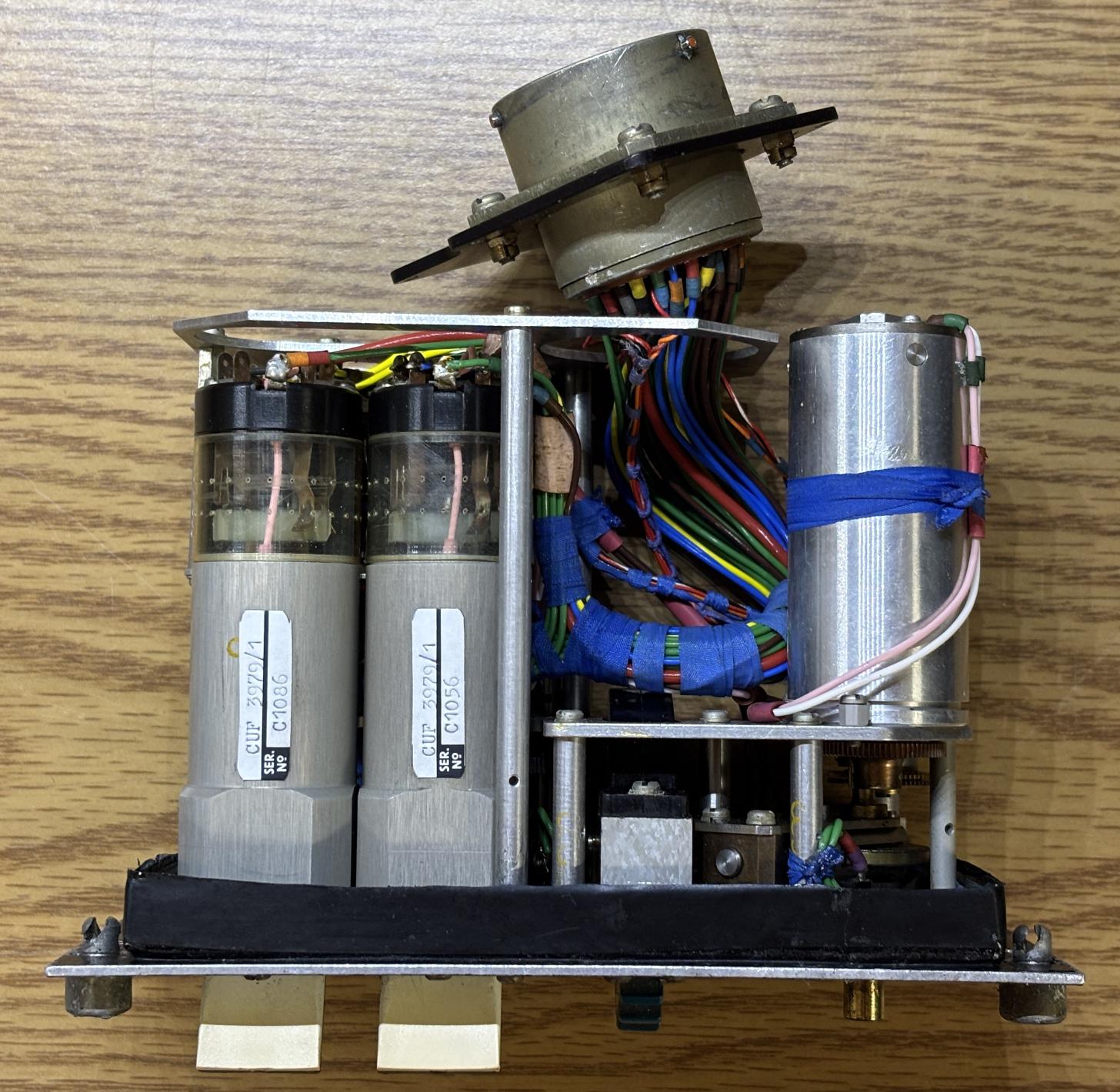
This is arguably one of the most interesting components within the device. This is an electromagnetic latching switch. The only marking other than the serial number reads CUF 3979/1. When unpowered, the switch is momentary and springs back to the default position when released. However, when a small internal electromagnet contained within the switch is powered with 14-28V DC, the switch becomes a latching toggle and can be moved from either position while retaining its state. If the switch is in the "ON" position and power is removed from the electromagnet, the switch will spring back to the default "OFF" position. The switch has two pairs of NO/NC contacts for a total of four contacts within. These contacts are visible through the transparent plastic sleeve. Two of these switches were installed within this autopilot controller and will surely be useful for a future project.
Below is the mechanism mostly torn down. The blue wheel for pitch control is a separate module that can be removed from the plate. A small micro-switch is mounted to the middle plate which provides monitoring of the roll adjustment dial when it is moved out of the center detent.
Our main goal was to harvest these two synchro control transmitters. The price we paid for this unit was less than the cost of one similar synchro on eBay, not to mention all the other useful parts we were able to salvage. Both synchros are powered by 26V AC 400Hz. One of the synchros is attached to a self-centering magnetic clutch.
An interesting detail that we noticed was three circles (OOO) painted or stamped on nearly all the metal, structural components. Perhaps this is a manufacturer marking or a designation that they are certified defense/aerospace parts.
Since this was a full disassembly, we clipped the wires for the incandescent backlight bulbs and powered them directly with about 12 volts. The poor condition of the faceplate leads to a relatively unimpressive illumination display.