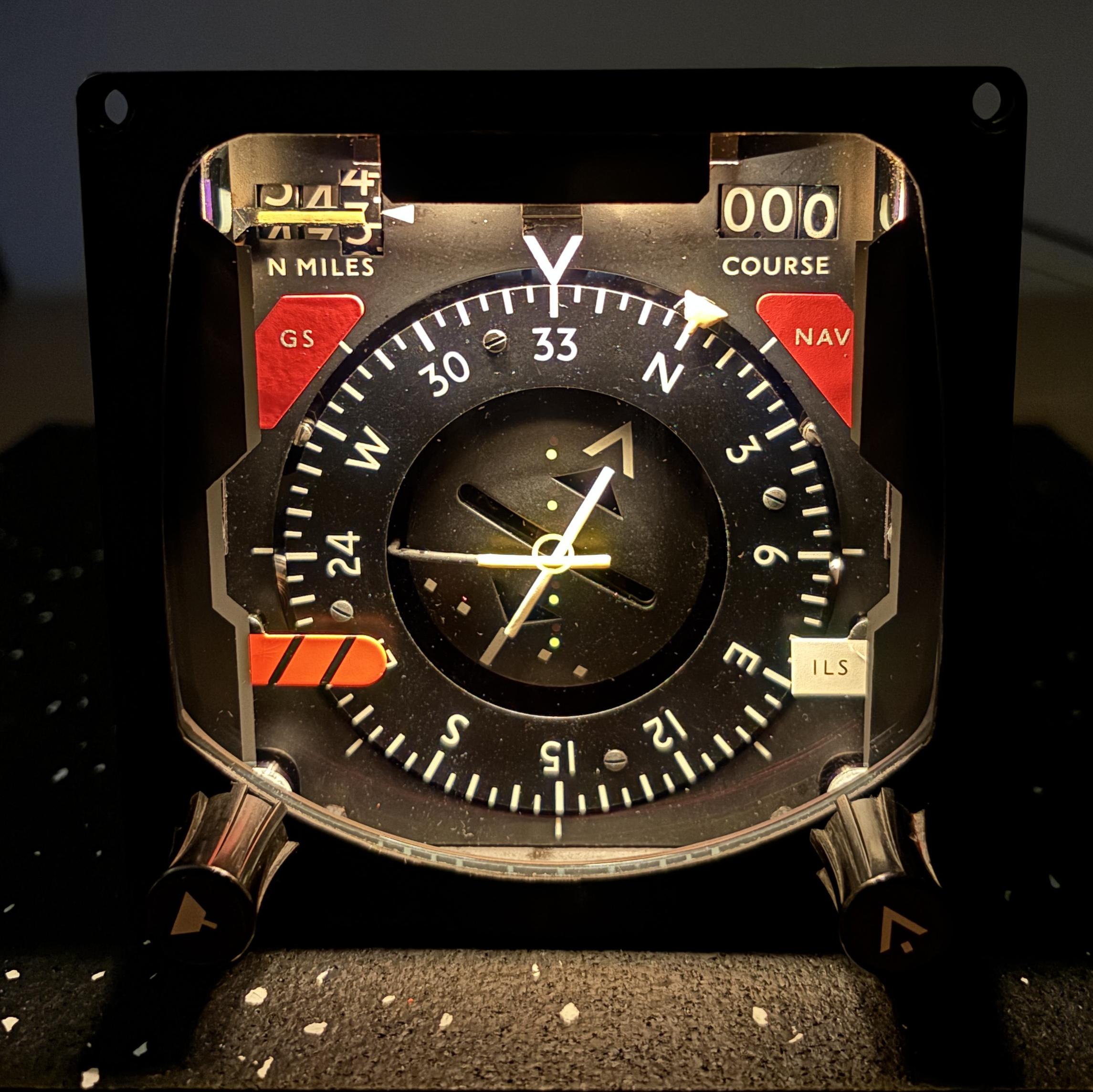
This Horizontal Situation Indicator (HSI) was manufactured by Smiths industries in the early 90s. It likely came from a decommissioned RAF aircraft such as the Panavia Tornado or Westland Sea King. The purpose of the HSI is to provide the pilot with several pieces of critical information in one module that is easy to read.
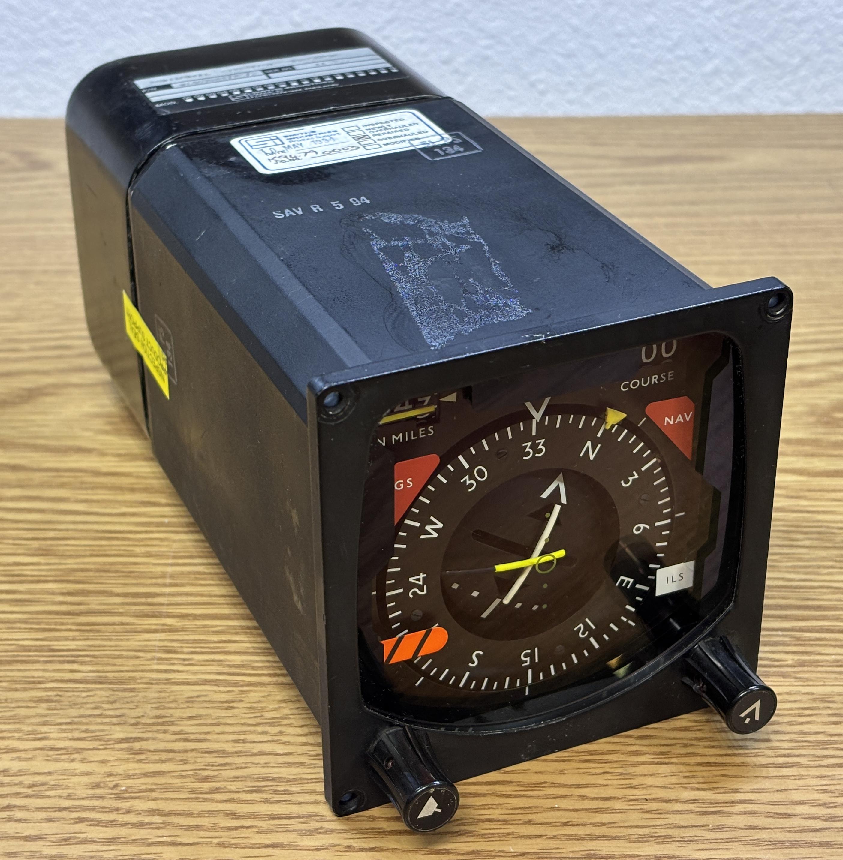
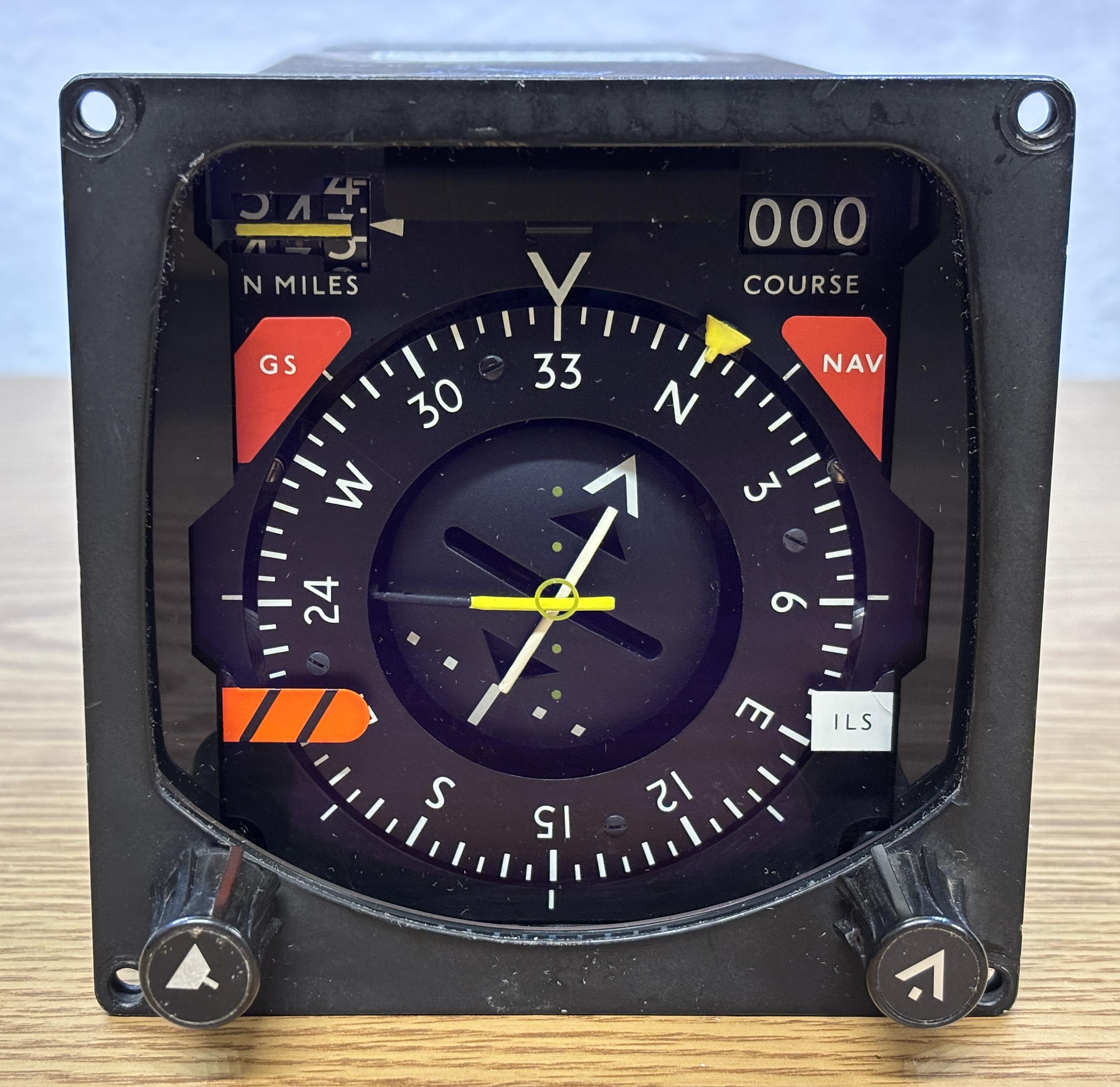
This HSI displays the heading, along with VOR-ILS information. The compass wheel indicates the current heading, and the small yellow trapezoidal symbol is the heading bug that is adjusted by the pilot to set the heading. The two lines in the center are used to display course deviations. There are four flags (one in each corner), the red (GS and NAV) and orange (heading) flags appear when an error is detected with the respective system which could mean the display is not accurate. The white ILS flag is likely just an indicator that ILS is in use. There are two digital indicators (mechanically actuated) that display the nautical miles (left) and course in degrees (right). There is also a small yellow flag that drops down in front of the nautical miles readout when there is a discrepancy. All flags are displayed when the HSI is not powered up or connected to a control system because the solenoids are spring loaded to display the flags by default (fail-safe condition). A thick piece of anti-reflective coated glass is installed in the front to protect the components behind it. The knob on the left adjusts the yellow heading bug and the knob on the right adjusts the course.
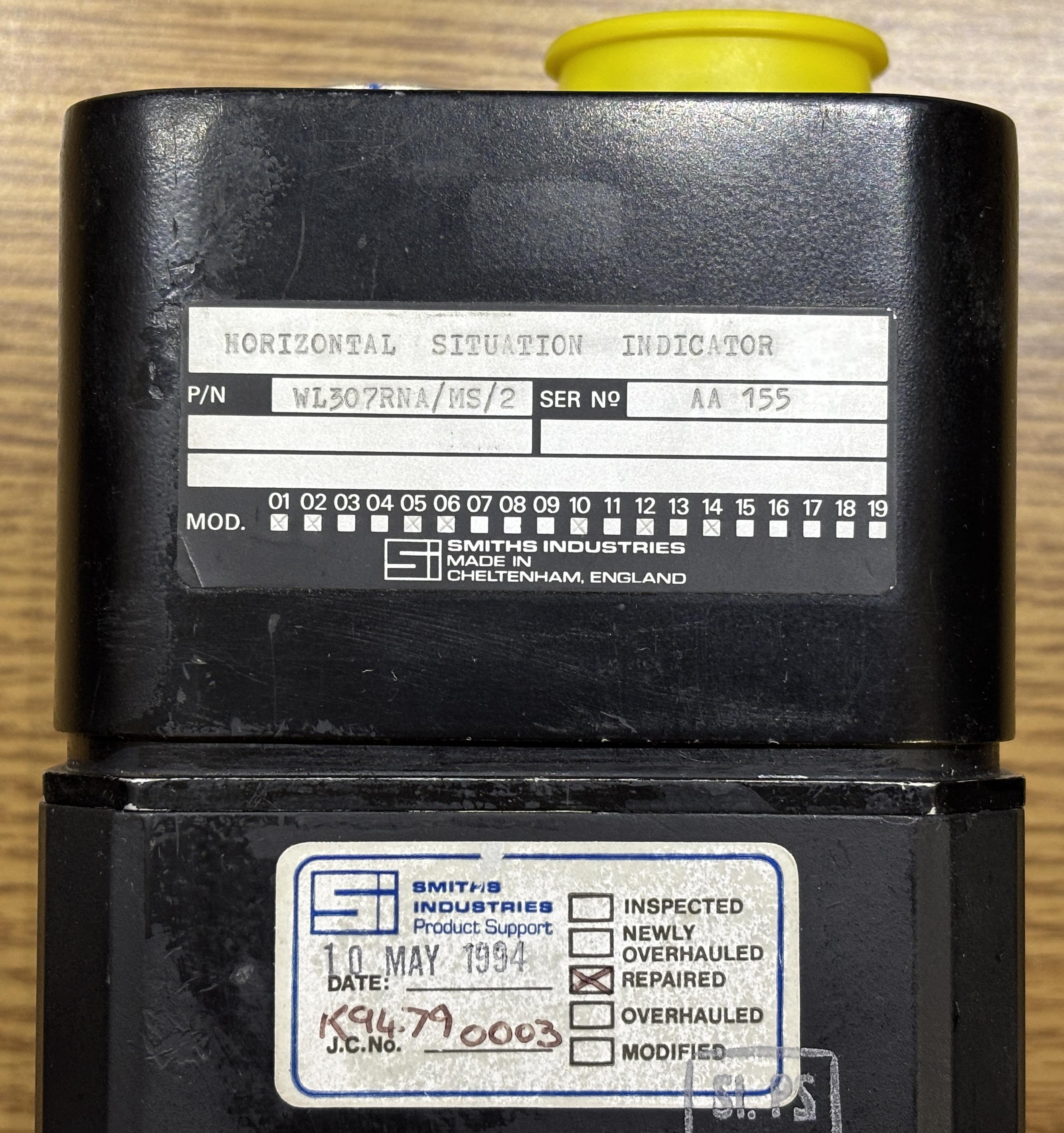
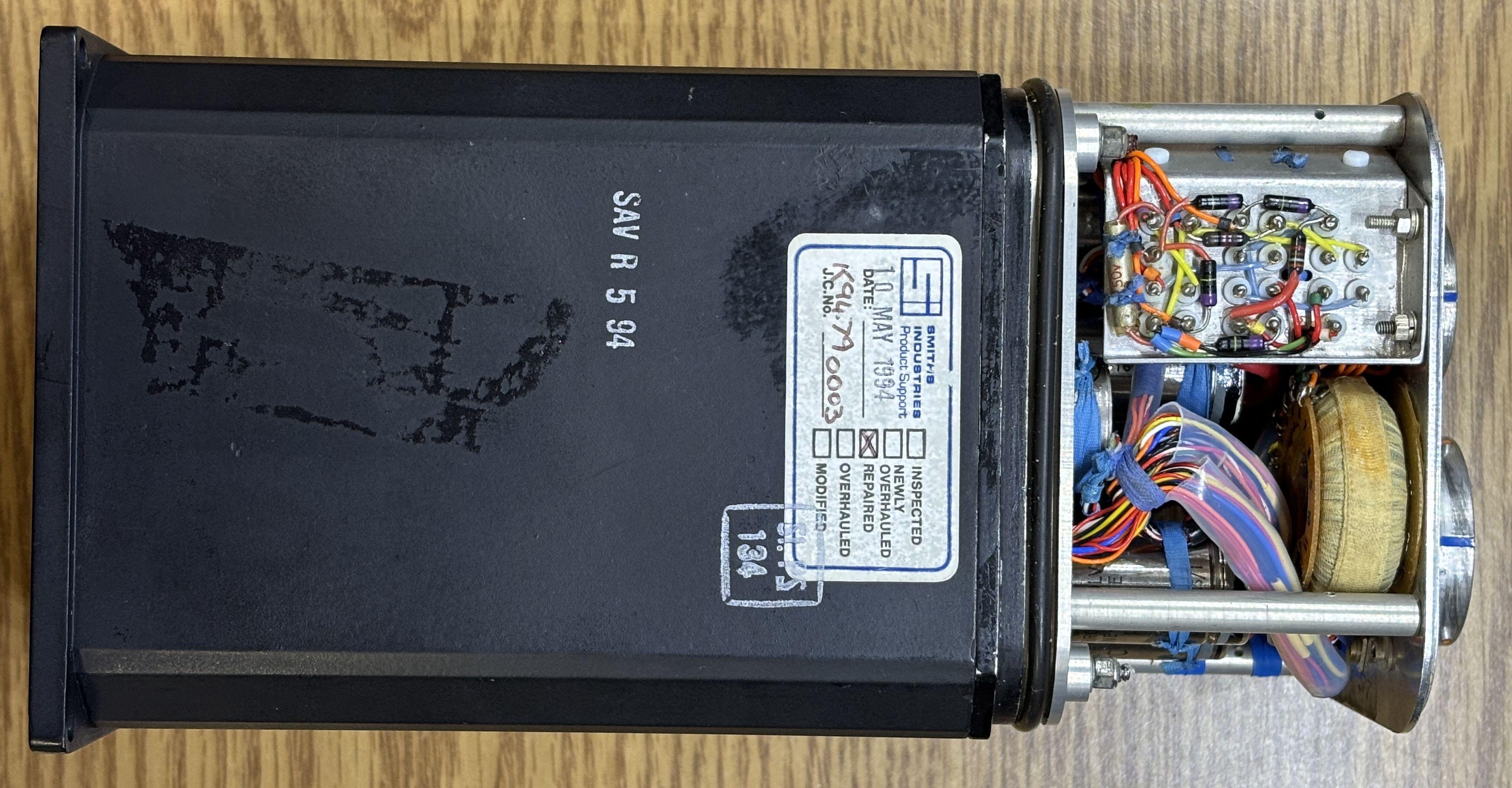
This HSI has a part number of WL307RNA/MS/2 and a pretty low serial number of AA 155. The square boxes on the bottom of the label indicate which modifications have been applied to the unit. Also, the sticker below indicates that this unit has been repaired by Smiths in 1994.
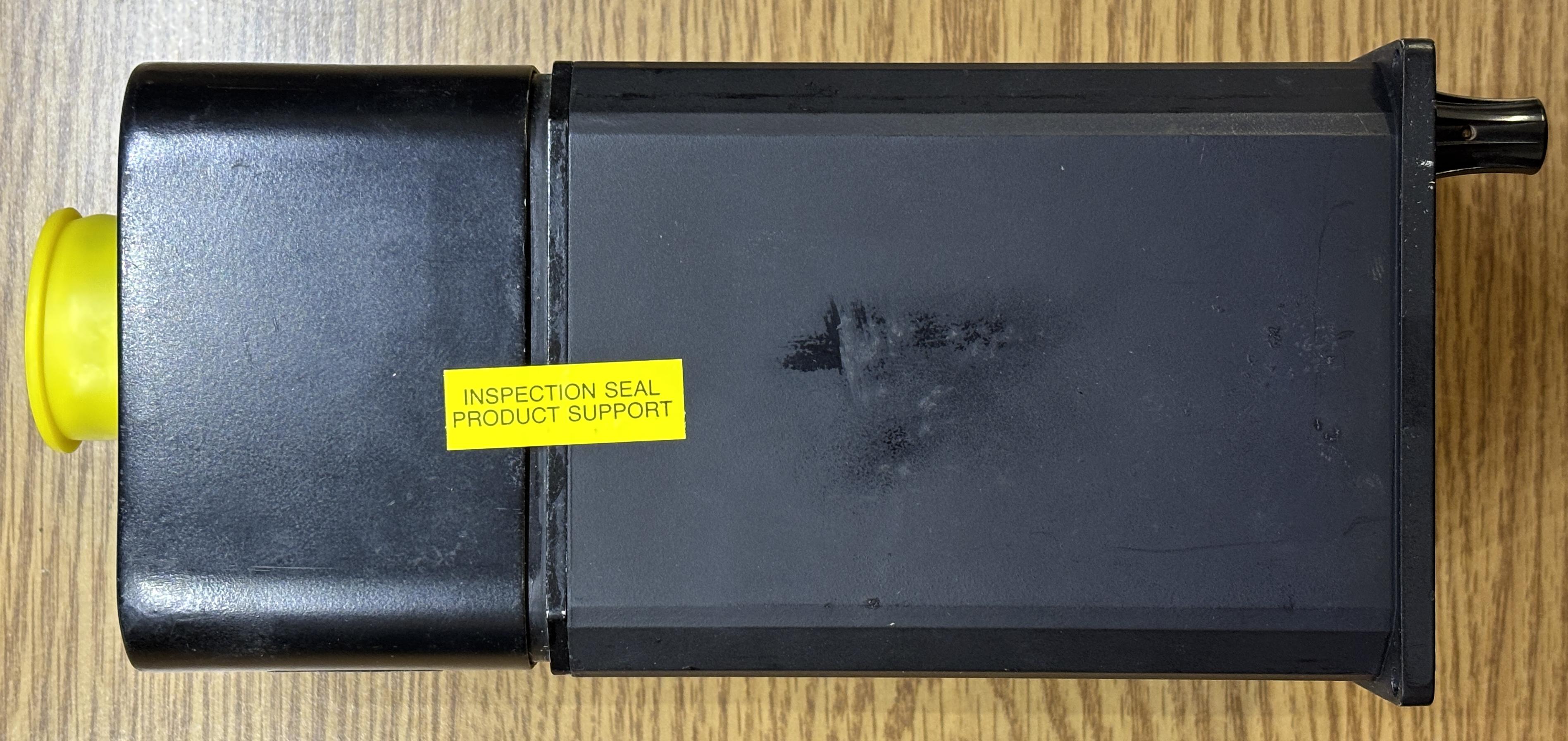
Here is a side view of the unit. The casing is all metal and separates in two sections once the fasteners are removed. The inspection sticker is where the two sides join.
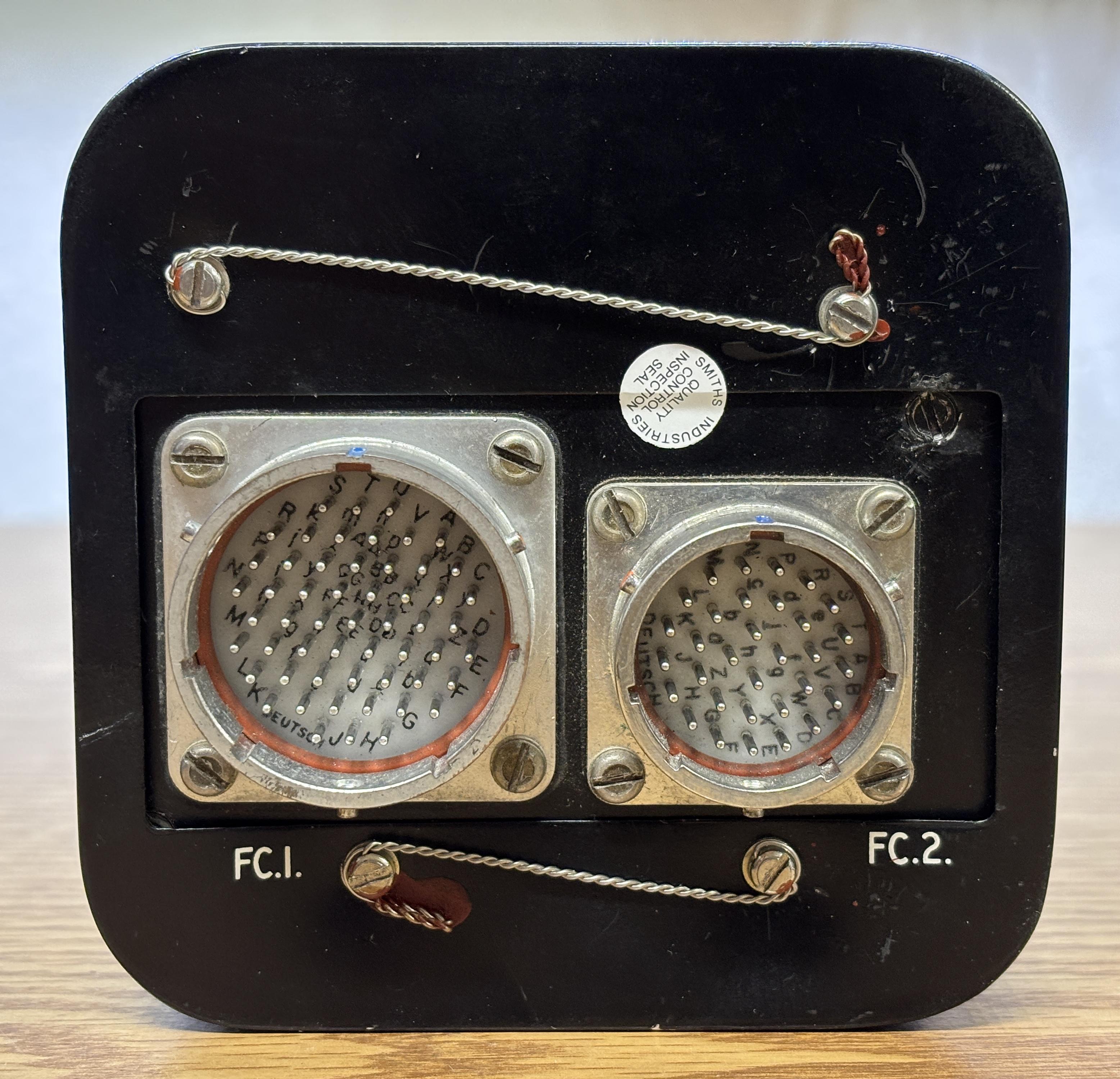
On the back of the unit are two Deutsch twist-lock connectors. One connector has 55 pins (FC.1) while the other has 32 pins (FC.2). There are four slotted screws that secure the back cover to the rest of the casing. Safety wire runs through holes in the screw heads to keep them from backing out during flight.
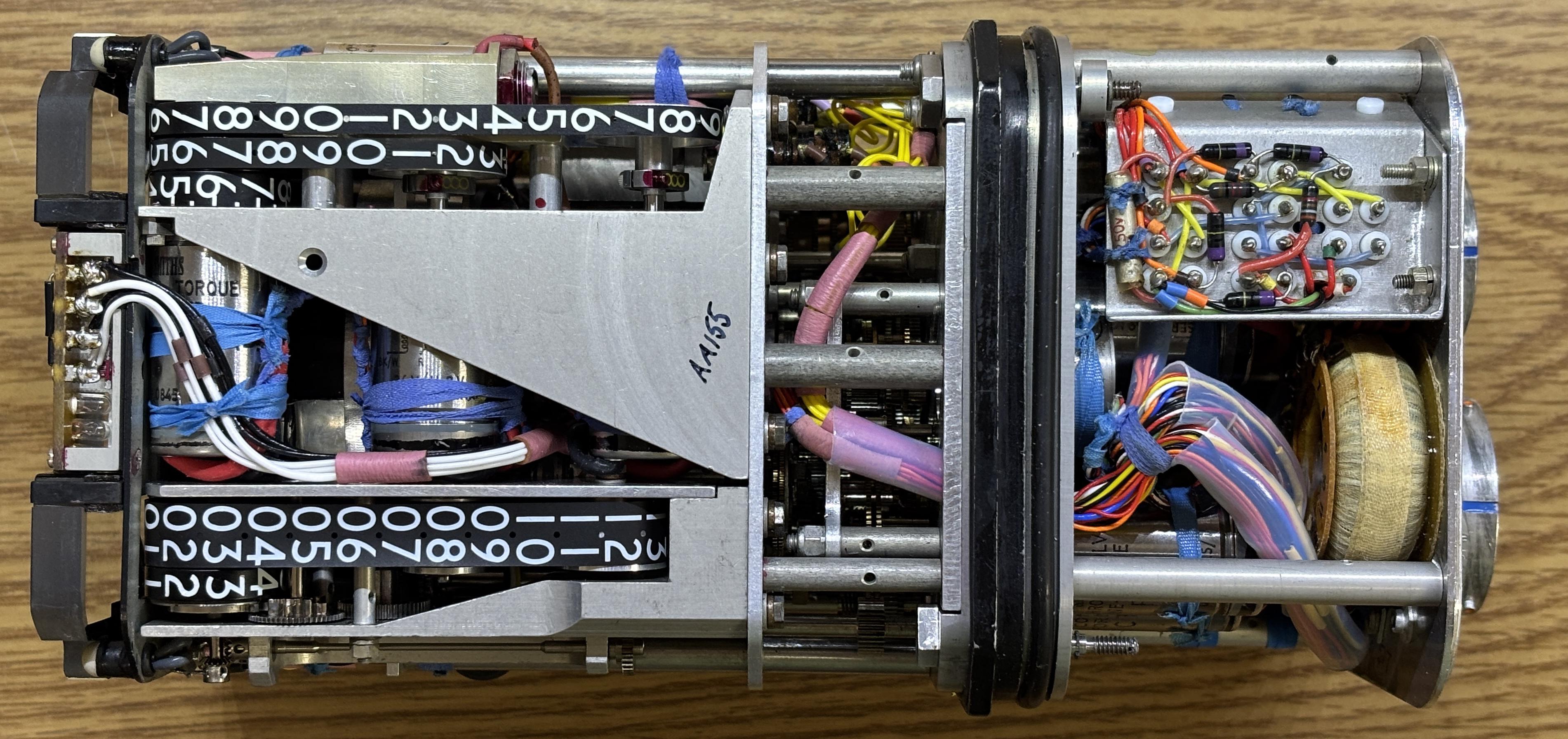
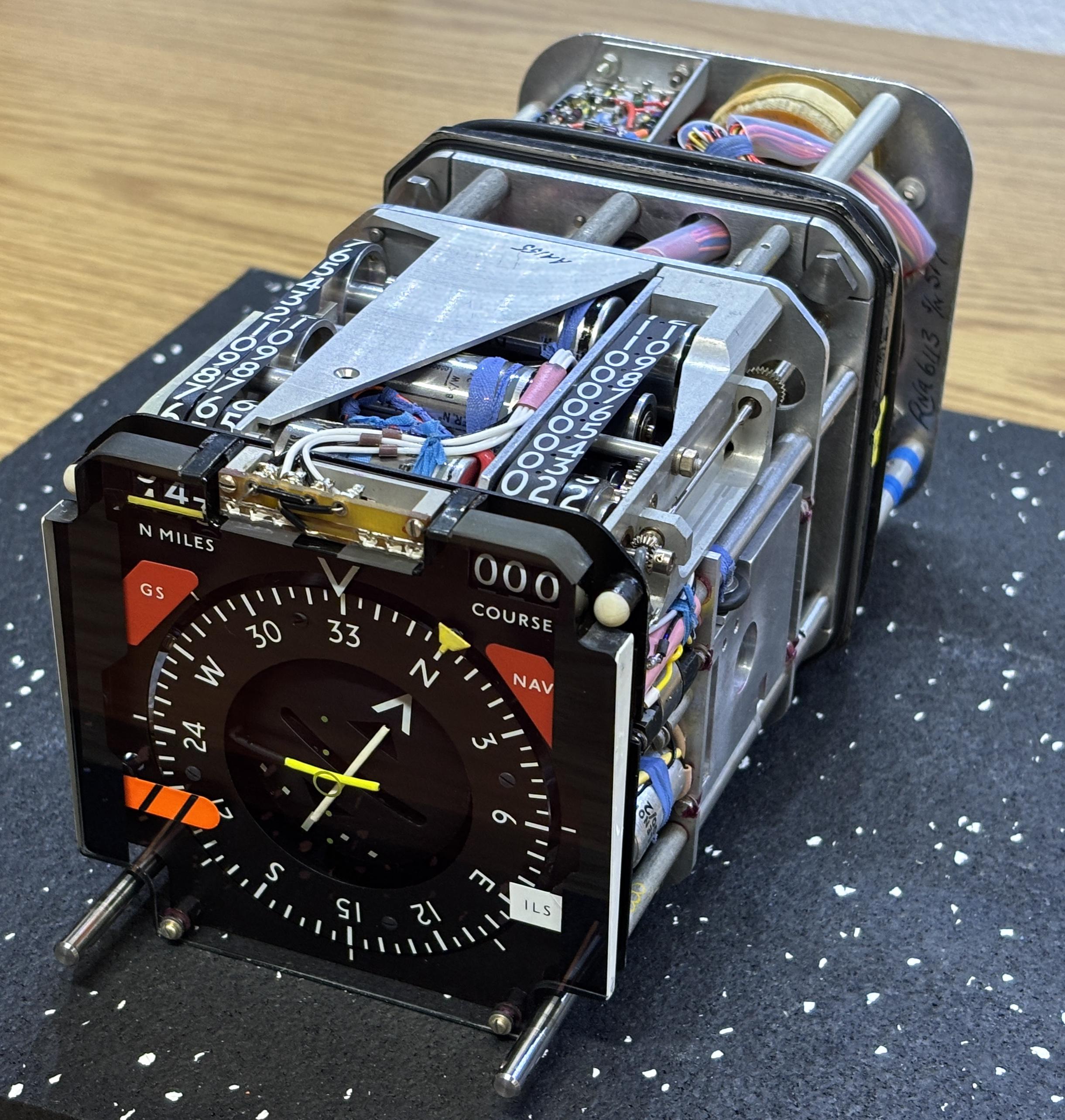
With the back cover removed, we get our first glimpse inside the unit. To remove the front section of the cover, you first have to remove the two plastic knobs. Then, four screws on the back side can be loosened to pull the front outer casing forward. These screws are captive and rotate a small metal plate about a quarter of a turn to release the front cover.
With both covers removed, we can see just how tightly packed and complicated this unit is. It's a wonderful example of classic electromechanical design. There do not seem to be any ICs or digital components inside (although some similar HSIs do have some digital circuitry). Many of the components visible in the front such as the compass card, course indicator, and distance readout are controlled by complex gear arrangements driven by synchro motors. Synchro resolvers are used to detect the position of different components such as the aforementioned as well as the heading bug and pilot-configured course. Synchro transformers are used to compare two angular outputs and output a signal that is proportional to their difference. This HSI contains several of each of these along with solenoids to actuate the flags and galvos to control the course deviation indicators. There are several incandescent bulbs on the front to illuminate the HSI at night. There is a small transformer mounted to the back.
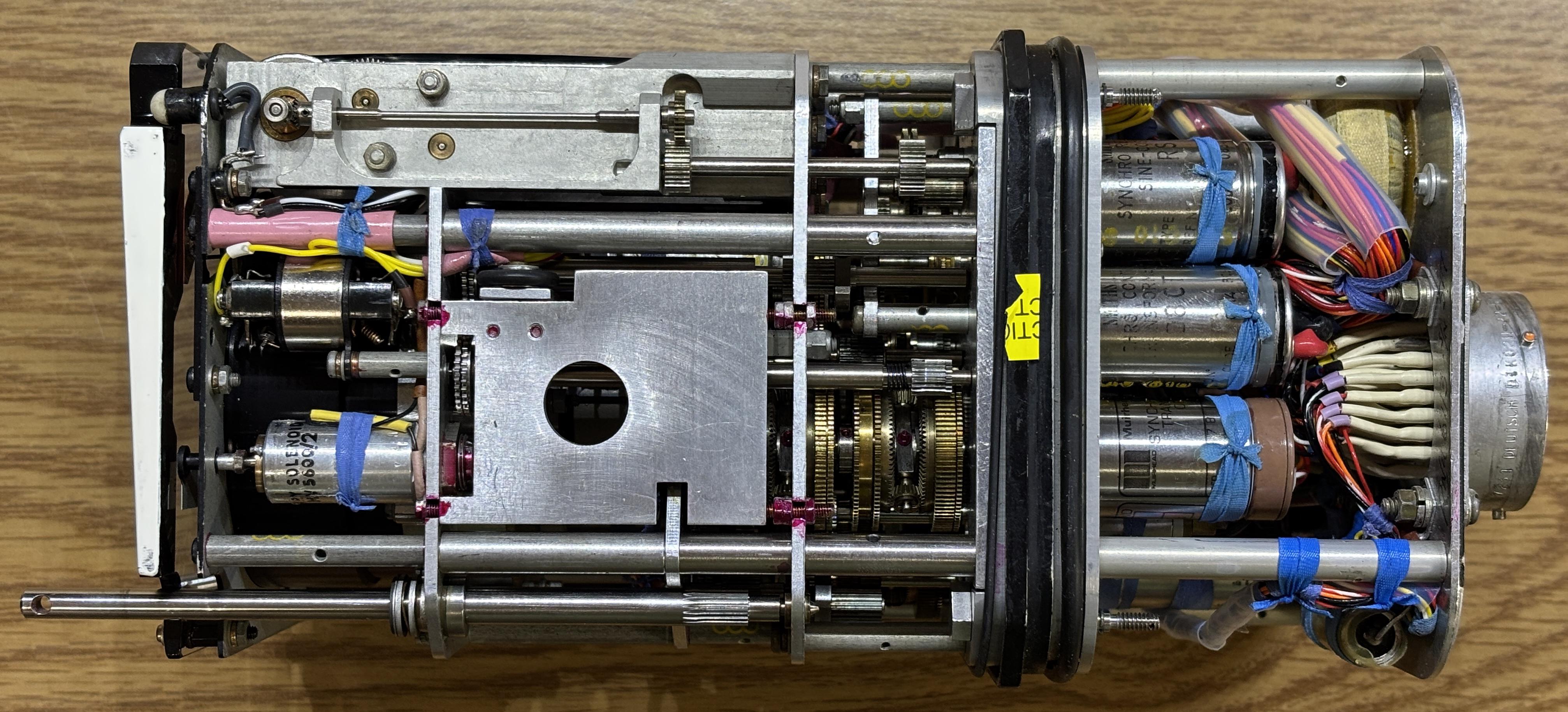
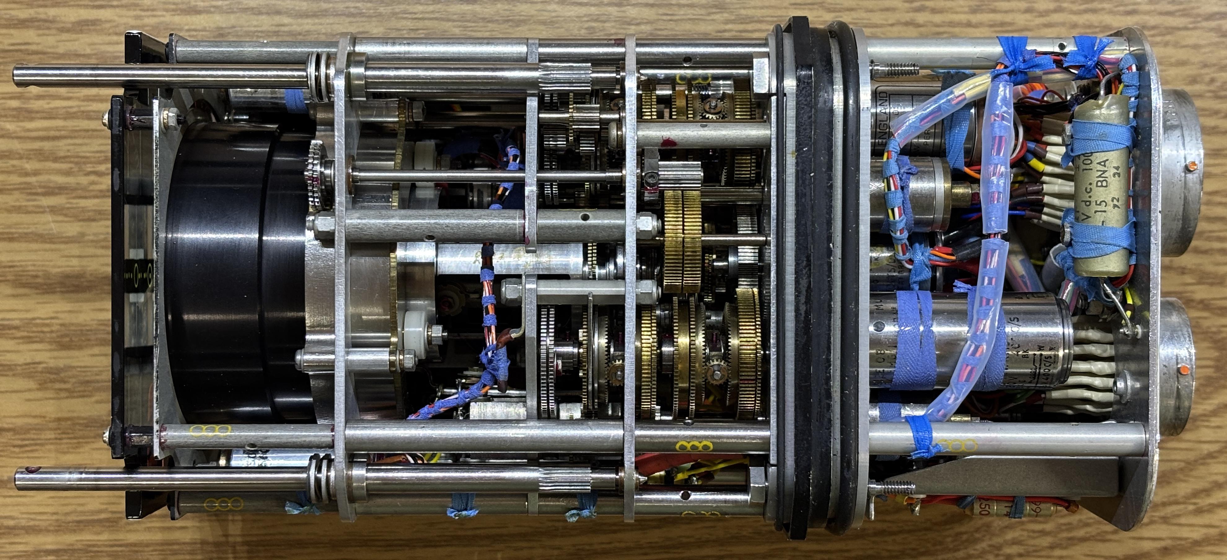
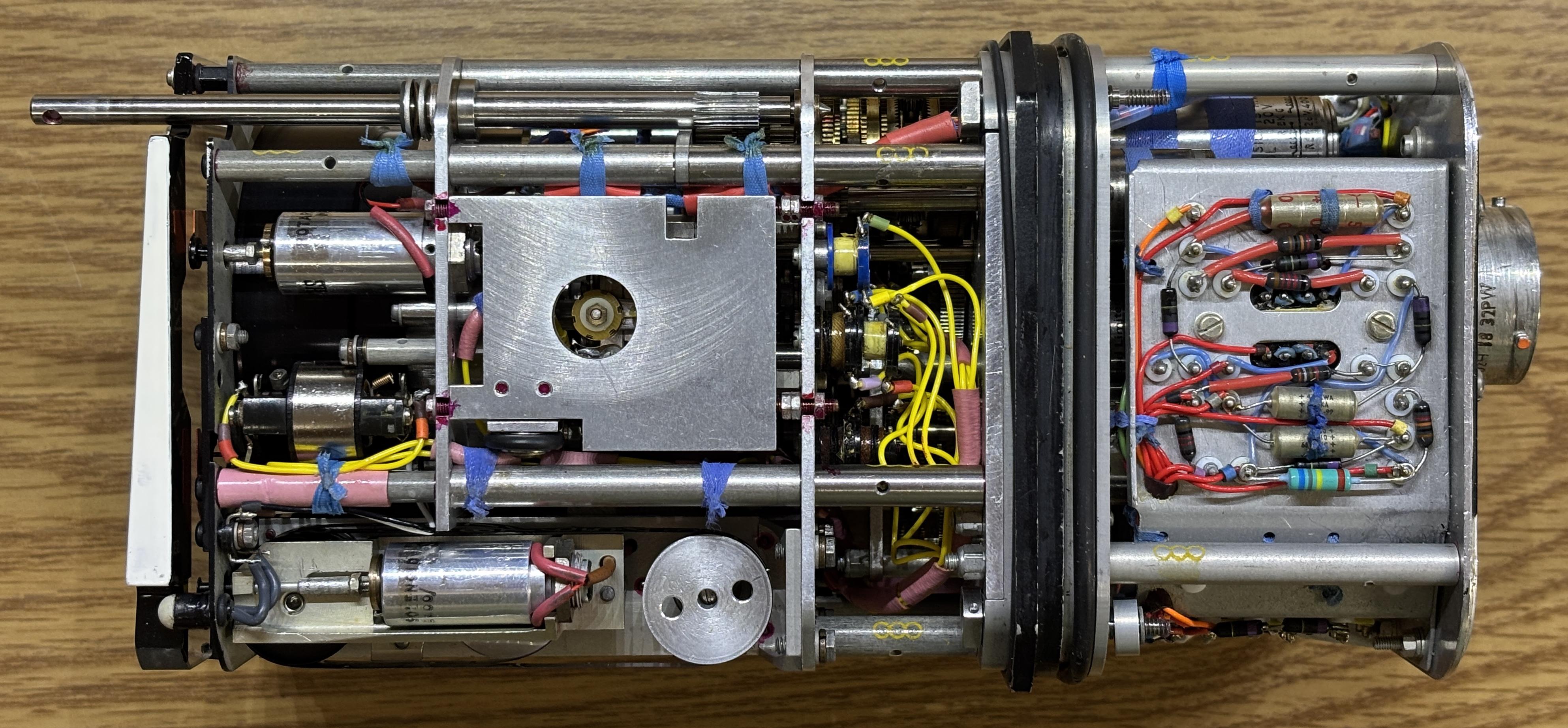
The digital readouts are fascinating as they use a purely mechanical design. They are continuous bands of a thin plastic material with numbers printed on them. These bands are actuated by various synchro motors to adjust the values displayed on the front.
Applying 5V DC to pins DD (+) and EE (-) of the FC.1 connector will illuminate the incandescent backlight. Our goal is to get this HSI controllable by a flight simulator, but that's going to be an involved project.
Visit the links below for some videos regarding a very similar HSI and a GitHub repo with some useful information for controlling the HSI with an Arduino.