DISCLAIMER: This control panel is a demilitarized surplus component purchased through civilian channels. It contains no cryptographic hardware, classified technology, or active radio capability. It is presented here solely for historical and educational interest. Nothing in this article should be interpreted as technical guidance for operating, replicating, or transmitting on military communications systems.
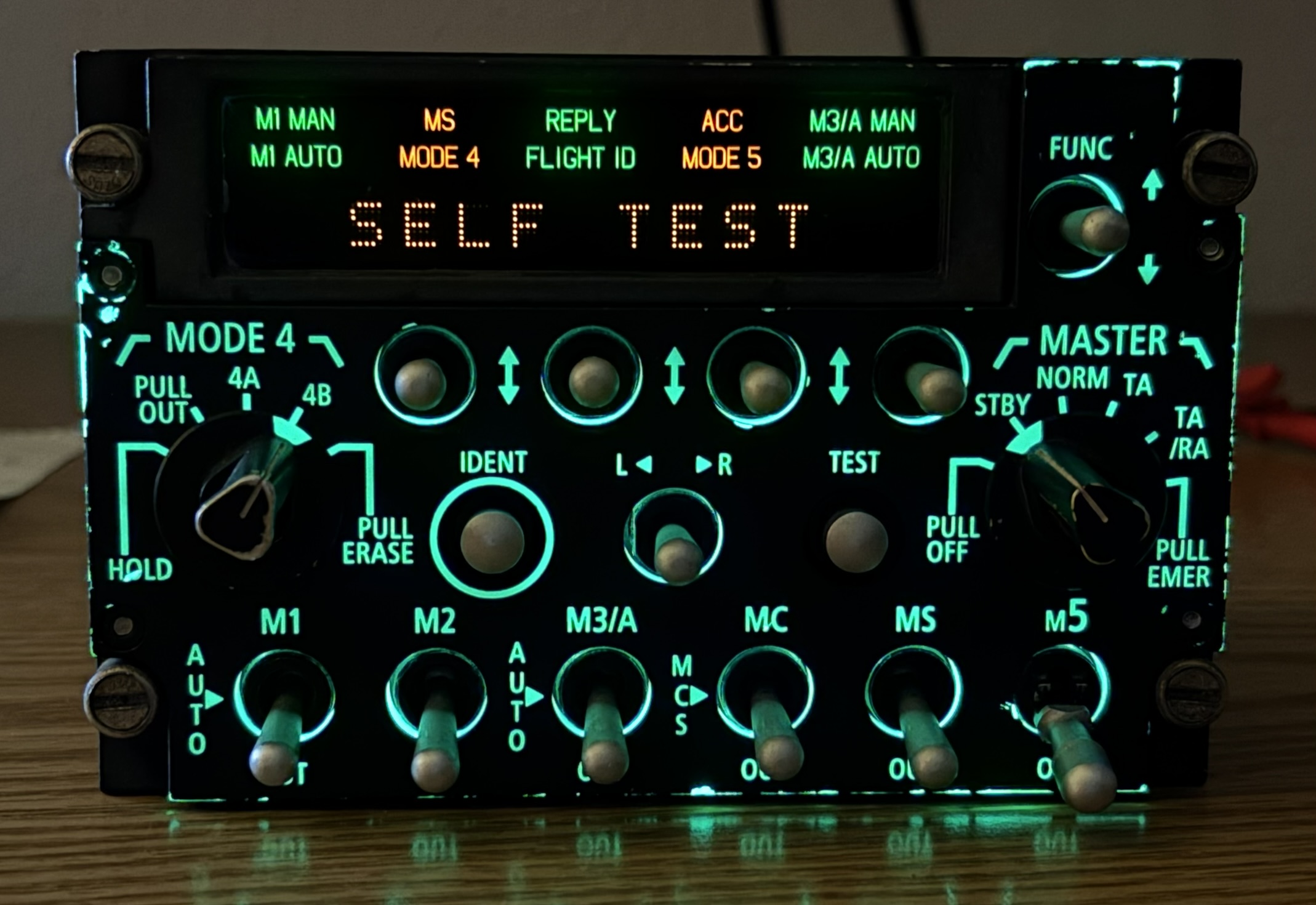
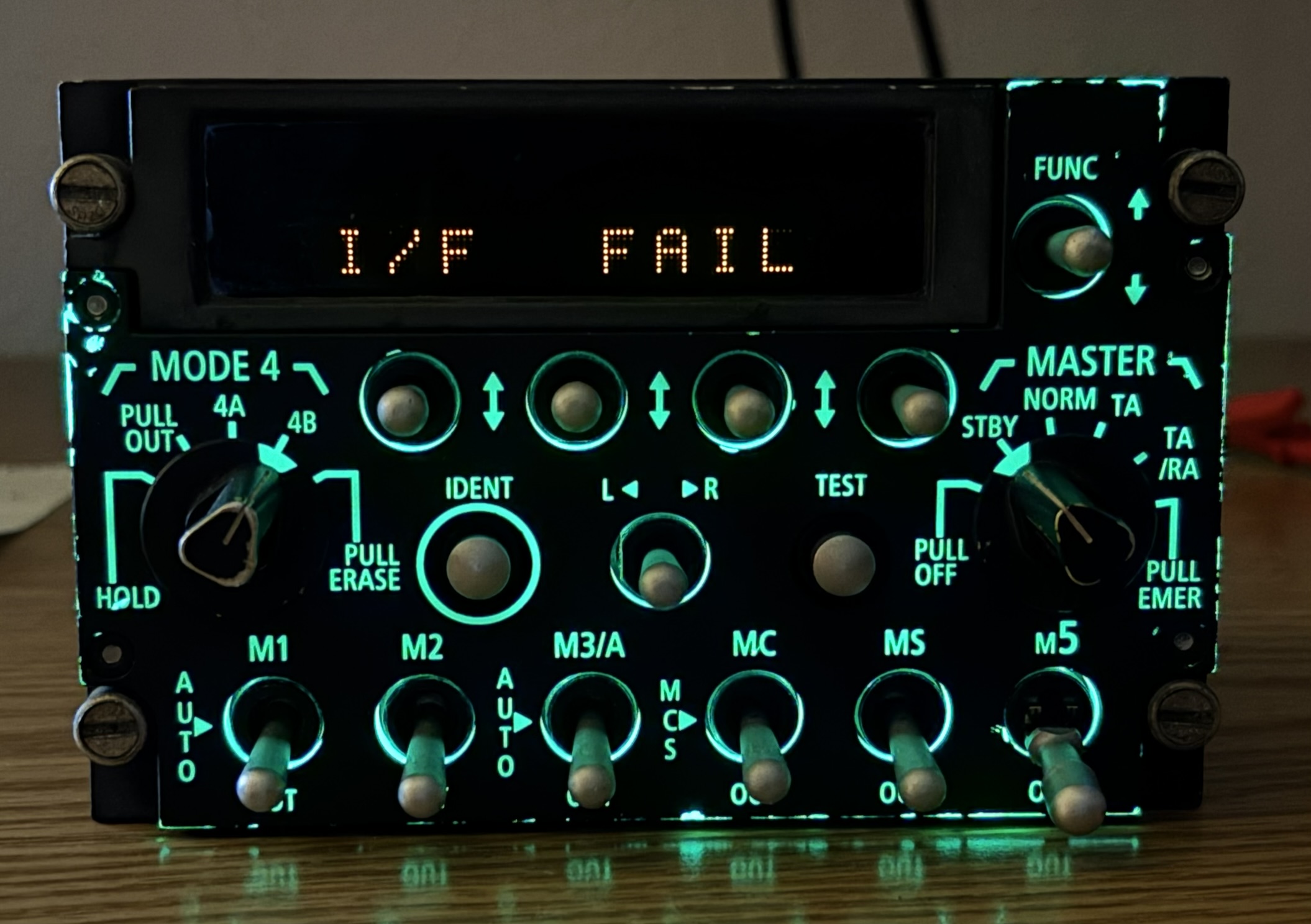
The Raytheon SIFF 4870 transponder CDU is the pilot's interface for the transponder system equipped in various (NATO) military aircraft. We found a picture of a Westland Sea King cockpit that had the CDU installed, however this unit could have probably been found in other aircraft as well. The CDU is a small metal box that mounts to the rack system in the cockpit using quarter-turn retention screws in each corner, common in many aircraft. On the CDU are several high-quality metal toggle switches, a couple of momentary buttons, two rotary selector switches, and a single-color LED-matrix screen with some additional indicators above. The panel is backlit so the controls and markings are clearly visible in a dark cockpit. The CDU is used to control and monitor the transponder system located elsewhere in the aircraft.
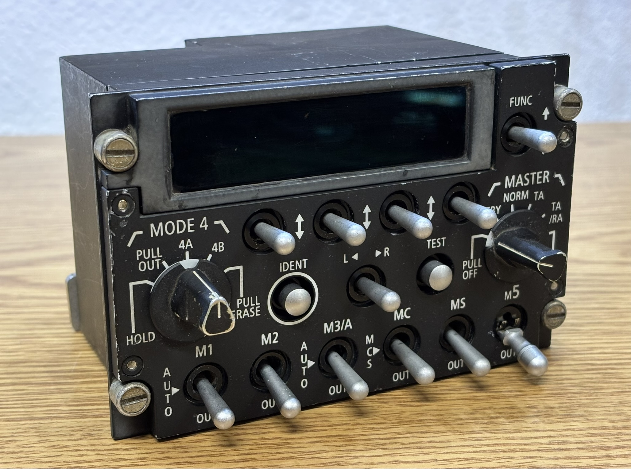
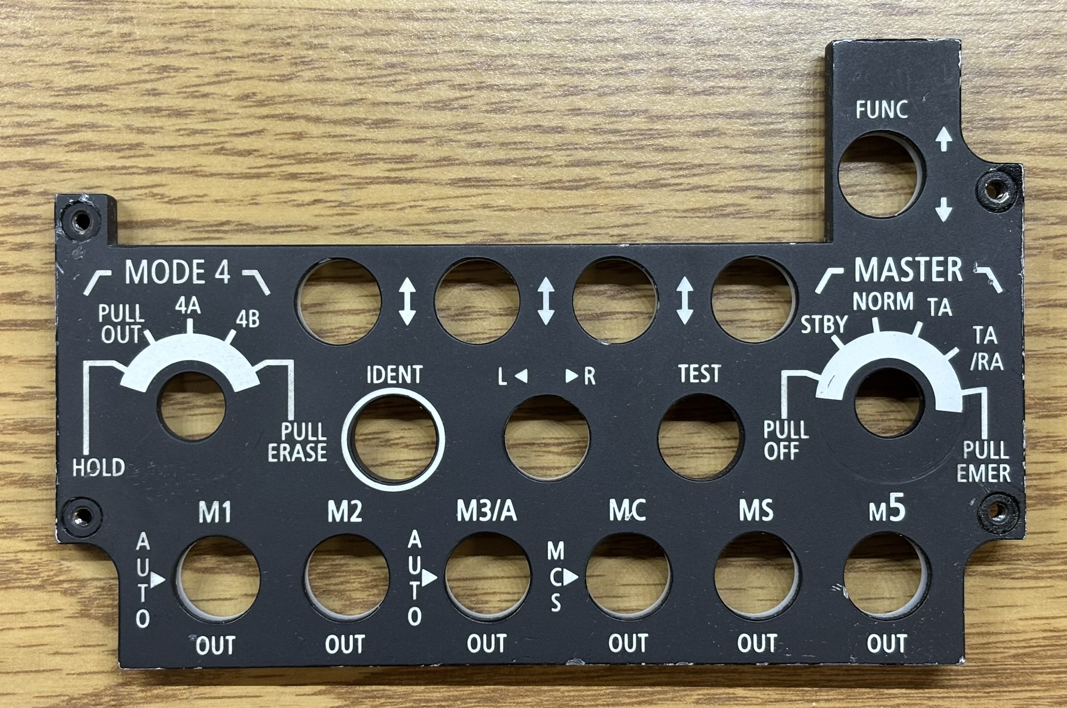
Below is a list of each switch on the control panel along with its function.
MASTER rotary switch
- PULL OFF: Isolates power from the system (totally off)
- STBY: Standby mode, system is powered on but not able to transmit or receive
- NORM: Normal operating mode
- TA: Traffic advisory only
- TA/RA: Traffic advisory and resolution advisory
- PULL EMER: Emergency mode, may transmit emergency squawk code
MODE 4 rotary switch
- HOLD: momentary position - function unknown
- PULL OUT: Disables mode 4 transponder operation
- 4A: Provides a 3-pulse reply with a delay based on an encrypted challenge (key set "A")
- 4B: Provides a 3-pulse reply with a delay based on an encrypted challenge (key set "B")
- PULL ERASE: Immediately zeroizes (destroys) all crypto keys stored on the transponder
FUNC toggle and 4 toggle switches below display: soft keys to flip through menu items and adjust parameters shown on the display (such as squawk code)
IDENT button: Transmits a mode 3/A identification ping that is visible to ATC
L/R toggle: Switches between left and right displayed frequencies or identifiers
TEST button: Manually initiates built in self-test function
MODE selection toggle switches: These switches are used to enable and disable specific transponder/interrogation modes. Some are just on or out (off), while others are 3 position toggles that also have an "auto" function that allows the mission computer to determine whether that mode is active based on mission parameters. The OUT terminology is most likely used to avoid confusion between the master switch's OFF position which turns the entire transponder off. "OUT" just pulls the specified transponder mode out of operation. There are many more transponder modes available to the military in addition to the standard civil/commercial aviation modes. This control panel allows essentially any combination of the modes to be enabled as needed.
- M1: (ON/AUTO/OUT) provides a 2-digit 5-bit mission code that can be selected by the pilot [military only]
- M2: (ON/OUT) provides a 4-digit unit code [military only]
- M3/A: (ON/AUTO/OUT) provides a 4-digit identification (squawk) code that can be changed by the pilot [military & civilian]
- MC: (ON/MCS/OUT) extension of mode 3 that provides the aircraft's altitude [military & civilian]
- MS: (ON/OUT) supports multiple formats, aircraft is assigned a fixed 24-bit address [military & civilian]
- M5: (ON/OUT) cryptographically secured version of mode S that also includes the ADS-B GPS position [military only]
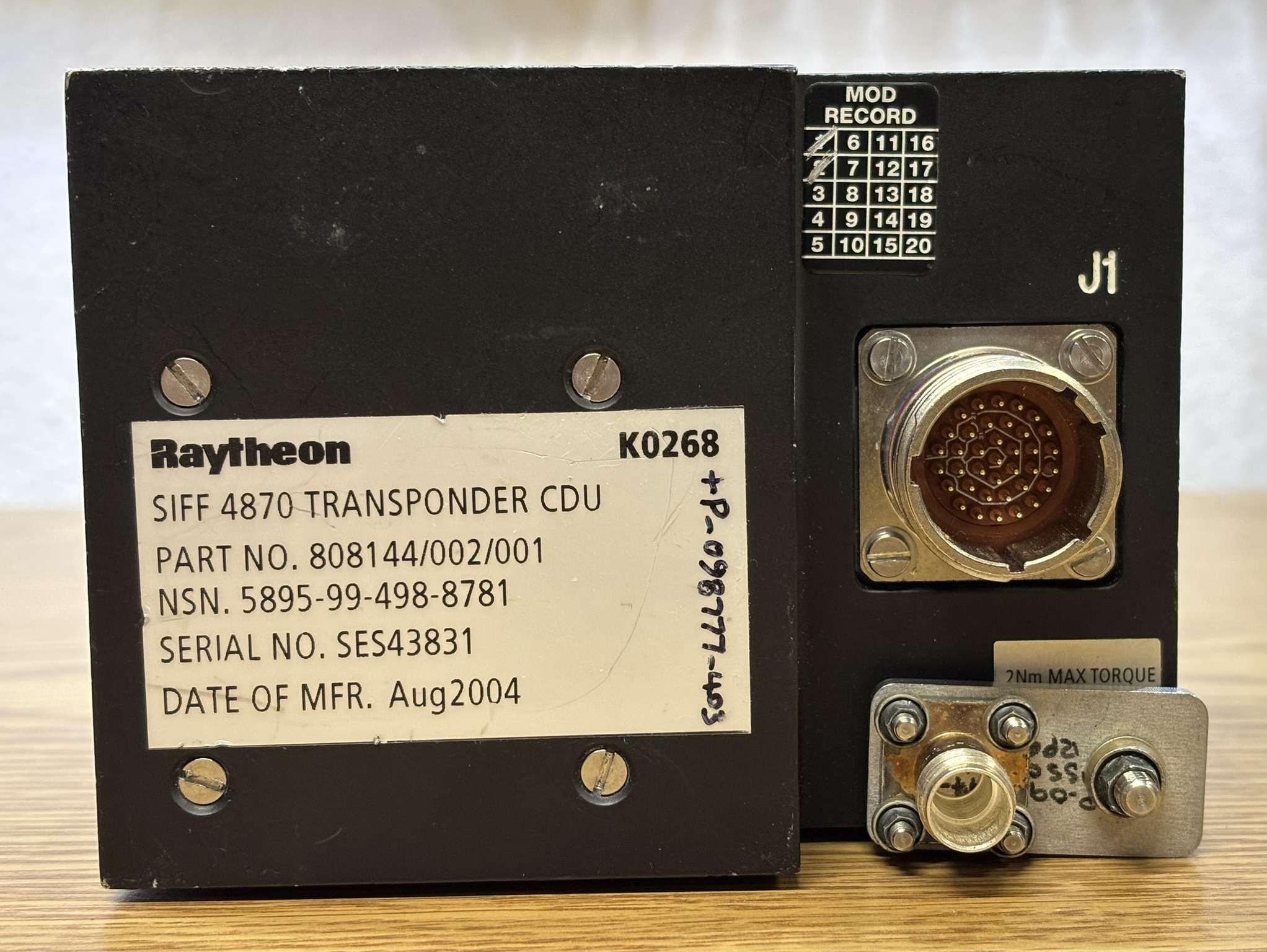
On the back of the unit is an identification sticker that indicates the unit was manufactured in August of 2004. There is also a modification record label with a few boxes containing a strike, indicating a couple modifications have been applied to this unit. Next is the J1 connector, which is a 37-pin Deutsch DTS20F15-35PN mil-spec (MIL-DTL-38999) twist-lock connector. Below that is a grounding stud to which a piece of metal and a blank screw connector is mounted to. A pin-out for the 37-pin connector will be provided towards the bottom of this page.
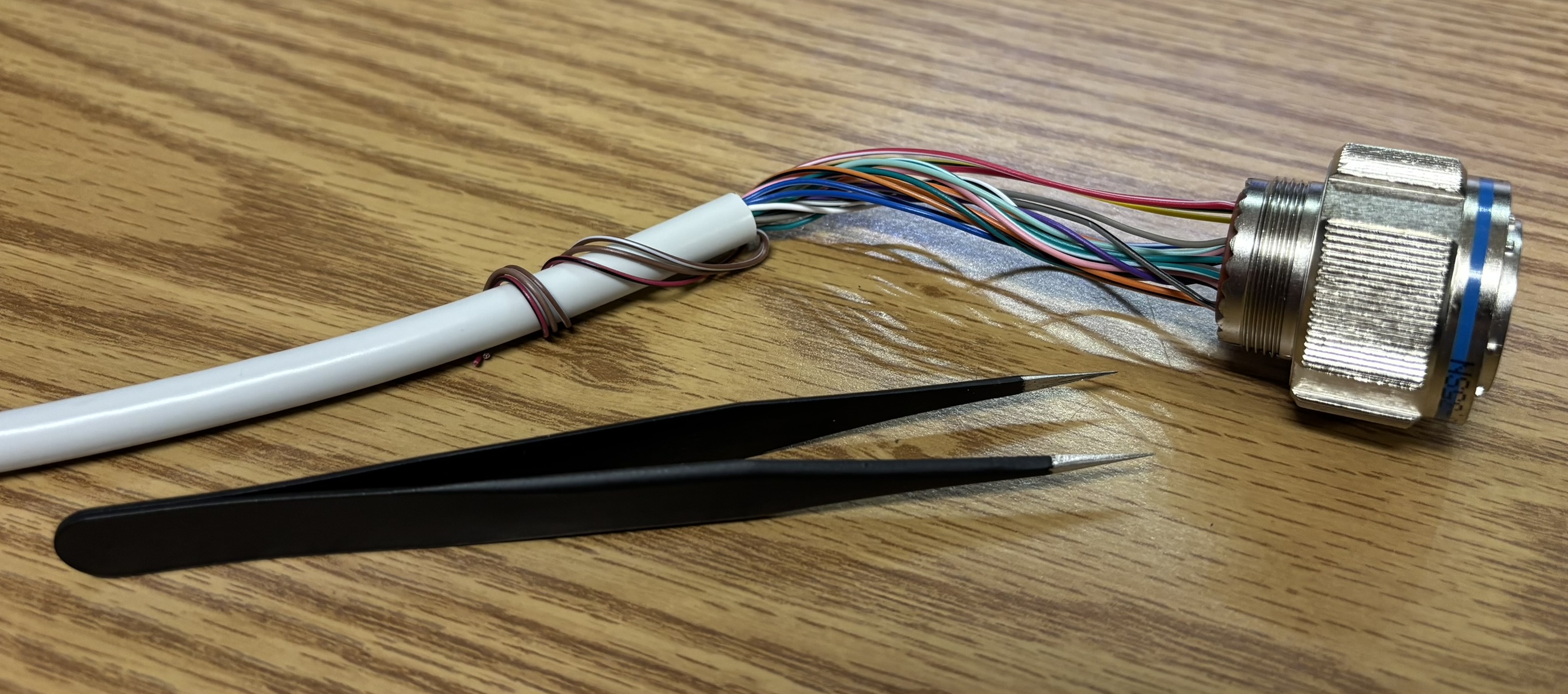
We found and purchased the mating Deutsch connector (DTS26F15-35SN) for the CDU and made a custom wire harness with an old parallel cable. This allowed us to easily power the unit and access the RS-485 interface. It's worth noting that a tweezers with a sharp point works great as an insertion tool for getting the pins into the connector.
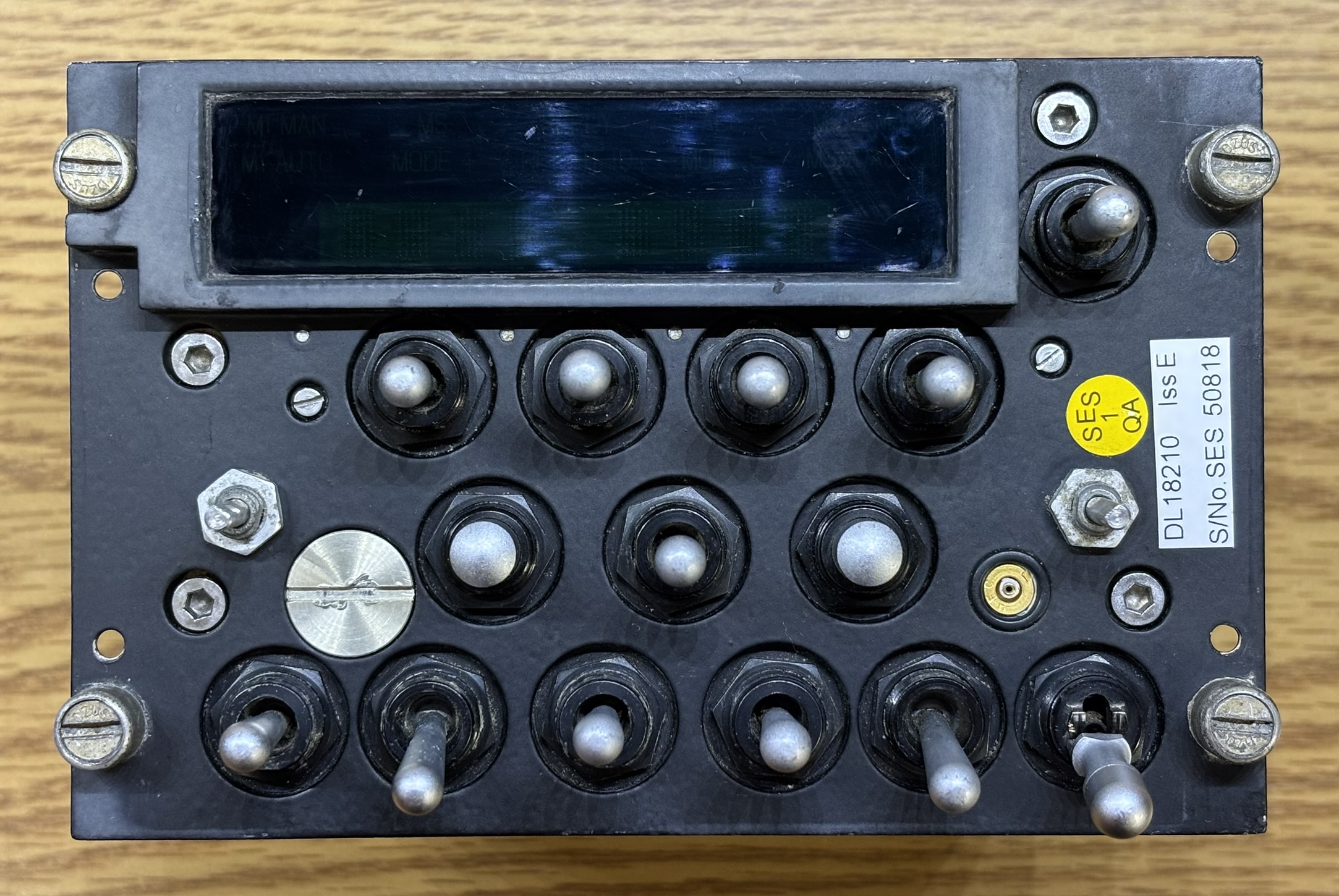
This is a top view of the CDU. The red plastic cap was originally installed over the twist-lock connector to keep out dust and debris.
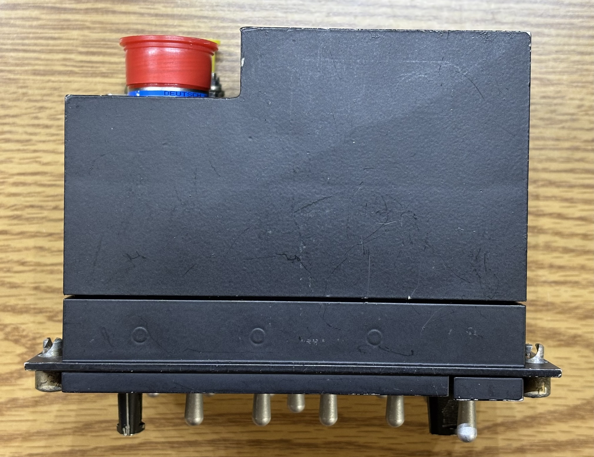
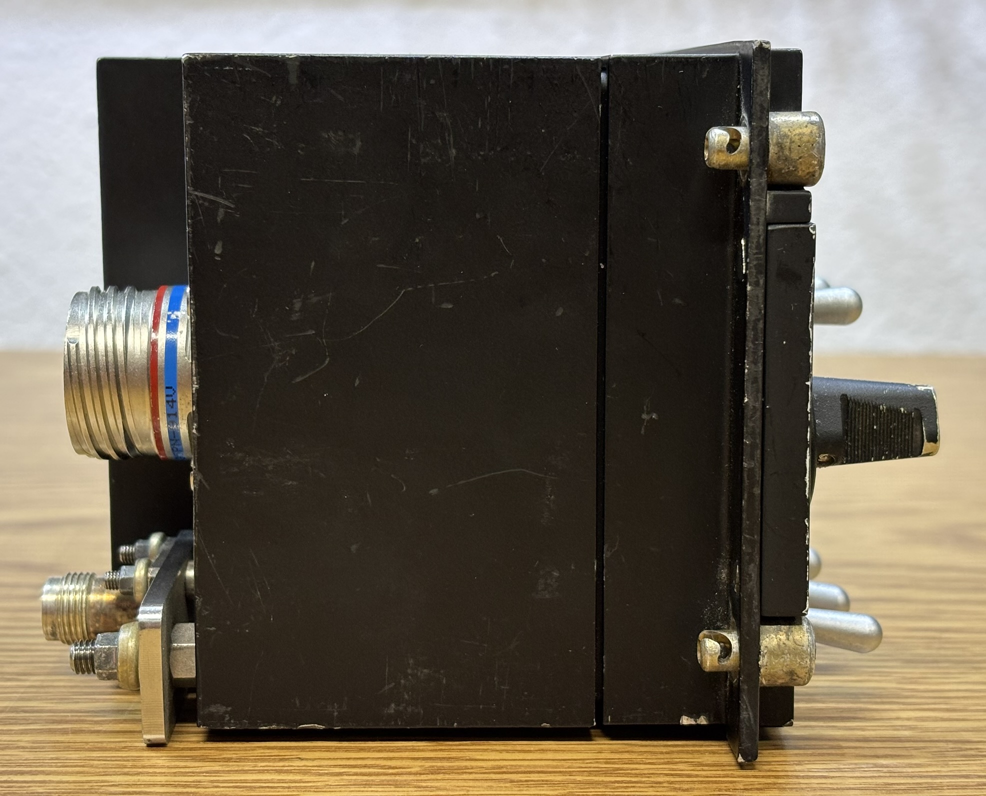
This side view clearly shows how the quarter-turn screws in the corners are used to secure the panel into the rack/frame in the cockpit.
Removing both rotary selector knobs and four rear-mounted slotted screws allows the backlight panel to be pulled away from the metal casing. Each toggle switch and button is secured to the front metal frame by a locking nut. The rotary selector switches are installed in the same manner and use "D" shaped shafts. The gold-colored plug is for the backlight connection and uses a center pin and concentric ring socket to mate with a connector on the backlight panel.
This is the backlit front panel. It's a translucent piece of plastic cut and drilled to mount around the switches and controls. It is then covered with a black opaque coating and potentially a white layer in between. From there, the panel is etched to form the text and lighted sections around the switches. Light produced by small bulbs contained within the panel that illuminate the etched text and sections to create a clearly legible panel during both day and night.
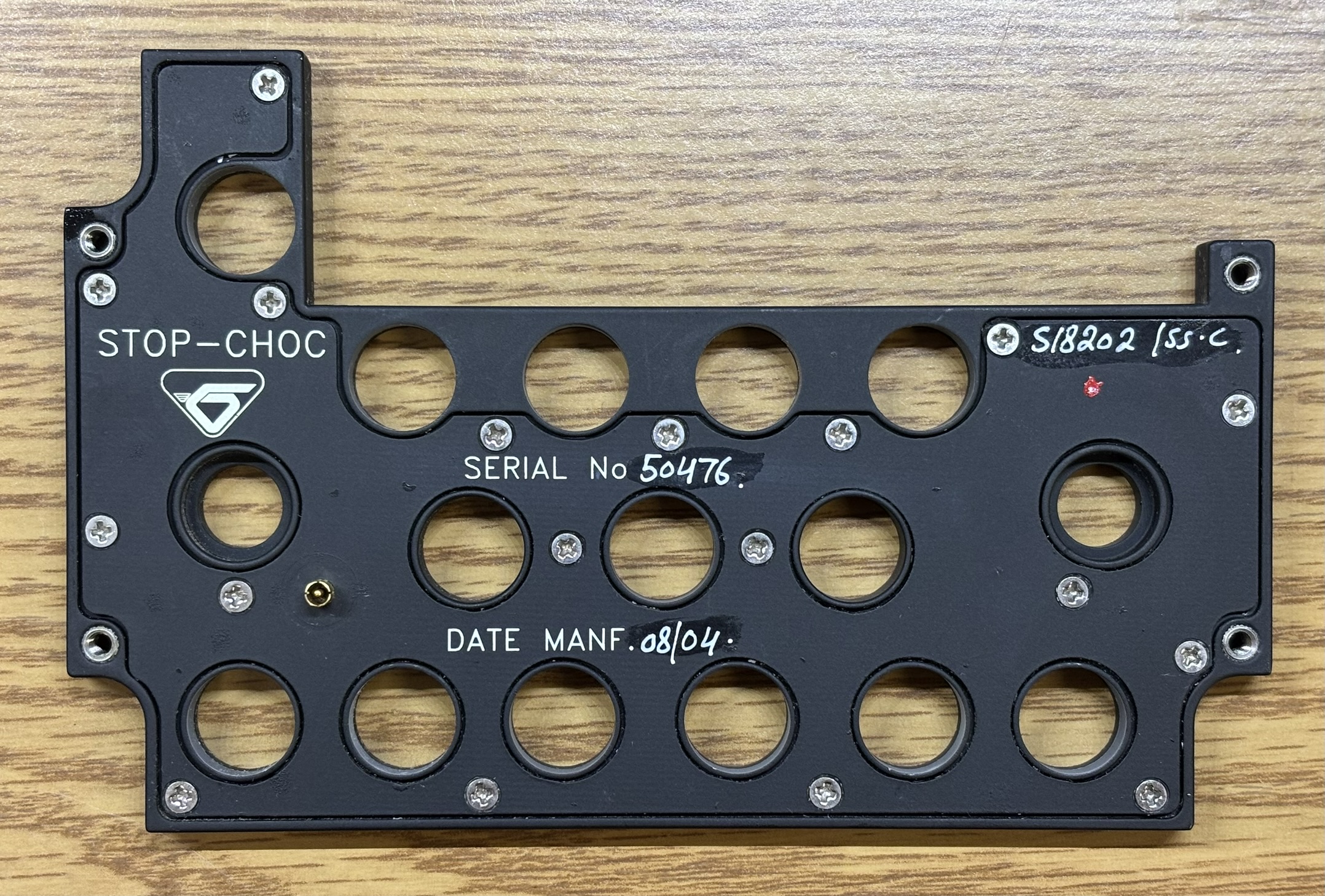
On the back of the illuminated panel are several screws that join a thin PCB with the light bulbs and connections to the front plastic section. The assembly was manufactured by Hutchinson STOP-CHOC of Germany.
We originally did not want to disassemble the backlight panel due to its delicate nature, but had no choice when the backlight suddenly stopped working. Luckily, it was not as bad as we thought. In the image below you can see the thin PCB with the bulbs and traces that form a series/parallel arrangement.
Each tiny incandescent bulb is covered by a translucent plastic cylinder to spread and diffuse the light. It also determines the color, which is green in this case. The bulbs are surface-mount soldered to the thin PCB.
The issue with the backlight panel turned out to be a problematic solder joint at the electrical connector. We had to chip away some plastic from the connector, de-solder and remove, and then re-install the connector. We actually installed the PCB and connector in its socket to ensure the pin was correctly centered in the ring. The repair worked and the backlight is now fully functional! We also noticed that there was a slight internal short somewhere in the PCB, but it is easily overcome by the 24-28V DC power and is not an issue.
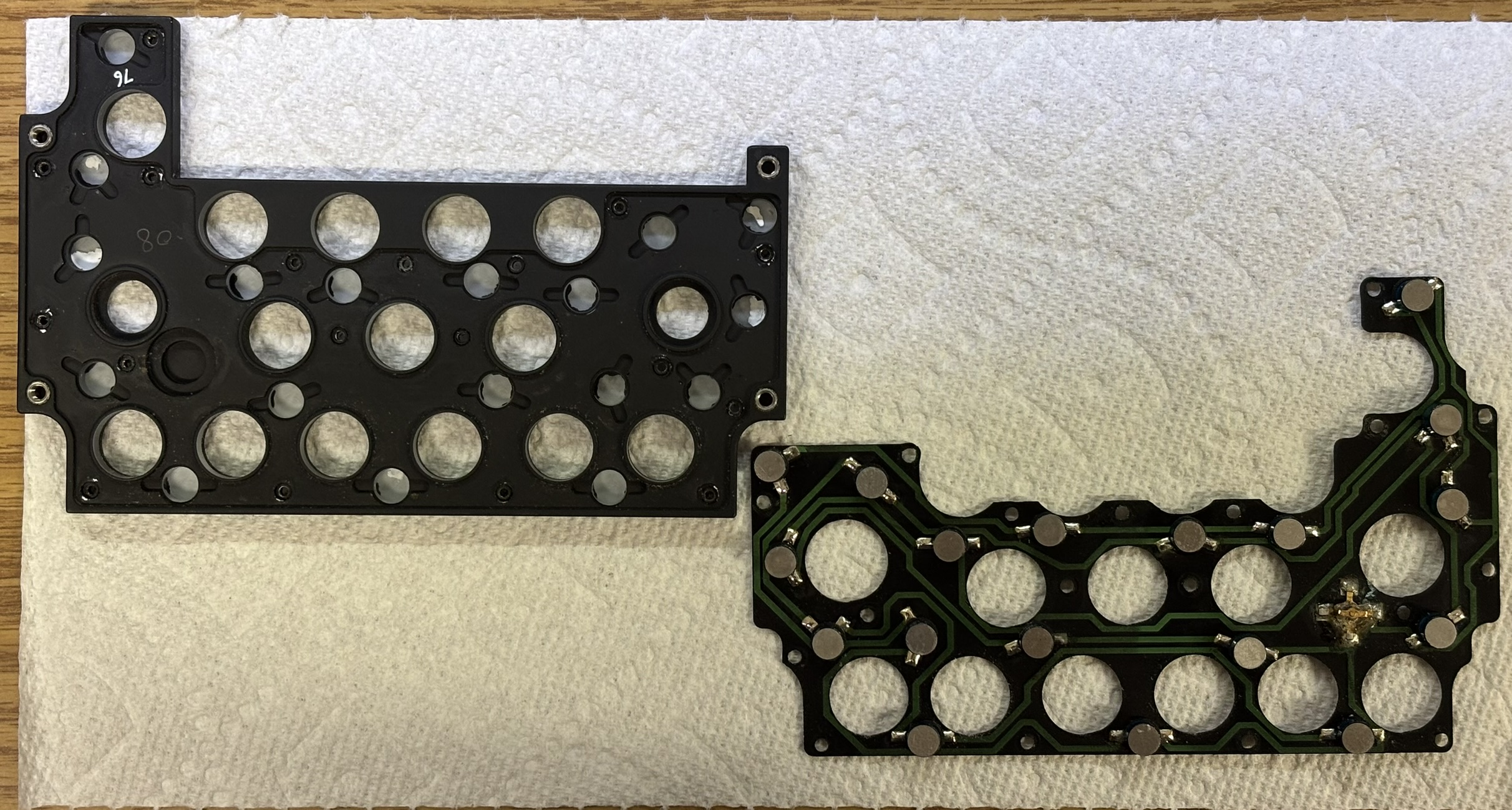
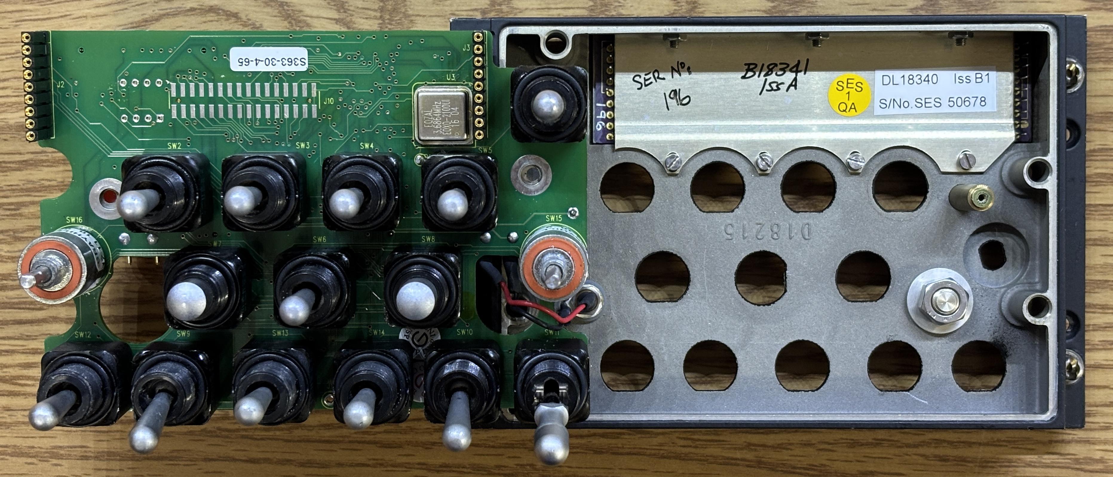
The front control panel is secured to the rest of the casing by 4 hex screws. Once removed, it can be pulled away from the casing. It connects via a dual-row pin header. The image below is of the back side of the control panel. All the switches and controls are soldered to a PCB that is referred to as the DISPLAY CONTROL & SWITCH CARD. The backlight connector uses two wires that are soldered to the PCB. The large nut is used to secure a blank plug in the front panel, likely for a switch or connector that is not applicable to this unit. The top-right dual-row pin header is used to connect to the remainder of the CDU. The dual-row pin header in the center of the board is not connected and may be used for diagnostic or programming purposes. The first IC on this board is an ST PSD954F2 in-system programmable peripheral for 8-bit MCUs. Next is an Infineon SAF-C164CI-LM 16-bit MCU. Other than that, there are just some surface mount capacitors and transistors on the board.
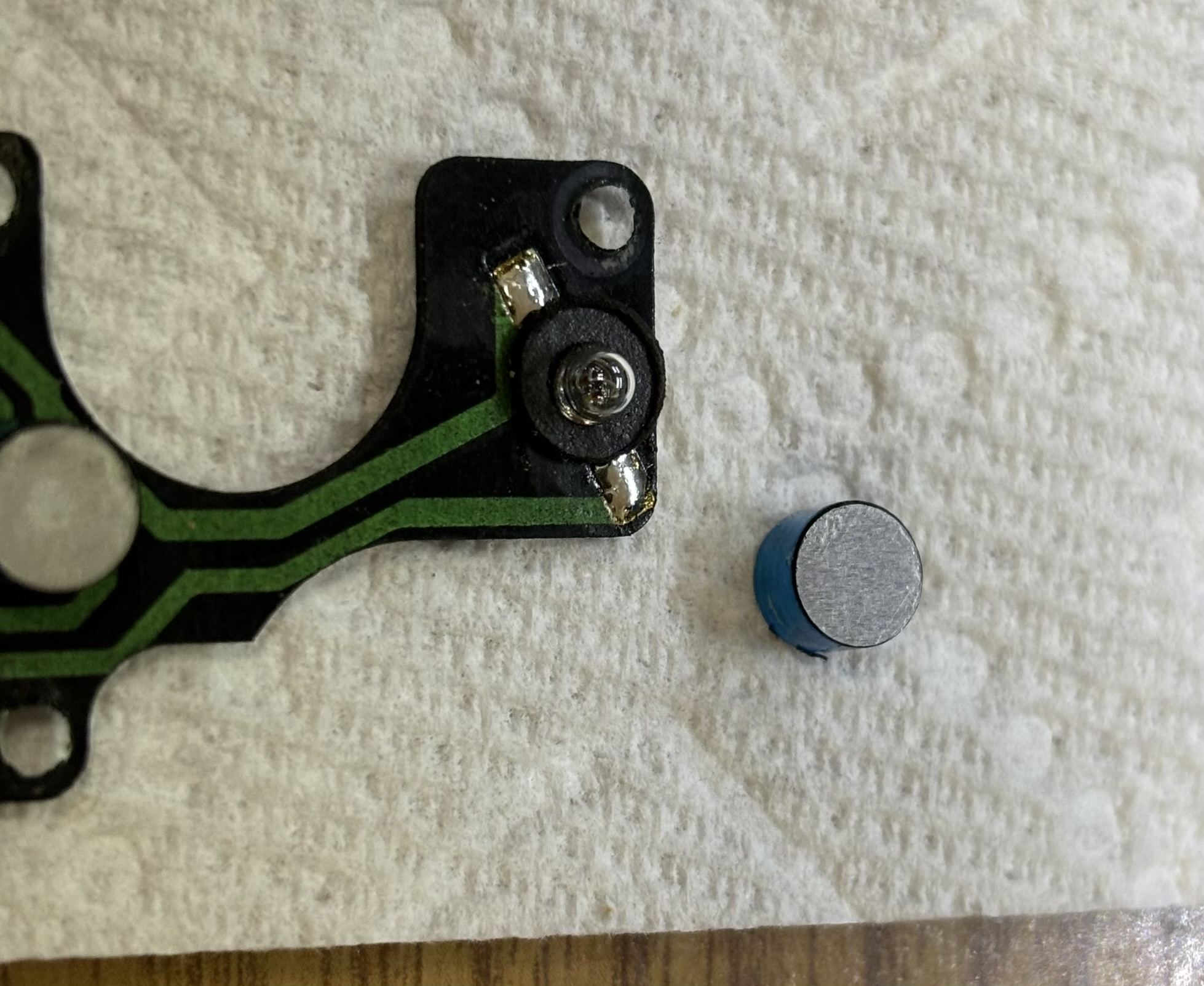
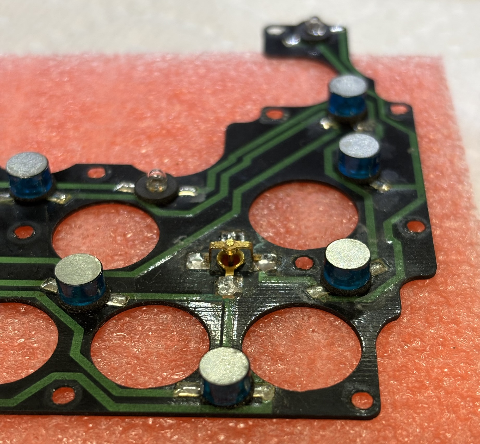
The display control and switch card PCB can be removed only after painstakingly unscrewing all of the retention nuts for the toggle switches, buttons, and rotary switches. After that, removing the two screws on the back allows the card to be pulled away from the front metal frame. The display connects to the card via several pins that insert into headers on the board. Other than the switches, the only notable component on this side of the board is a 3.6864 MHz crystal oscillator.
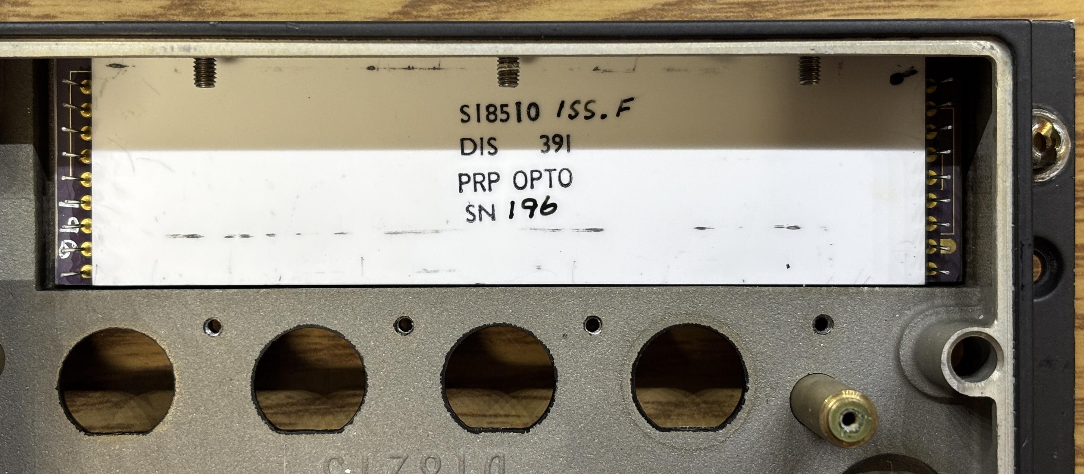
Removing the metal bracket reveals the back of the display. It's a ceramic package that was manufactured by PRP Optoelectronics and has a pretty low serial number of 196. PRP Optoelectronics specializes in LED display technologies for various industries including defense and aviation. This particular display is a customized micro-LED display. The display appears to be bonded to the front window and could not be removed easily.
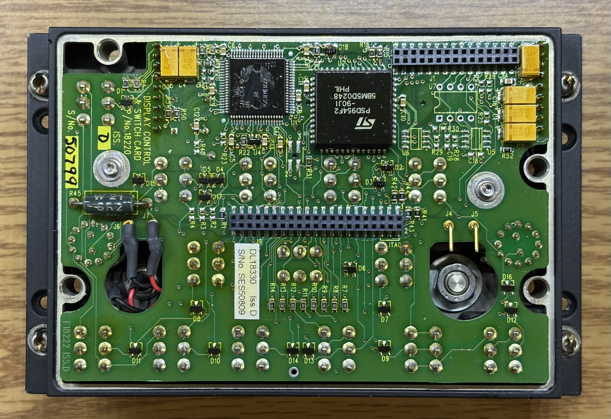
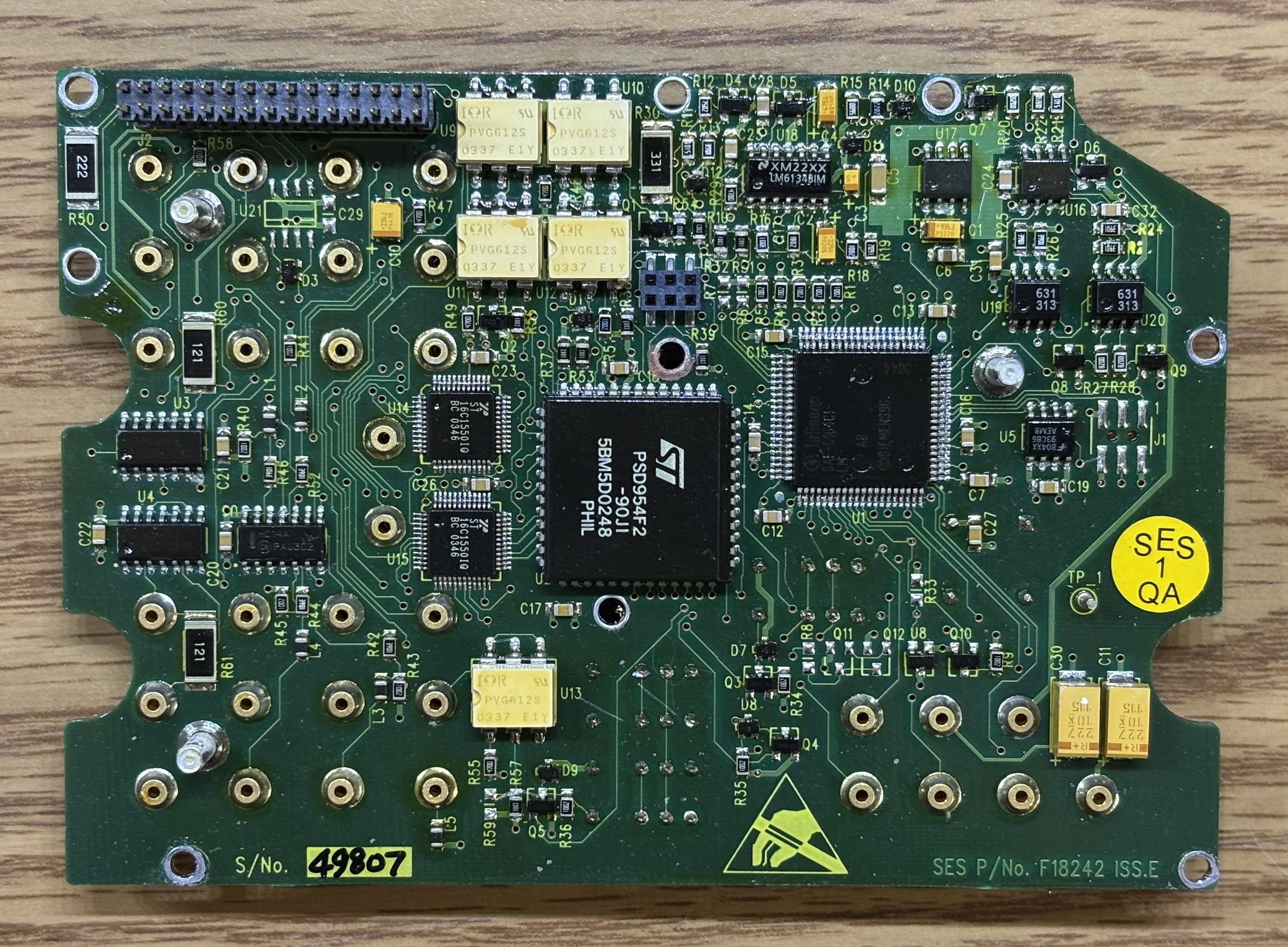
This this is the CDU motherboard. It is recessed into the outer casing and has a dual-row pin header that mates with a connector on the control & switch card. It is secured to the rear casing by metal standoffs and small nuts.
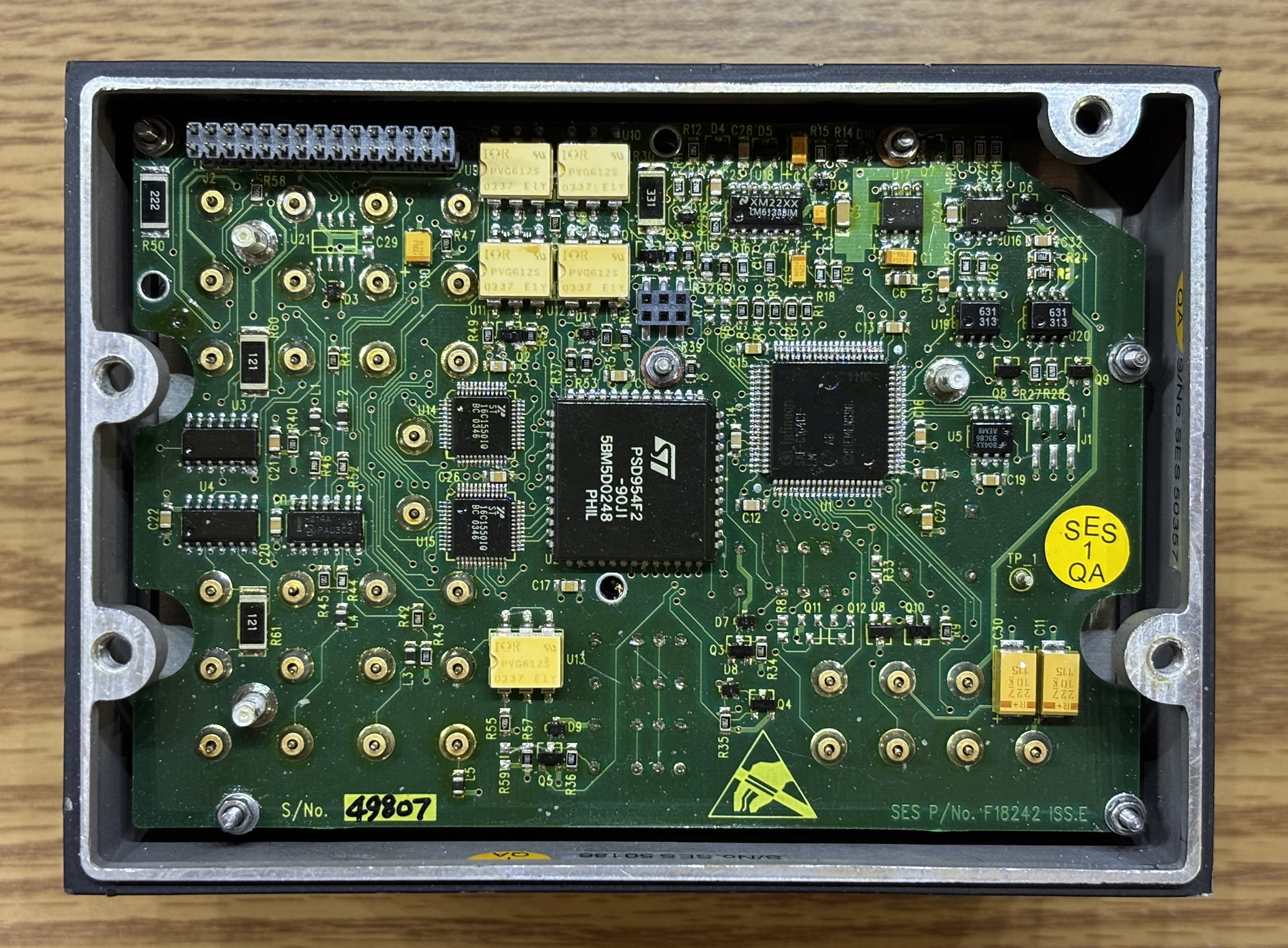
On this board is another ST PSD954F2 peripheral chip and an Infineon SAF-C164CI-LM MCU, just like the control & switch card. The white surface mount components are IOR PVG612S photovoltaic (solid state) relays. Lastly, there is a pair of ST16C1550IQ UART chips, a serial EEPROM, and some miscellaneous logic.
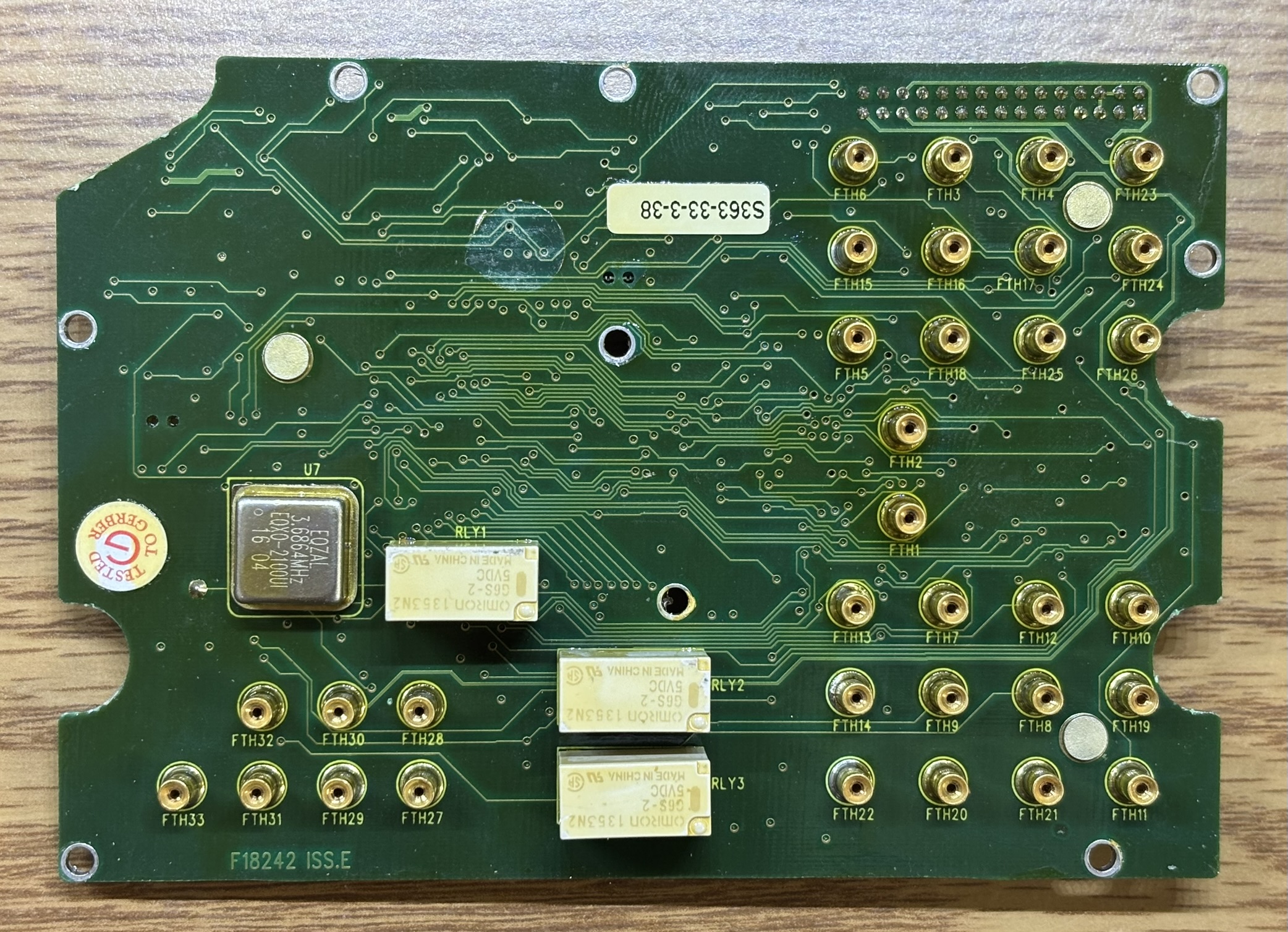
On the back of the CDU motherboard is a 3.6864 MHz crystal oscillator and 3 Omron G6S relays. Also, there are a total of 33 press-fit pin sockets or "feed throughs". These sockets accept a pin being inserted and make contact using only friction. They are actually quite reliable and favored over many other connector types in critical components that are subject to significant amounts of vibration. There are 3 threaded studs on the reverse side that are used to pull the board off of the press-fit pins.
Removing the CDU motherboard reveals two covers that are installed into the rear section of the metal housing. Male press-fit feedthrough pins are installed in an arrangement that matches up with the sockets on the motherboard. Each cover is secured to the outer casing with small screws and some metal standoffs used to support the motherboard.
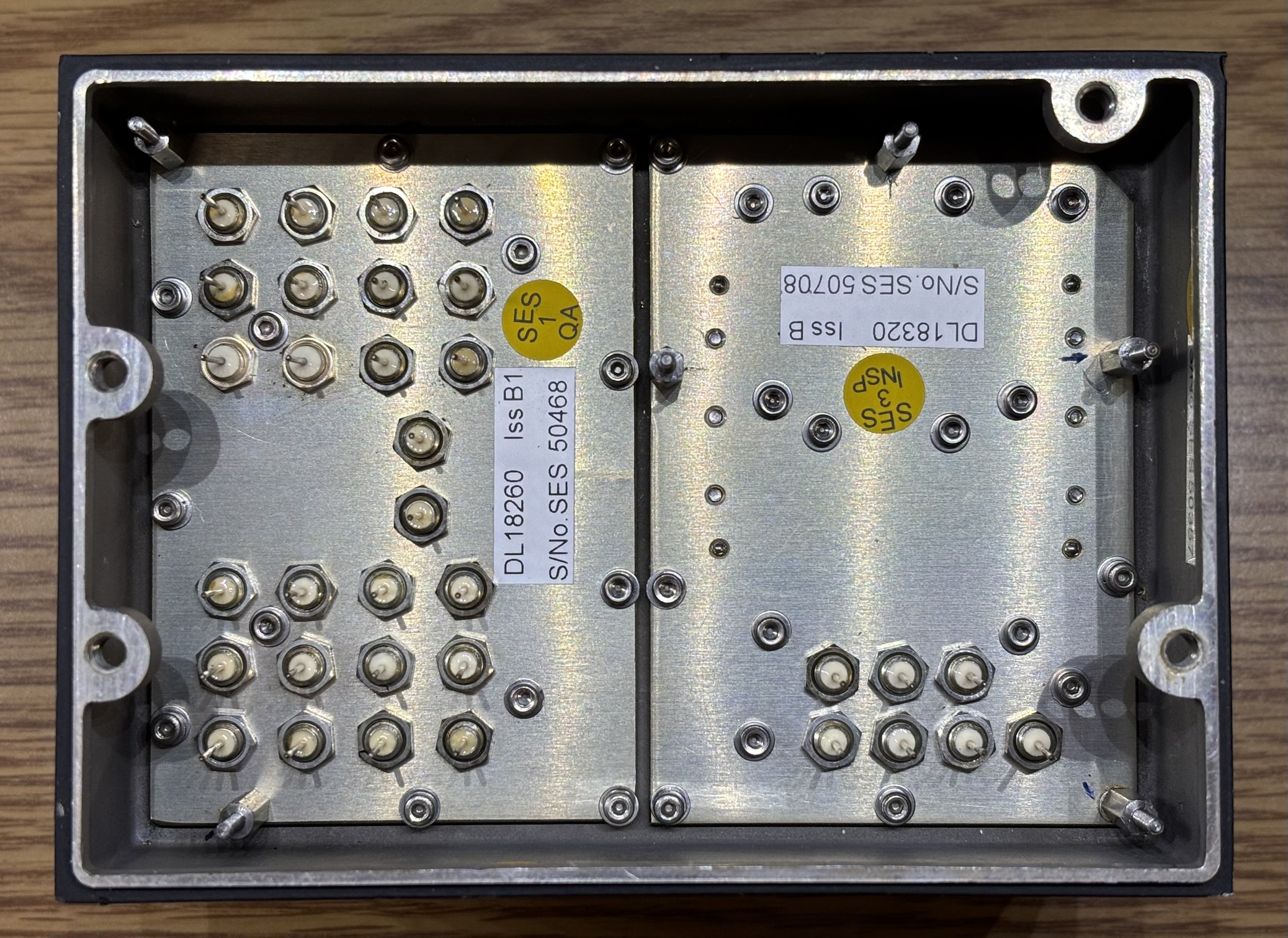
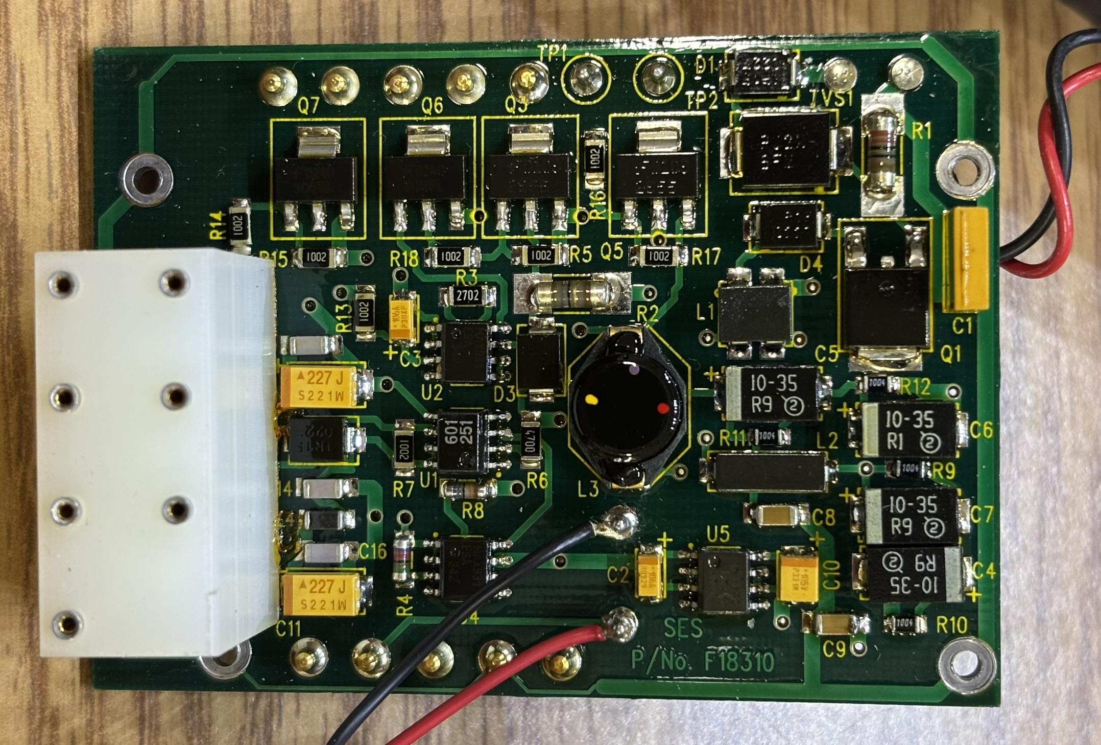
Behind the right-side cover is the DC-DC converter and power supply distribution board. This board is connected via 2 wires to the other side.
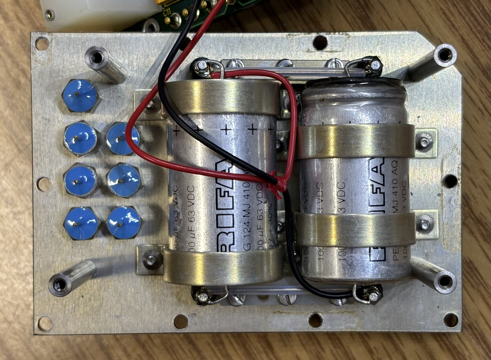
This is the back side of the power supply distribution board which connects to the DC-DC converter module. The pins from the DC-DC converter insert into the metal sockets along the sides of the board.
The power supply distribution board is secured to the metal plate with some standoffs.
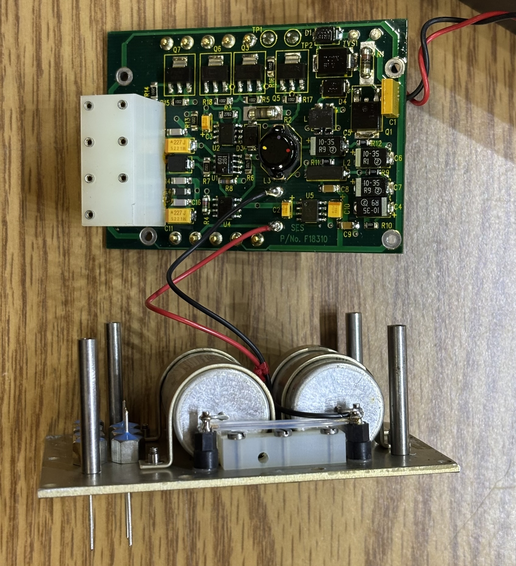
The power supply distribution board. It breaks out the connections on the DC-DC converter and also accepts press-fit pins that go to the CDU mainboard.
Mounted to the metal plate are two RIFA PEG124MJ410AQ capacitors connected to the input side of the power supply, likely to smooth out the input power. The blue components next to the capacitors are press-fit feedthrough pins screwed into the metal plate. They are double-sided and connect the power supply distribution board to the CDU motherboard.
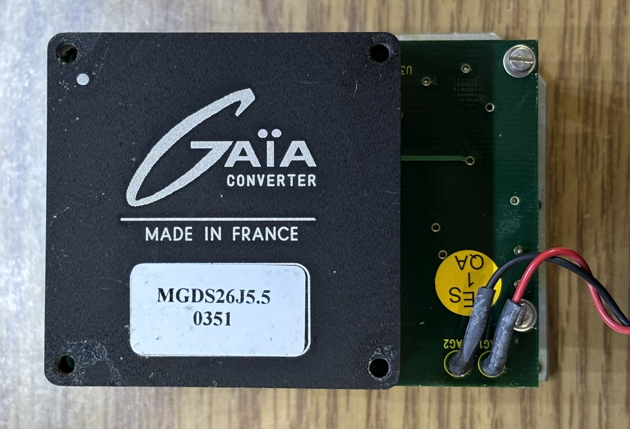
This is the DC-DC converter which is secured to the back of the outer metal enclosure by 4 screws. It is manufactured by GAIA of France and has the part number of MGDS26J5.5 (MGDM-26 series). It accepts 16-40 V DC as the input voltage and outputs 5V DC. The DC-DC converter is able to supply a maximum of 25 watts of power.
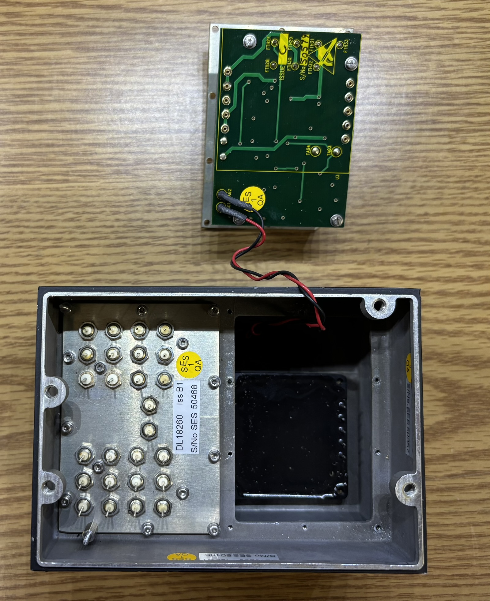
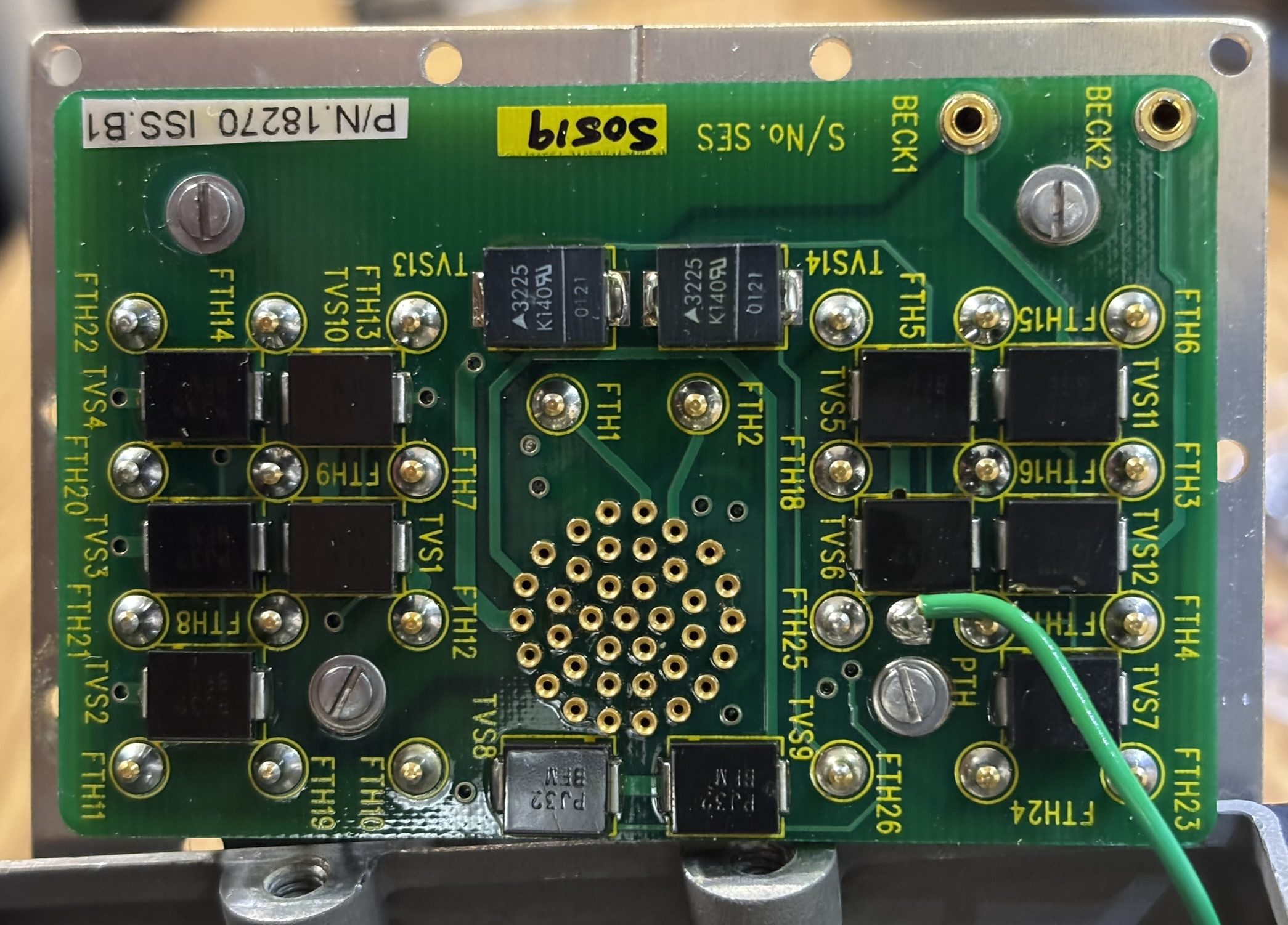
Removing the left side metal cover reveals a circuit board mounted to it via standoffs. This is the interconnect board that breaks out the connections from the twist-lock connector on the back. Press-fit pins are then used to transport these connections to the CDU motherboard. There are several surface mount TVS (transient voltage suppression) protection diodes on this board. Also, there is a dedicated ground connection that is screwed to the rear of the casing and soldered to the breakout board.
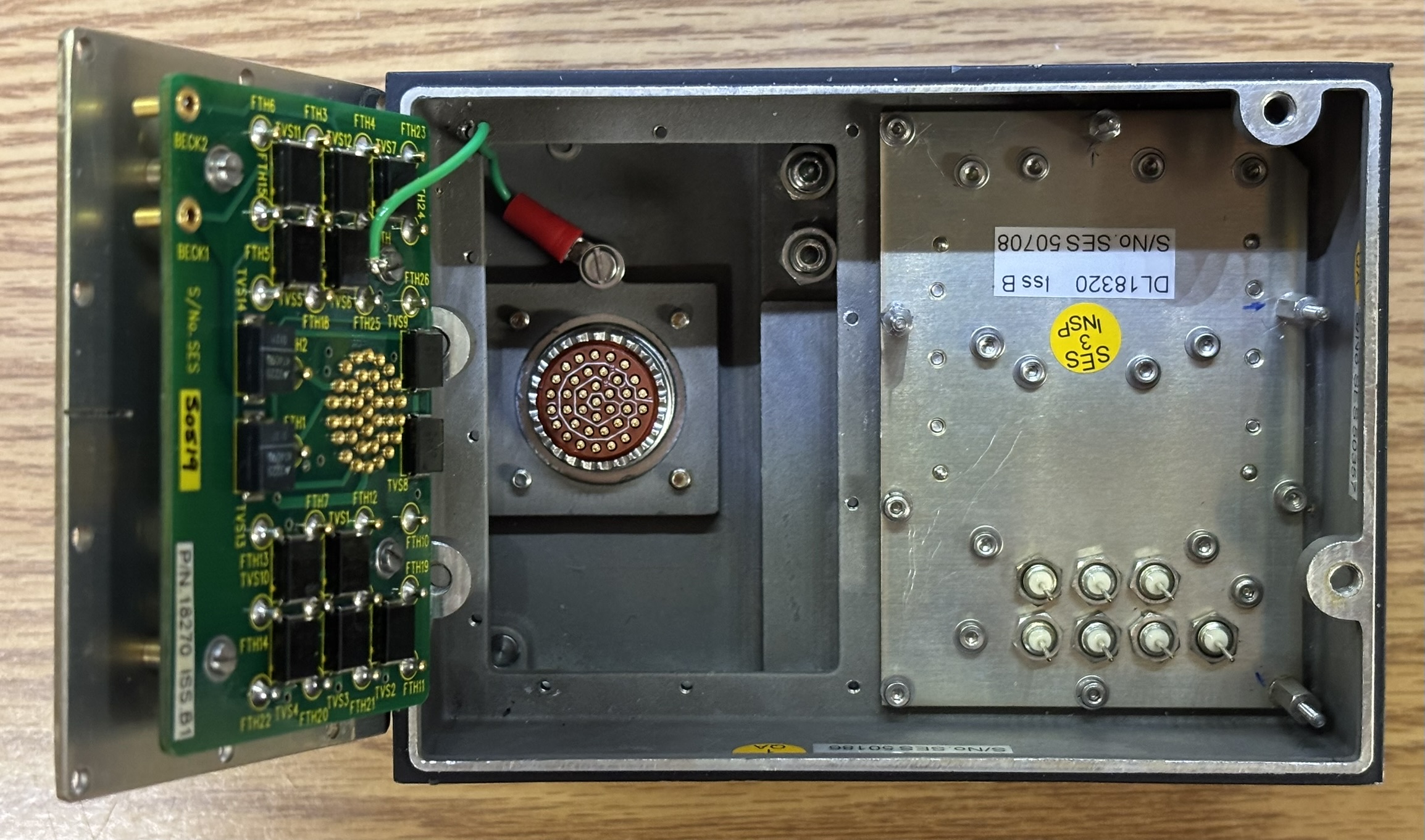
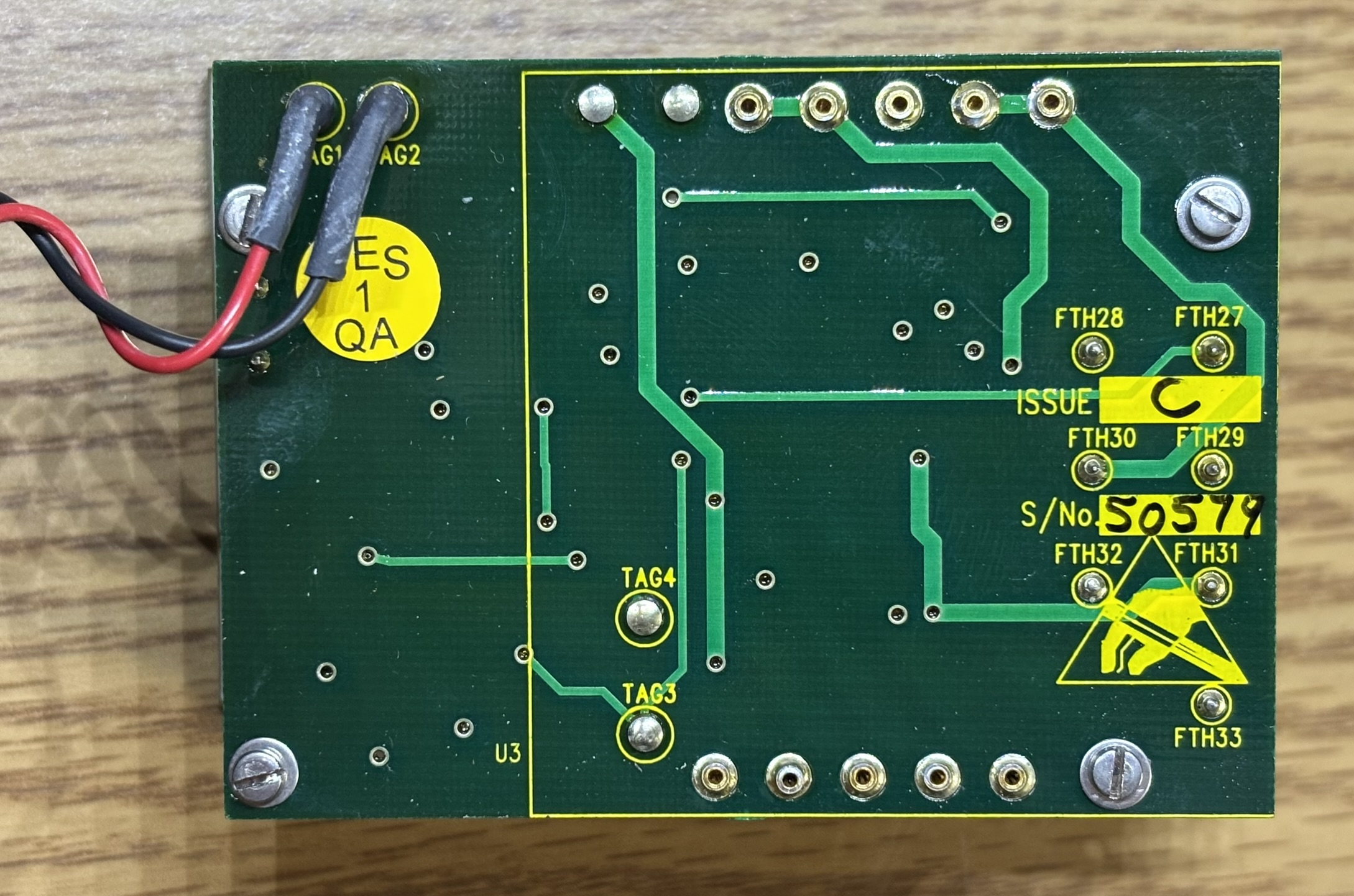
In the image below you can see the gold sockets that the pins from the rear twist-lock connector insert into when the board is installed. As mentioned earlier, there are several TVS diodes that protect the sensitive components from voltage spikes. The connector is broken out to several feed-through sockets that accept the press-fit pins on the reverse side of the board. Take note of the two press-fit pin connectors labeled BECK1 and BECK2. These seat into pins mounted to the casing. These pins are the input pins for the DC-DC converter behind the cover on the other side.
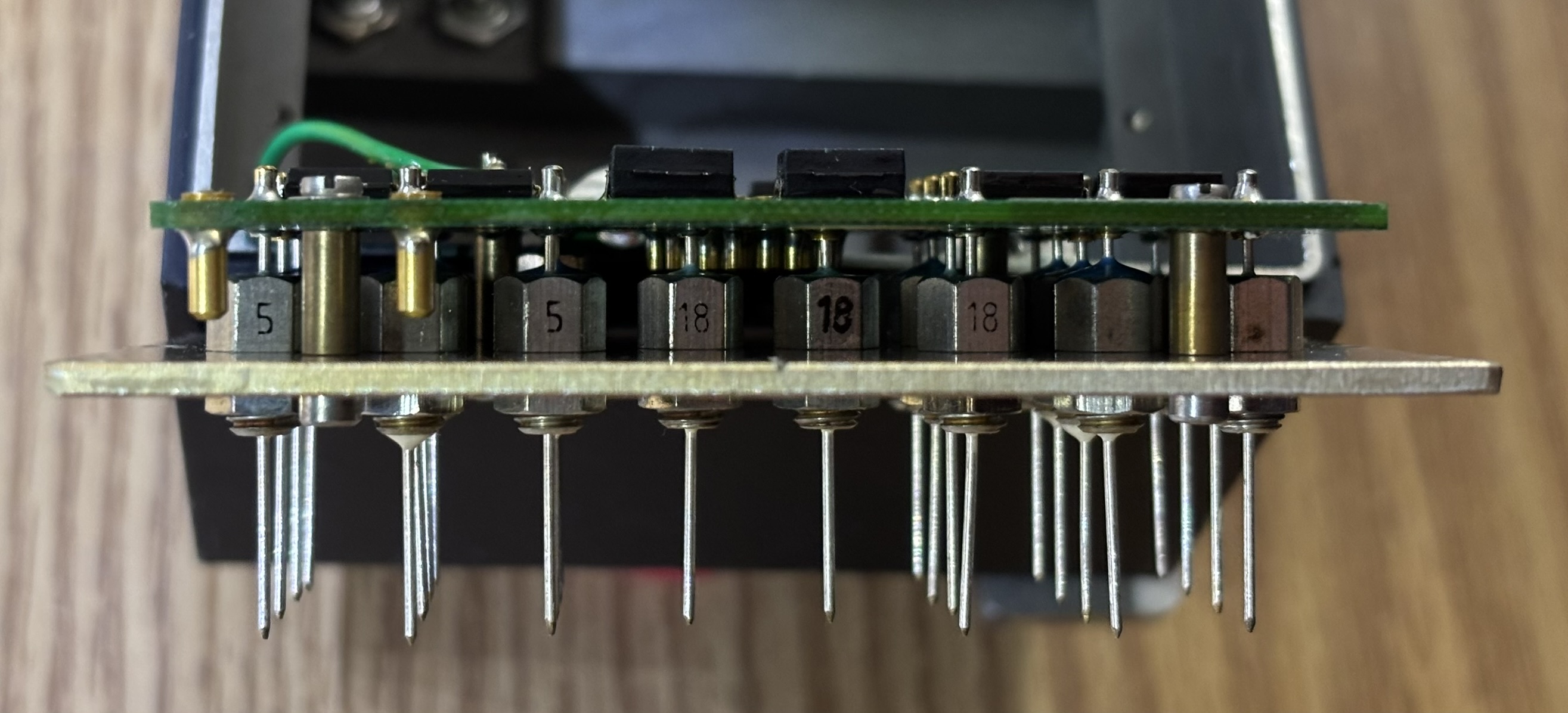
Here is a side view of the press-fit pins.
This unit runs on 24-28 V DC, common with many commercial and military aircraft. Applying 28 V DC to PIN 35 and using PIN 36 as a ground will allow the unit to be powered on. The MASTER switch must be in any position other than OFF for the system to turn on. The backlight uses a different set of connections, PIN 15 and PIN 16. Applying 28 V DC will operate the backlight at maximum brightness. A lower voltage can be applied to dim the backlight. An abbreviated pinout has been provided below this image.
Here is the pin-out for the 37-pin connector on the back of the CDU. Unused or unknown pins were omitted. The SIFF 4870 has a variety of connections that include DC power, backlight control, display dimmer, lamp test, relay outputs, digital inputs, and two RS-485 channels for full duplex communication. Due to lack of available information, we are not sure what each connection is for, but we expect at least one of the relays is used to turn the transponder on and the RS-485 channels are used for data exchange between the transponder and CDU.
| PIN | DESCRIPTION |
|---|---|
| 1 | RELAY OUTPUT |
| 2 | RELAY OUTPUT |
| 3 | RS-485 |
| 4 | RS-485 |
| 5 | DIGITAL INPUT |
| 6 | DIGITAL INPUT |
| 9 | RELAY OUTPUT |
| 14 | RELAY OUTPUT |
| 15 | BACKLIGHT POSITIVE (MAX 28V DC) |
| 16 | BACKLIGHT GROUND |
| 18 | RELAY OUTPUT |
| 19 | DIMMER INPUT (MAX 28V DC) |
| 20 | LAMP TEST (GROUND TO ACTIVATE) |
| 25 | RS-485 |
| 26 | RS-485 |
| 27 | DIGITAL INPUT |
| 28 | LOGIC/DIGITAL GROUND |
| 31 | RELAY OUTPUT |
| 33 | DIGITAL INPUT |
| 35 | POWER INPUT (MAX 28V DC) |
| 36 | POWER GROUND |
| 37 | FRAME GROUND |
Since this unit is expecting to communicate with the transponder system over RS-485, it displays an "I/F FAIL" error message once the self-test completes. At this point the unit does not really do anything else. Pressing the test button will re-execute the self-test and moving the master selector to off will turn the unit off. None of the other controls have any visible effect at this point. However, when probing the RS-485 interface, changing switch positions does have a visible effect on the output data stream. We have not yet figured out the proper syntax to understand the serial data or send commands to the unit that it will understand.
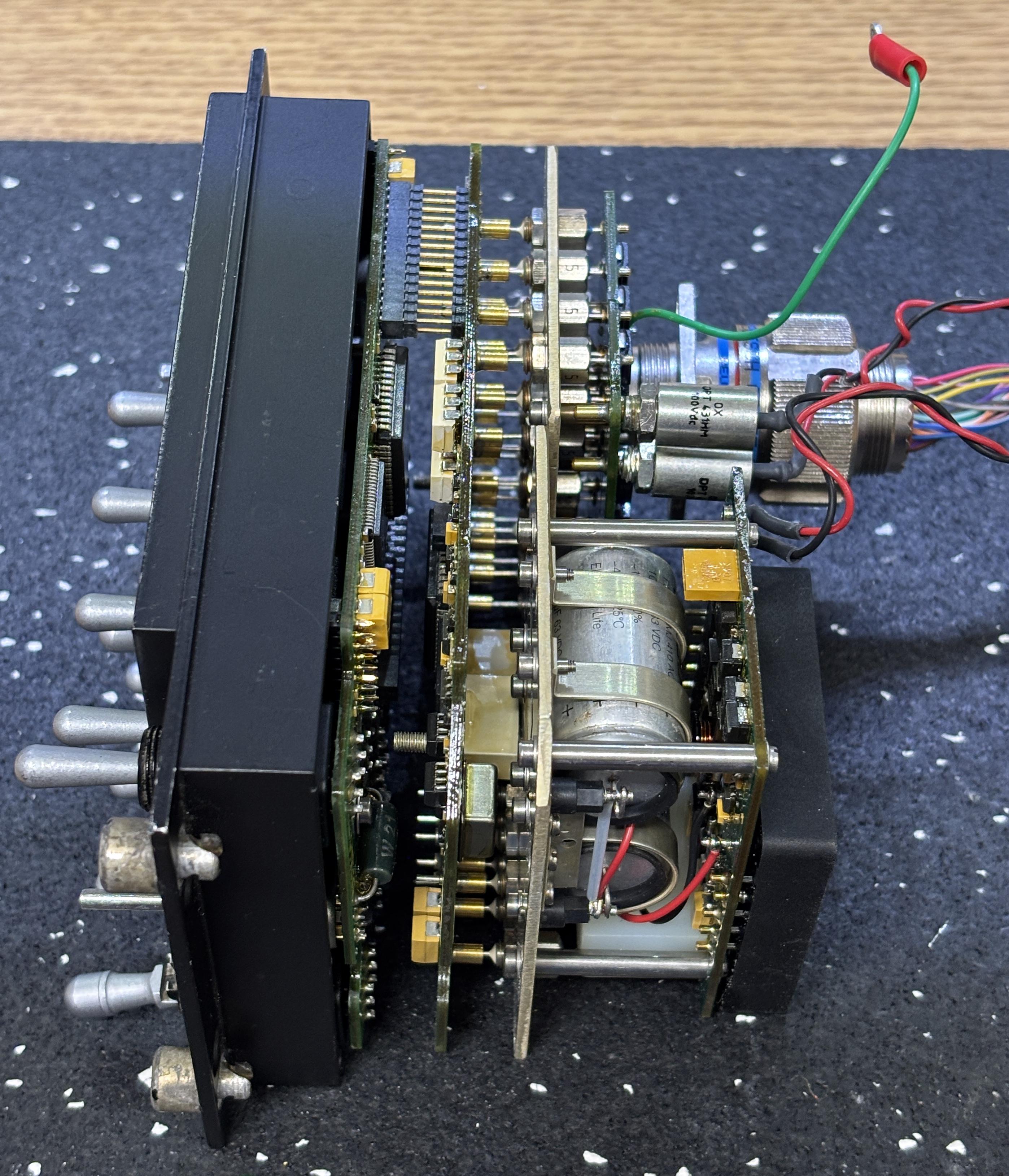
Here is an image of the boards removed from the casing, but connected exactly as they would be if they were installed in the casing. It's a stacked arrangement with controls and display in the front, the processing and relay board in the middle, and power conversion in the back.
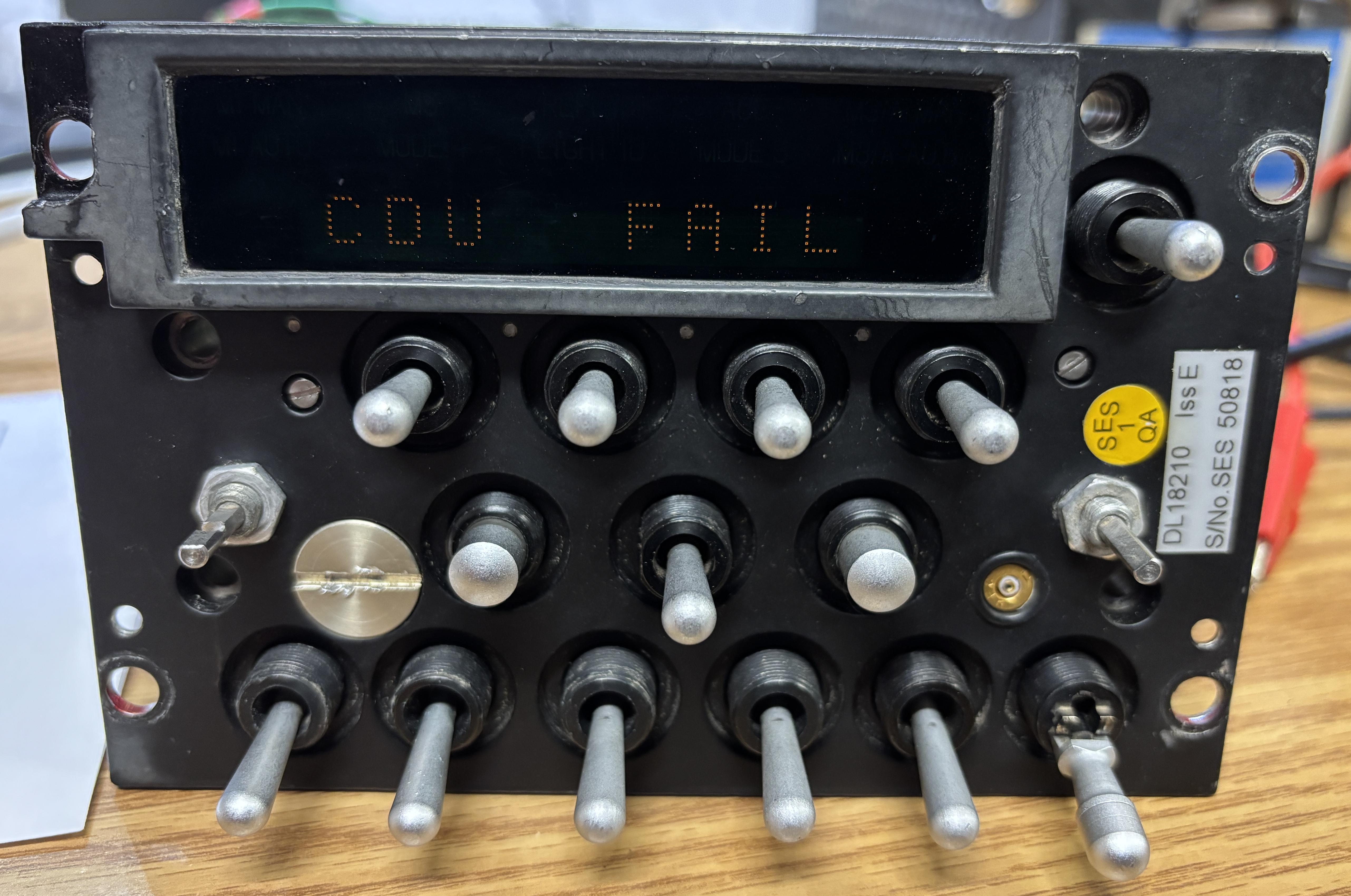
As a final experiment, we powered up just the display control and switch card (front section) without it being connected to the CDU mainboard and remaining components. Unsurprisingly, it just dimly displayed a message that read "CDU FAIL" and refused to do anything else.
Check out Michel's video on his YouTube channel (Le labo de Michel) where he examines and deciphers the connections for the SIFF 4870. He also created some useful diagrams that helped us get this unit connected.