The SELL 64763-001-003 "Beverage Maker" is the most over-engineered coffee maker we have ever seen. Since it's designed to be installed in the galley of a commercial passenger plane, like the Boeing 727 or Airbus A320, it must be built to meet aircraft reliability and safety specifications. The design of the galley coffee maker dates back to the origins of passenger air travel. People have been drinking coffee since the 15th century, and many rely on it to stay awake and alert throughout the day. It only makes sense that passengers traveling by plane should have access to some freshly-brewed coffee. Thus, the galley coffee maker was created. It functions just like a traditional coffee maker, but has some interesting bonus features and also features an impressive level of component build quality.

Overview
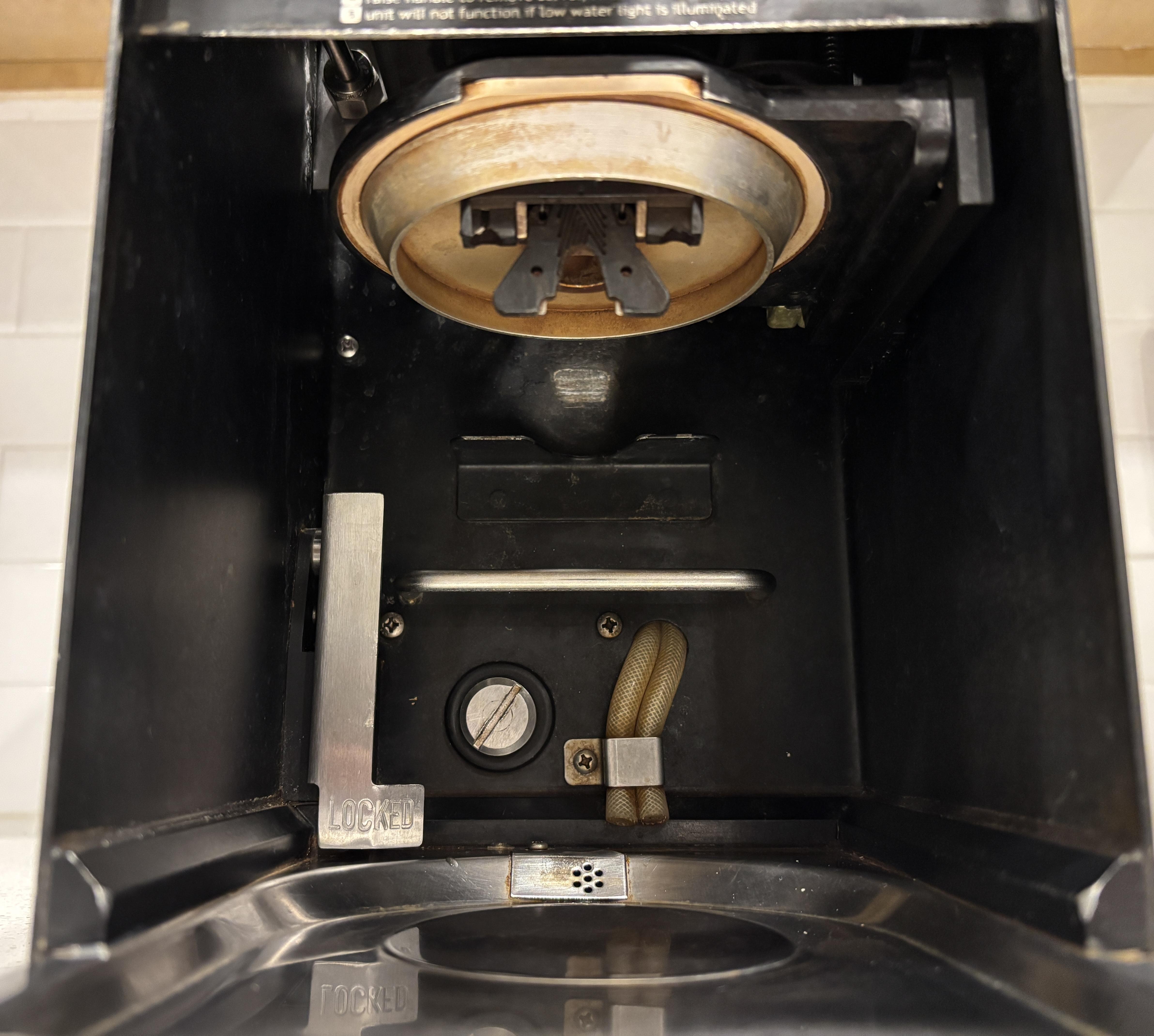
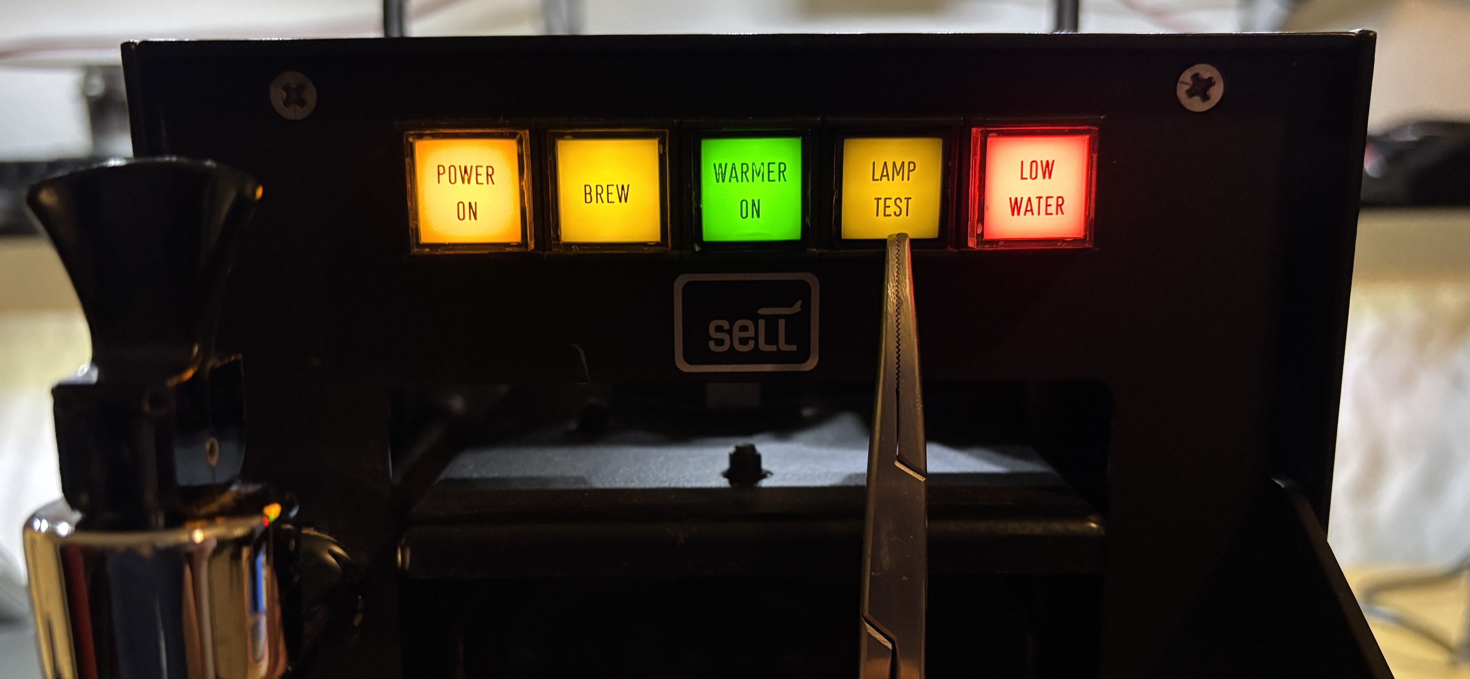
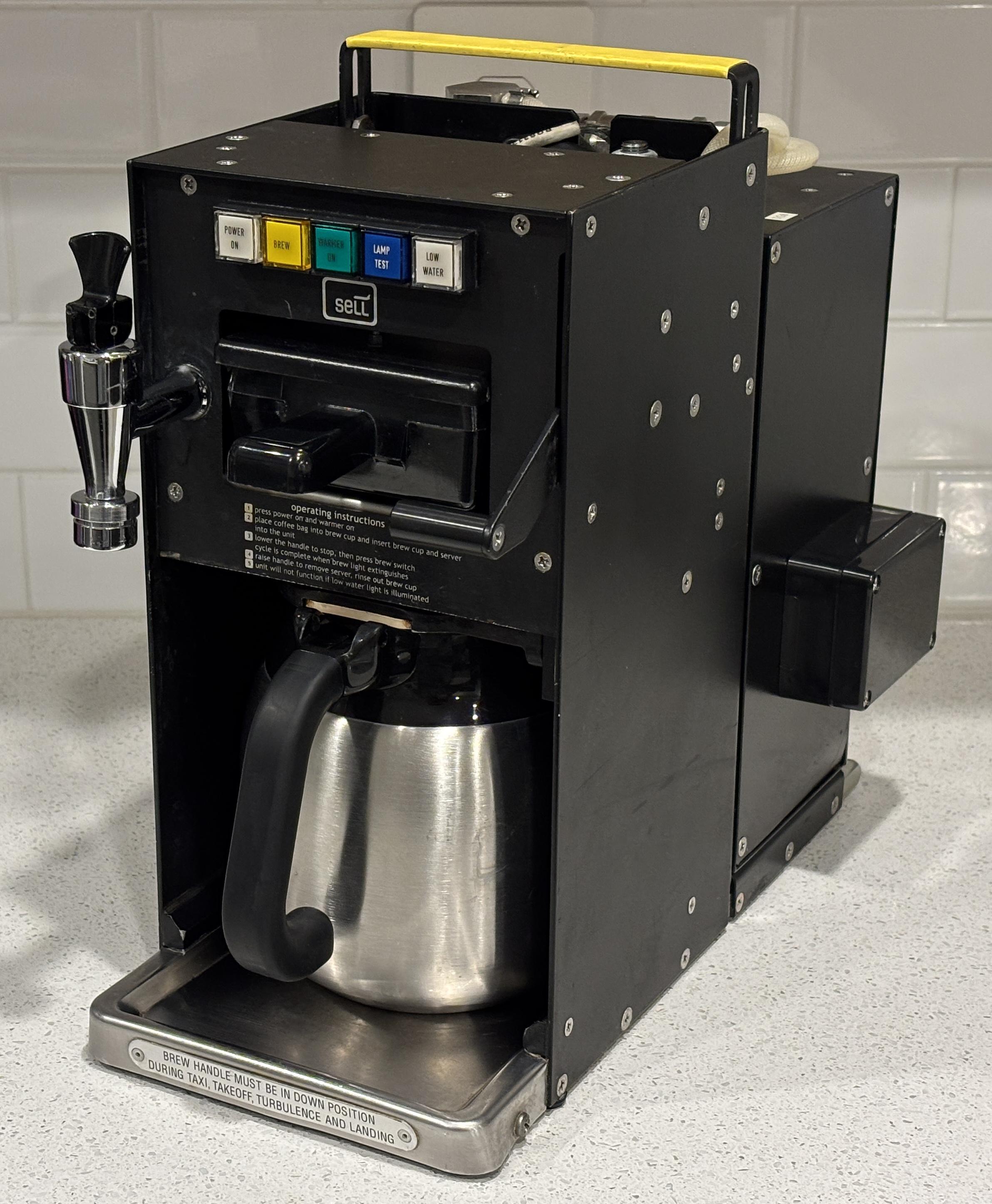
Taking a look at the front of the unit, it's hard to even recognize what it is with the coffee pot (or carafe) removed. But if you look closely at the operating instructions and the BREW button, it becomes apparent that it's a coffee maker. On the top is a row of high quality illuminated pushbuttons that are used to operate the machine. The POWER ON button enables the control power and water tank heating elements. Once the water is heated sufficiently, the BREW button can be pressed to activate the solenoid and dispense hot water from the tank, through the tray containing the coffee grounds and filter, and into the coffee pot. The WARMER ON button enables a heater on the bottom of the unit to keep the coffee in the pot warm and ready to be served. The LAMP TEST light is probably the most hilarious feature to see on a coffee maker. This is an obvious sign that it's an aircraft design as many avionics components require the implementation of a lamp test function that is used during maintenance. Pressing the LAMP TEST button will illuminate all the indicator bulbs so burnt out ones can be identified and replaced. Last is the LOW WATER indicator lamp (not a button). If the water tank is not filled sufficiently, this indicator will illuminate and the heating elements will be disabled to prevent damage. On the left side is a faucet that dispenses hot water from the tank into a cup placed below. This is common with commercial coffee machines that are connected to a water source. In the middle below the SELL logo is the brew basket, a removable tray in which the coffee grounds and filter go. On the right side is a black handle that can be pulled down to lock the brew basket and coffee pot into place. This is another aircraft-specific feature as you cannot have hot coffee escaping from the pot and posing a safety hazard during turbulence. The information plate on the bottom explains the situations in which the handle should be locked into position. There is also a microswitch that will prevent brewing unless the handle is moved downwards to the locked position.

On the bottom half of the unit there are more interesting features. In the back behind where the coffee pot would be is a handle. Next to the handle is a metal lever that reads LOCKED. This lever controls a pin that extends downwards from the bottom of the machine. When the lever is moved up and the pin is released, the handle can be used to pull the entire coffee maker out of a slot in the galley. This allows the coffee makers to be removed and replaced easily. The device is a slot-in unit with quick-disconnects for the water and a plug for the electrical. Instead of being permanently integrated into the aircraft, they can be easily swapped out for cleaning, maintenance, or upgrades. It's also worth noting that these coffee makers do seem to follow a standard. We found images of galley coffee makers from several manufacturers and they all use the same form factor and water and electrical connections. There are even aircraft-grade espresso machines! There are two tubes that allow excess water or pressure from the tank to drain onto the bottom plate, which then drains out the back. The large slotted screw is a plug that can be removed to drain the water tank. Quite a bit of sediment dripped out along with some water when we removed it.
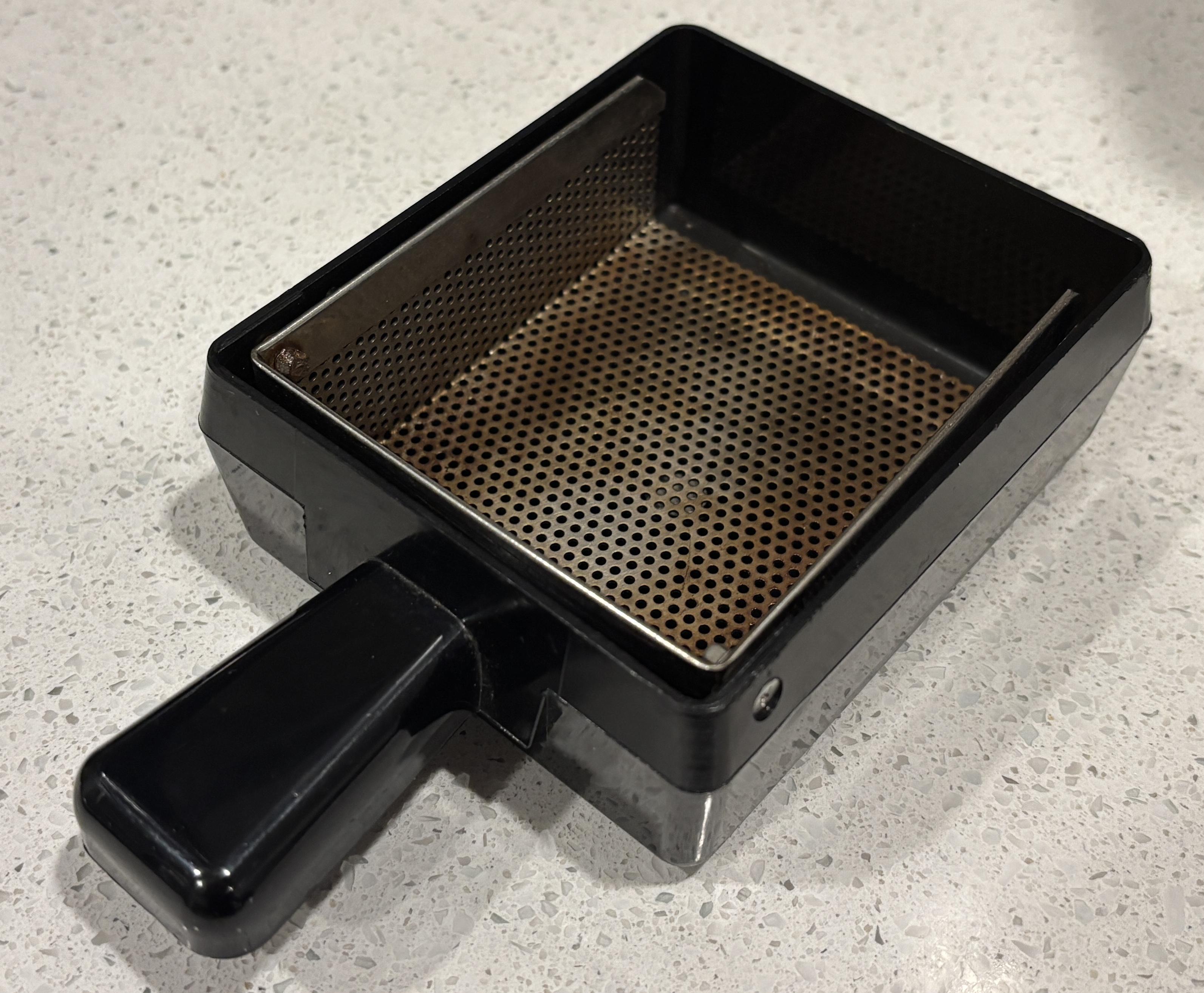
This is the brew cup where the coffee grounds and filter are placed. It has a metal mesh that hinges upwards for easy cleaning. The brew cup gets locked into place when the handle is moved downwards. A gasket on the top plate seals the brew cup from the top and a gasket on the bottom of the cup seals it to the bottom of the middle section. This prevents any leakage of liquid when the handle is secured.
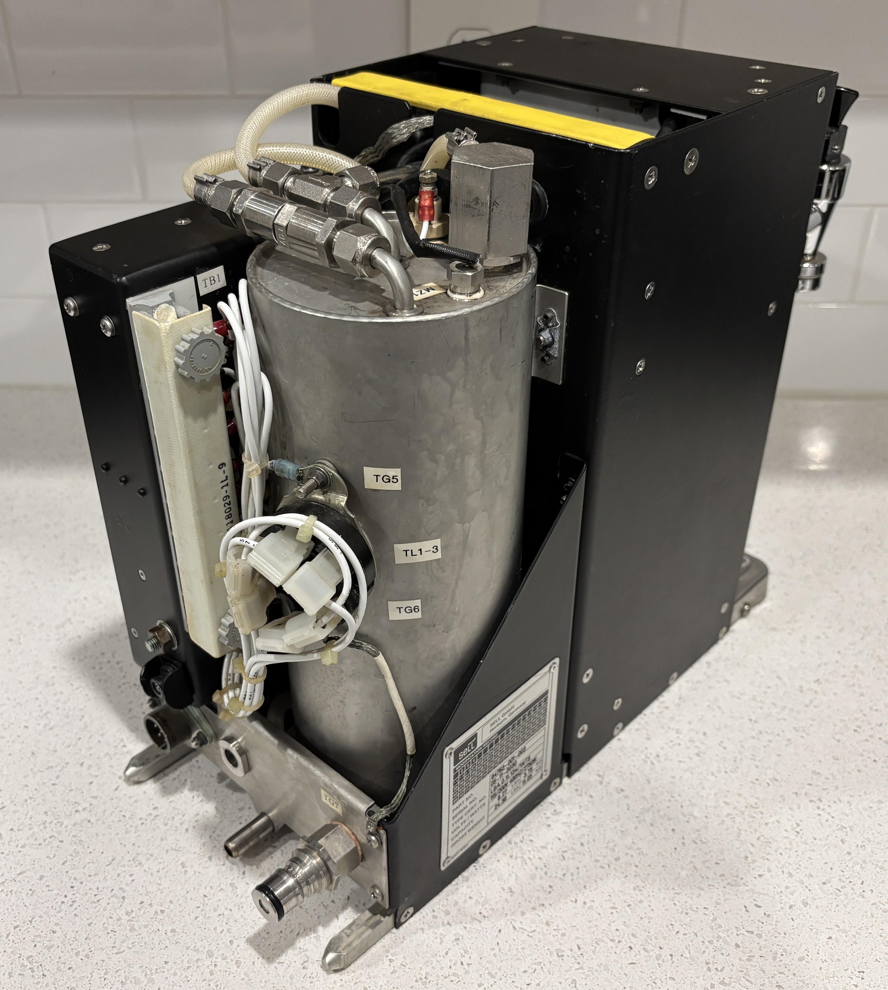
Located within the rear section of the coffee maker is the water tank, which is visible in the image below. It's a fully enclosed metal cylinder (likely stainless steel) that contains the heating elements used to bring the water up to a suitable coffee brewing temperature. It's essentially a miniature water heater. The water inlet is on the bottom of the tank and the outlets are on the top. There is also a drain plug accessible from the front. With 3 heating elements, it likely heated the water very quickly.
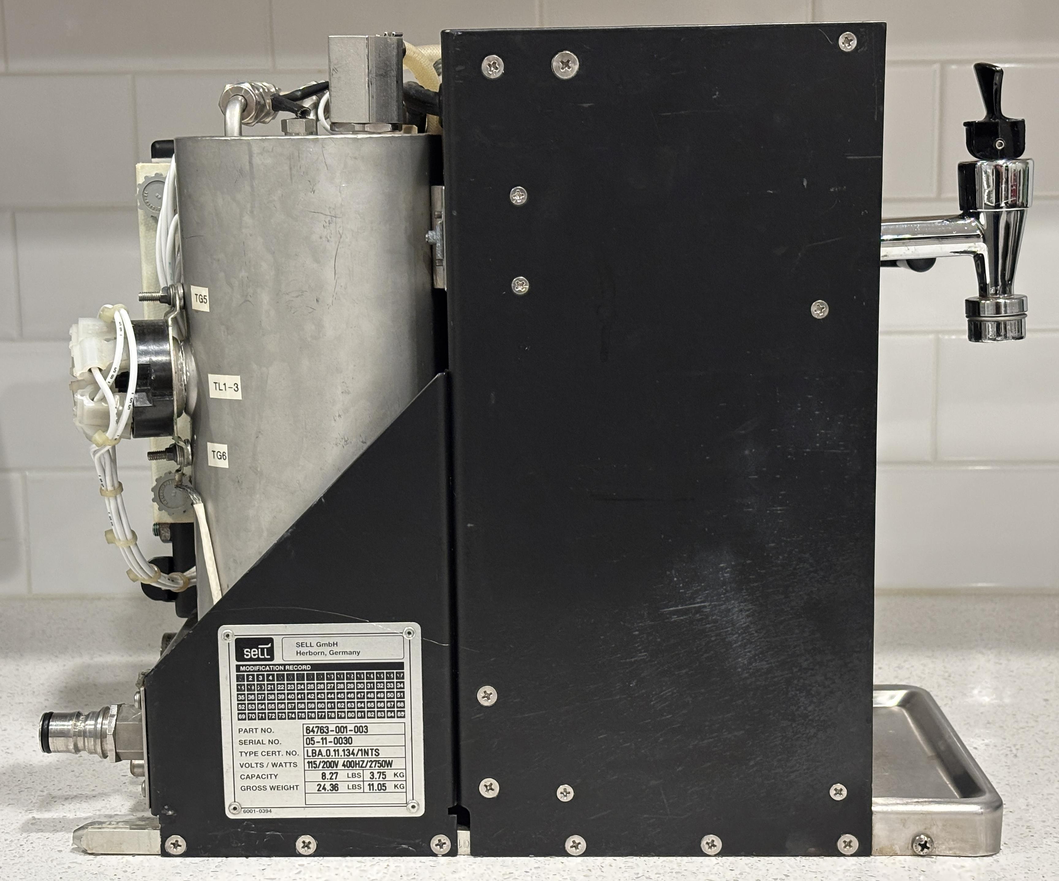
There's not much to see on the side of the machine other than the information plate. It lists the part number (67463-001-003), serial number, and type cert number (LBA.0.11.134/1NTS), along with the weight and electrical ratings. The system is capable of drawing up to 2750 watts of power, which is quite a bit!
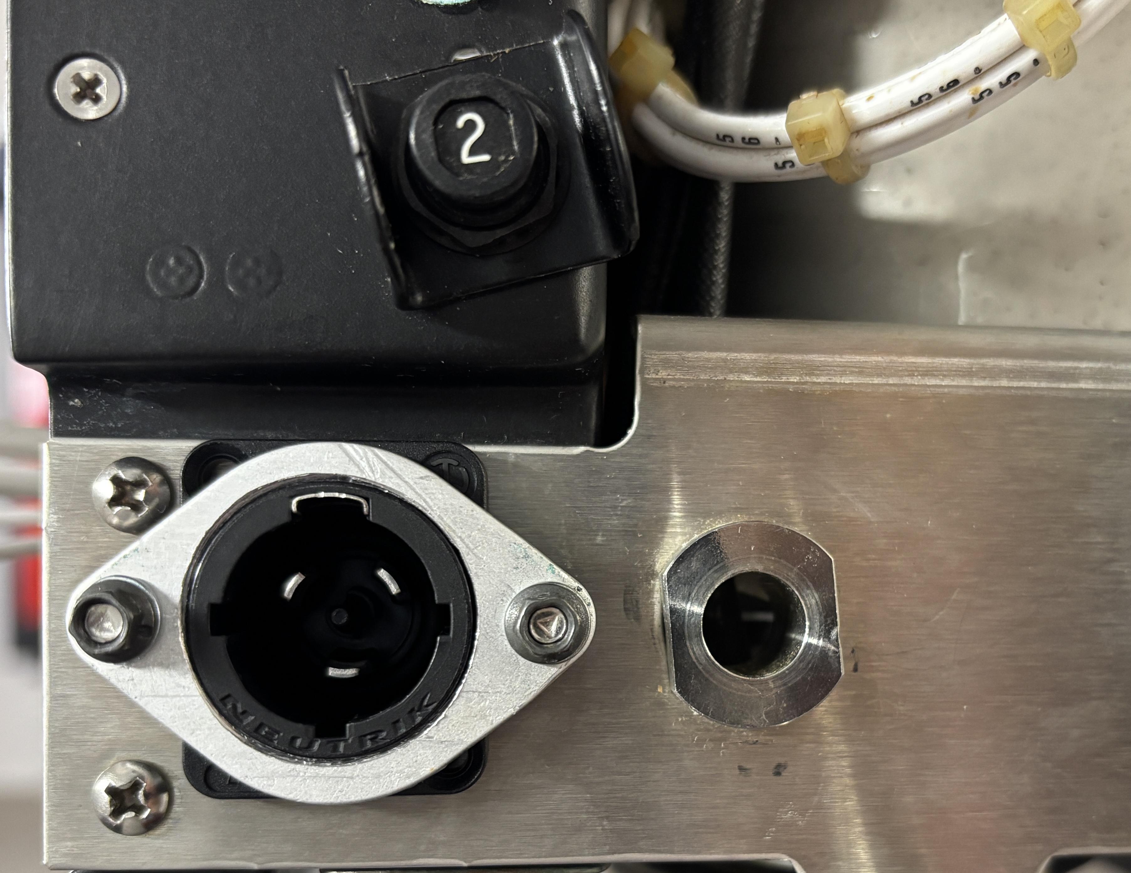
Here is the back of the machine. On the bottom left is the power connector. It slots into a mating connector when the machine is inserted into the galley slot. The electrical connections include 3-phase 115V AC power at 400Hz, a neutral, and a protective earth (ground). The other two pins are not used (or are additional grounds). Directly next to the power connector is a hole that accepts an alignment pin when the unit is inserted. Above the power connector is a 2 amp circuit breaker. On the bottom right is the water inlet connection, which is an Eaton Hansen 2KLF socket fitting with a built-in valve. On the bottom in the middle is the drain pipe.
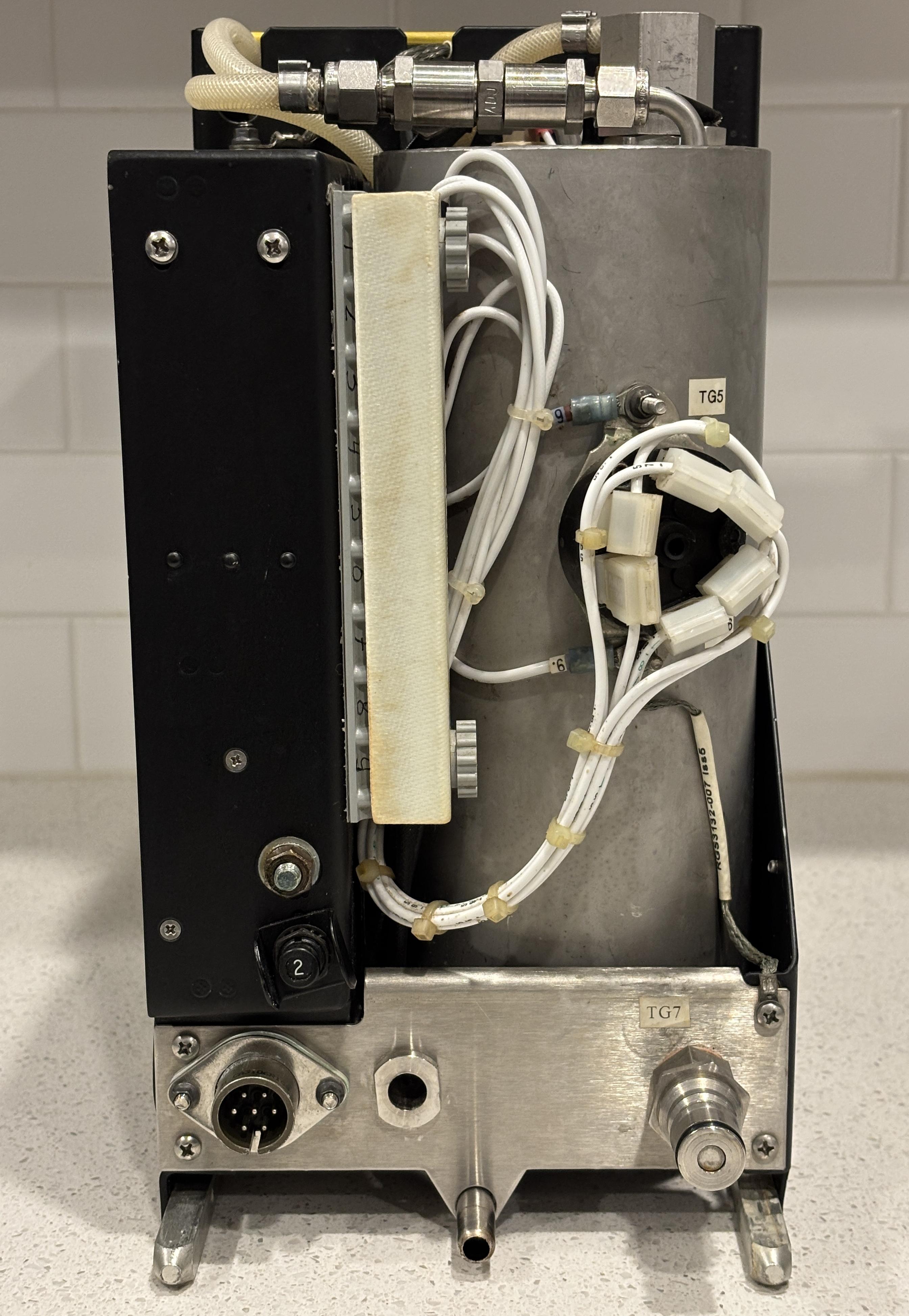
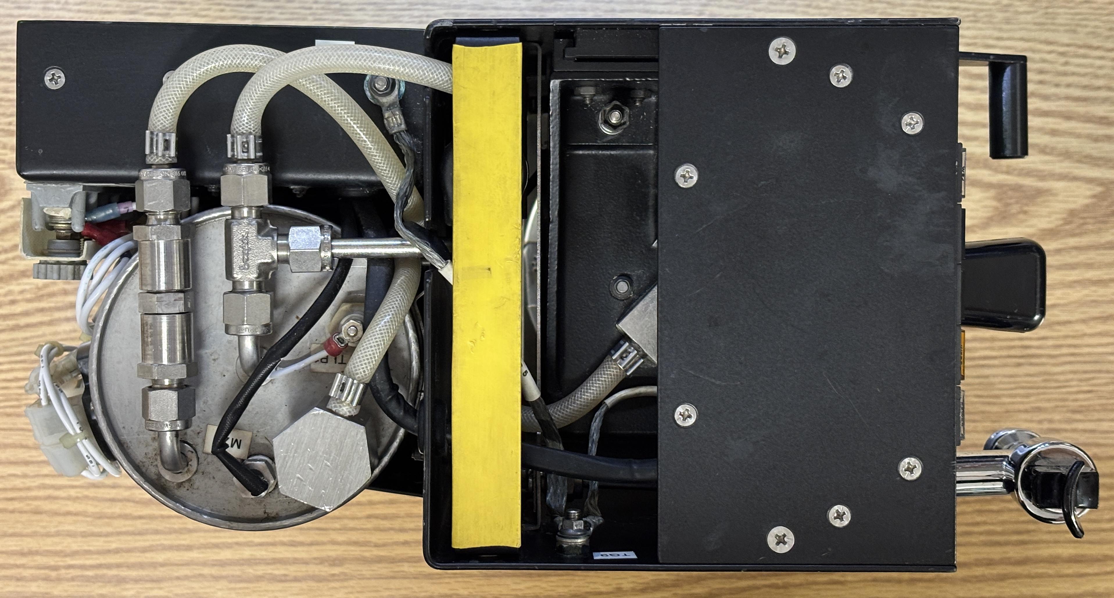
On the top of the machine is a retractable carry handle with a yellow plastic covering. This allows for easy transport and slides down into the frame when not in use. On the left side, the top of the water tank is visible, along with various plumbing and electrical connections. A tube exits from the hexagonal fitting and goes down to drain into the bottom tray. The tube from the leftmost fitting also goes down to drain into the bottom tray, this appears to be a traditional pressure relief valve. The hexagonal component is most likely a steam valve (based on our later disassembly) which ensures the tank can vent steam as the water boils and not explode. The T-shaped fitting has two tubes, one goes to the brew control solenoid, and the other to the hot water faucet on the front. There is a water level sensor installed in the tank and is labeled TLP1. Lastly, there is a thermal probe which is labeled MZ1.
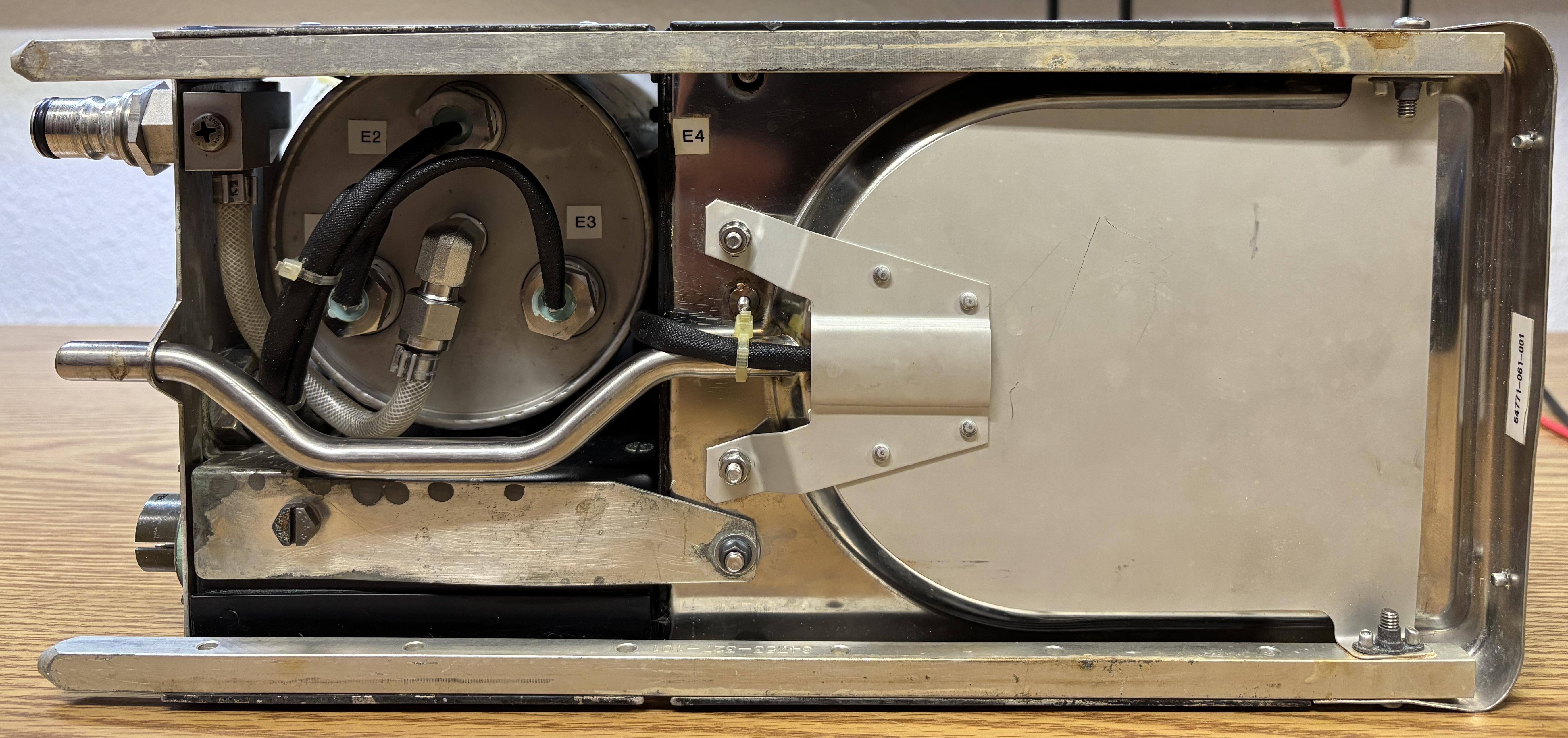
On the bottom of the machine are the two rails on either side which allow for insertion into the designated galley slot. The locking pin is visible right above the E4 label. The water inlet connection goes directly to a port on the bottom on the tank, which is then surrounded by the 3 heating elements. Below the tank is a stainless steel drain tube that connects to the aircraft's drainage system to get rid of any water that accumulates in the bottom tray. The pot warmer element (E4) is mounted directly below the bottom tray where the pot rests. The electrical connections are visible as they exit near the drain tube.
Technical details
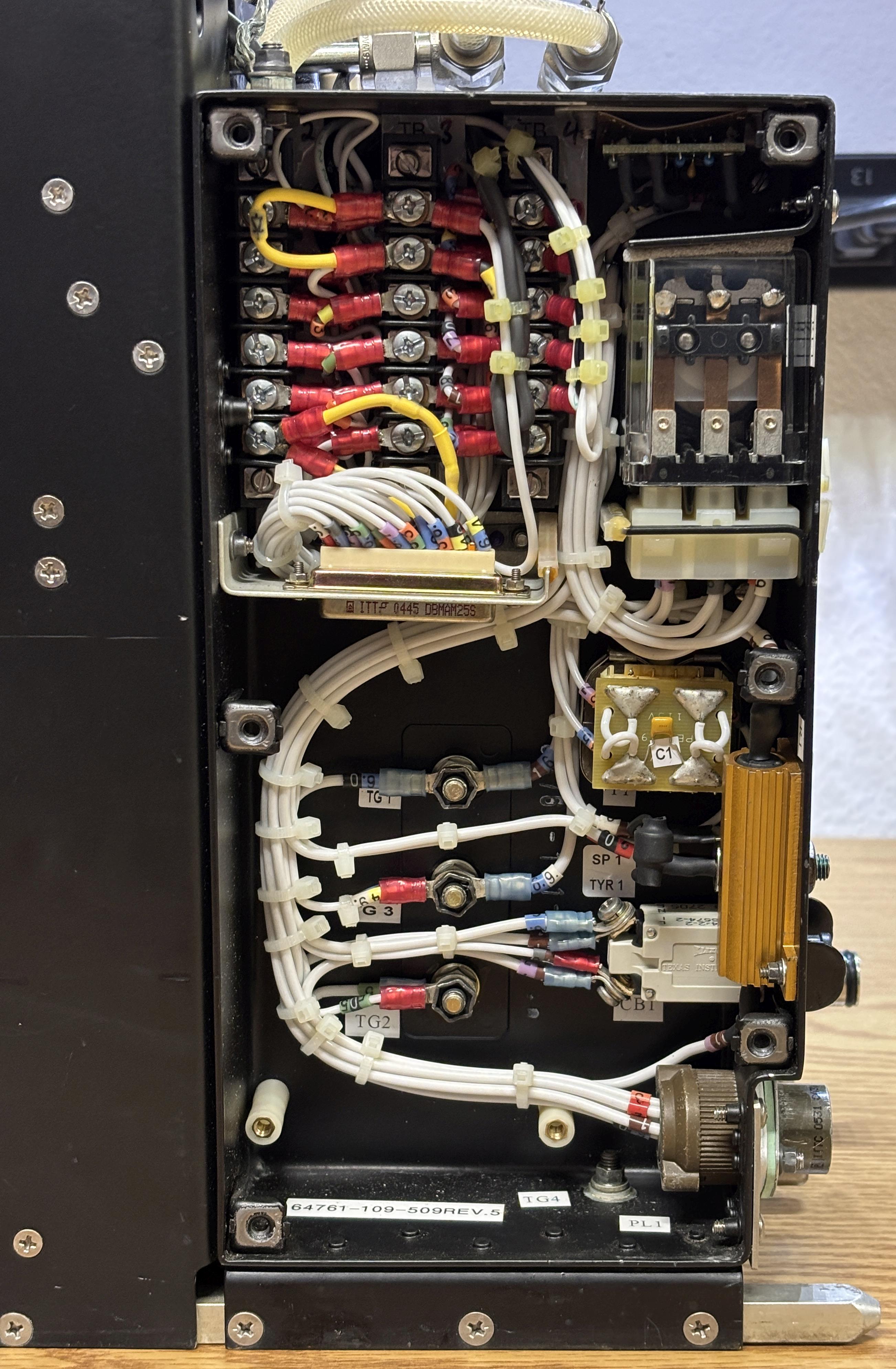
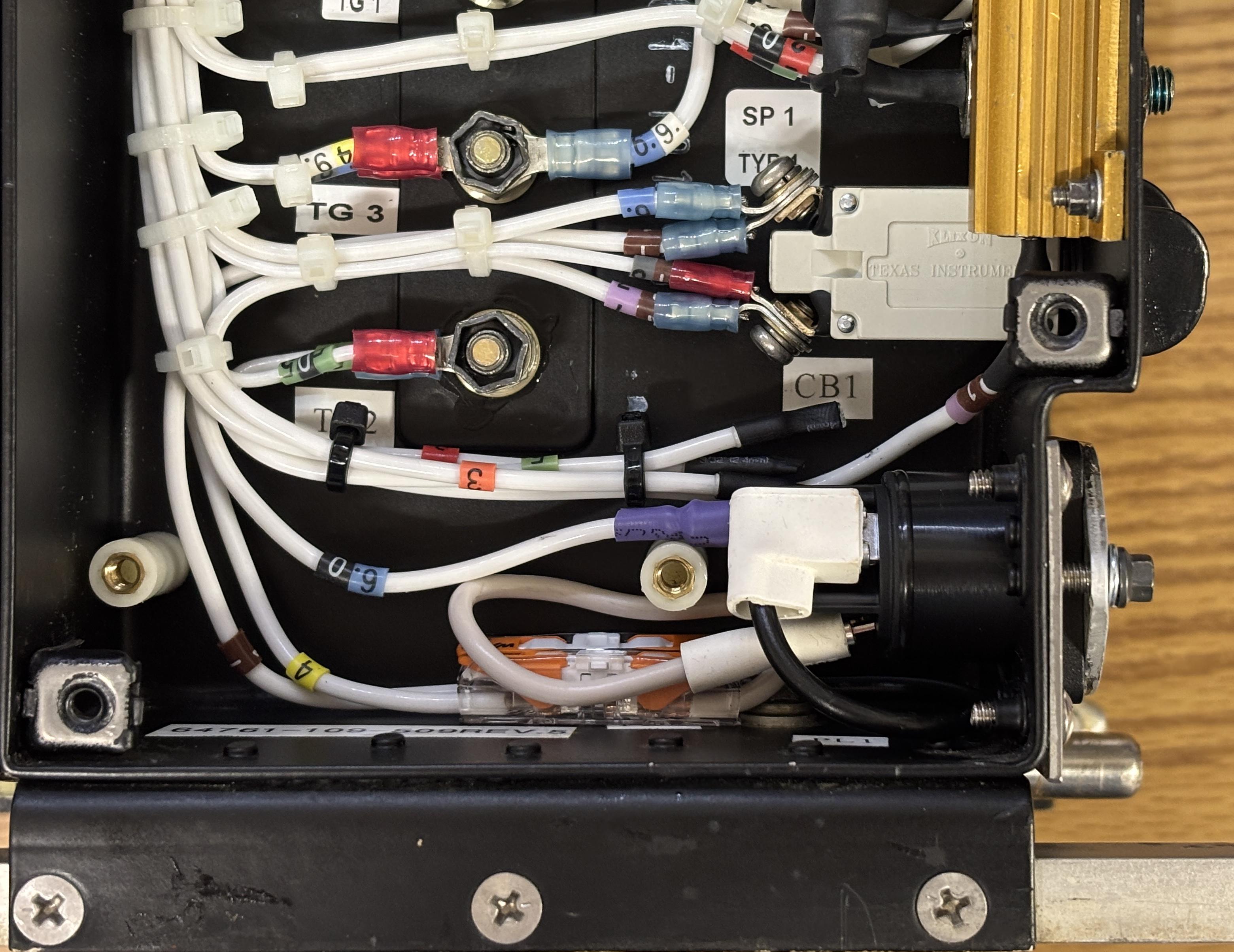
Removing the side access panel reveals a tightly-packed electronics compartment. Located inside are several terminal blocks, the main control board, the heater control relay, the control transformer, and some other components. The sensors, switches, and majority of the wiring lead back to this compartment.

The control board connects via a DB-25 connector and is fastened to standoffs on the other side by some screws. Behind the control board are three grounding studs. These are just chassis grounds and are commoned together along with numerous other ground connections on this unit. The safety and redundancy requirements of aircraft electronics combined with the inherent danger of water and high voltage in close proximity, results in an insane amount of ground connections on this unit.
The majority of the critical components are labeled, each label is provided along with a component description in the table below.
| REF | DESCRIPTION |
|---|---|
| TB1 | Terminal block 1 (outside near tank) |
| TB2 | Terminal block 2 (inside electronics compartment) |
| TB3 | Terminal block 3 (inside electronics compartment) |
| TB4 | Terminal block 4 (inside electronics compartment) |
| TL1-3 | Thermal cutout switches 1-3 |
| E1 | Water tank heating element 1 |
| E2 | Water tank heating element 2 |
| E3 | Water tank heating element 3 |
| E4 | Pot warmer heating element |
| TLP1 | Low water switch (inside tank) |
| MZ1 | Water temperature sensor (inside tank) |
| SV1 | Brew solenoid valve (Peter Paul Electronics 52X00021GH) |
| TG1-TG9 | Electrical grounding studs |
| RL1 | tank heater control relay (Tyco/Potter & Brumfield KUMP-14D18-24) |
| C1 | Capacitor across 24V output of control transformer |
| T1 | Control transformer (AC 115V to 24V 400hz) |
| PCB1 | |
| CB1 | Circuit breaker |
| SP1 | |
| TYR1 | |
| PL1 | Main power connector |
| R1 | Resistor (WH50 series, 5 ohm) |
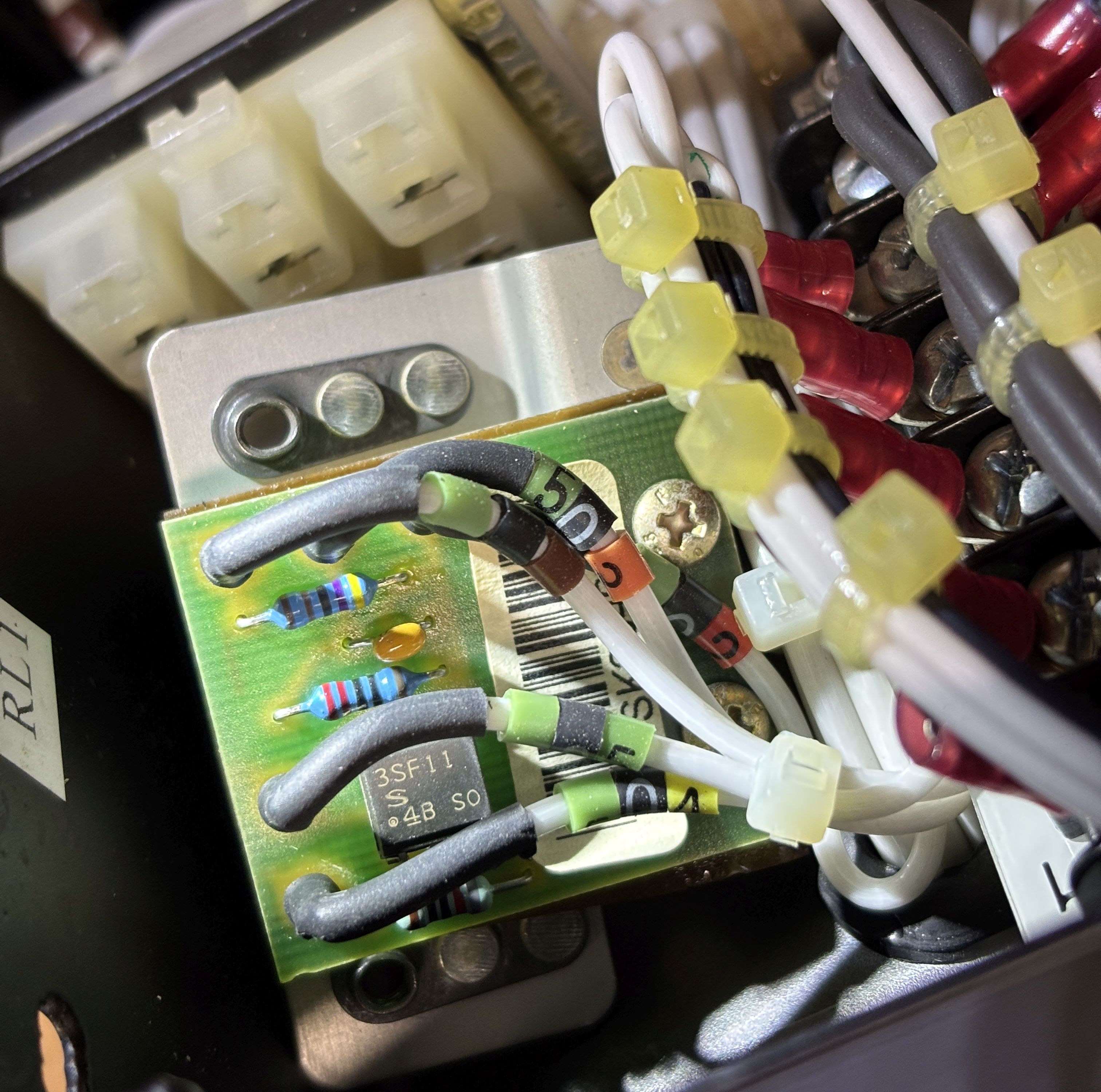
PCB1 is a small standalone board with a single Sharp 3SF11 Phototriac Coupler and some resistors.
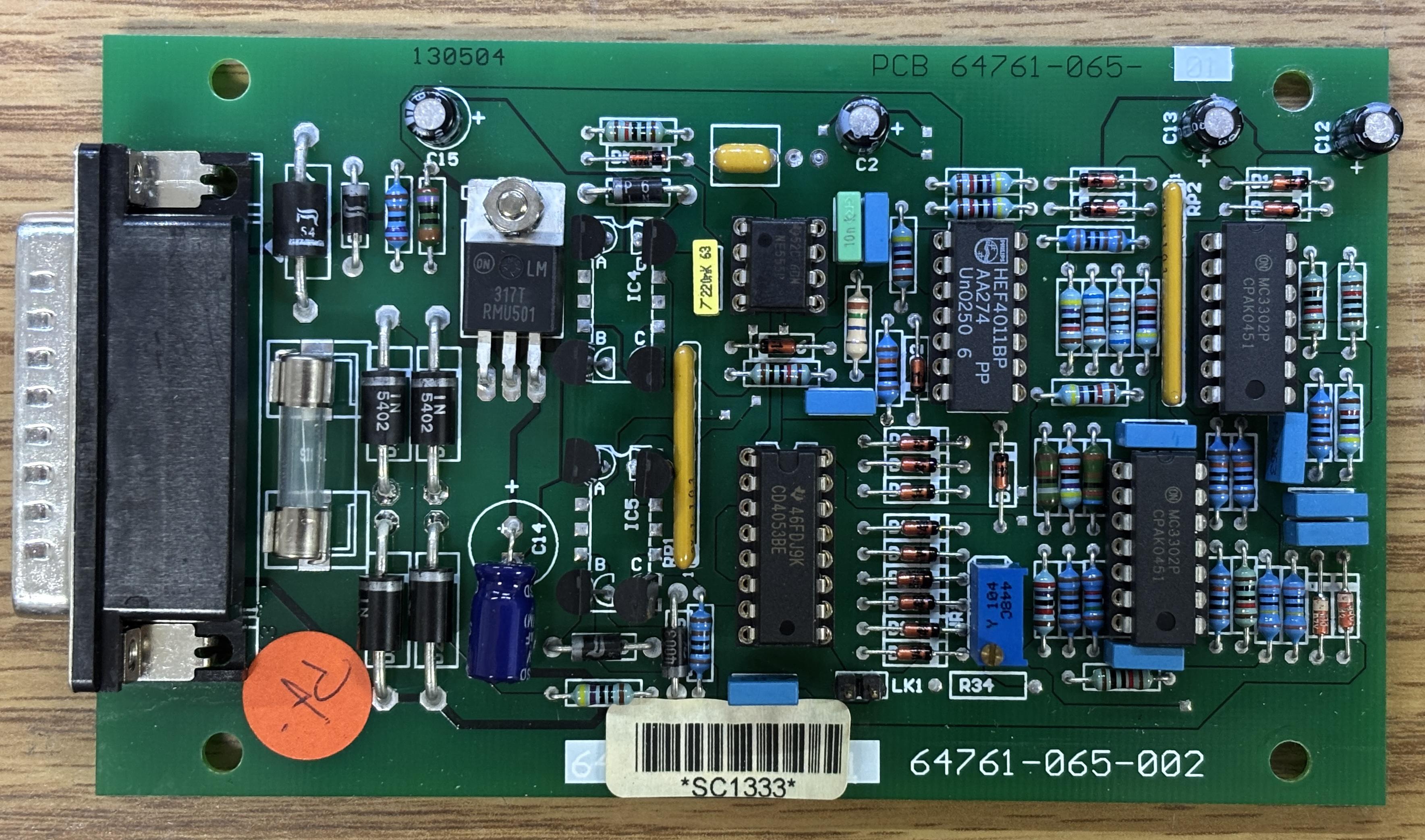
Here is the component side of the main control board. It may look complicated, but the design is quite dated and uses very simple components. The DB-25 connector interfaces with a mating plug on an angled bracket within the electronics compartment. The control board is responsible for monitoring the water temperature, activating the heater relay and brew solenoid, and illuminating the indicator lamps within the switches. It can be powered by around 24V DC and includes a built-in rectifier as the control transformer outputs 30V AC. We are not entirely sure of the purpose of the potentiometer, but it may be used to adjust the temperature setpoint.
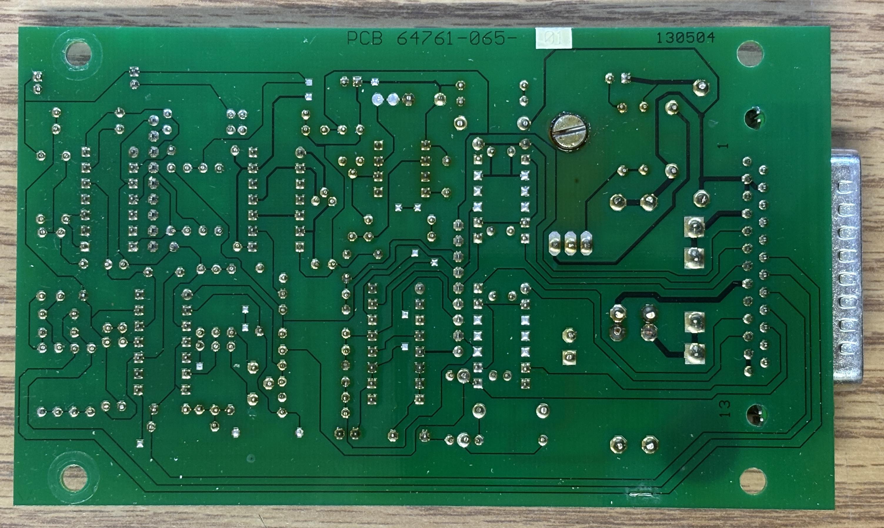
Here is the back of the control board. There is not much to see other than the traces. It appears to be a simple two-layer board. The control logic is very simple as well. It heats the water to a configured setpoint when powered on, as long as the water sensor detects a suitable level in the tank. Once up to temperature, it turns the heating elements off and then will cycle them back on once the temperature drops below the threshold. When the BREW button is pressed, it just activates the solenoid for a precise amount of time needed to fill up the carafe (around 2 minutes). It won't start the brew unless the temperature setpoint is met. The brew function resets after the pot is filled and the heating elements will turn back on to heat the incoming cold water.
Modification for ground use
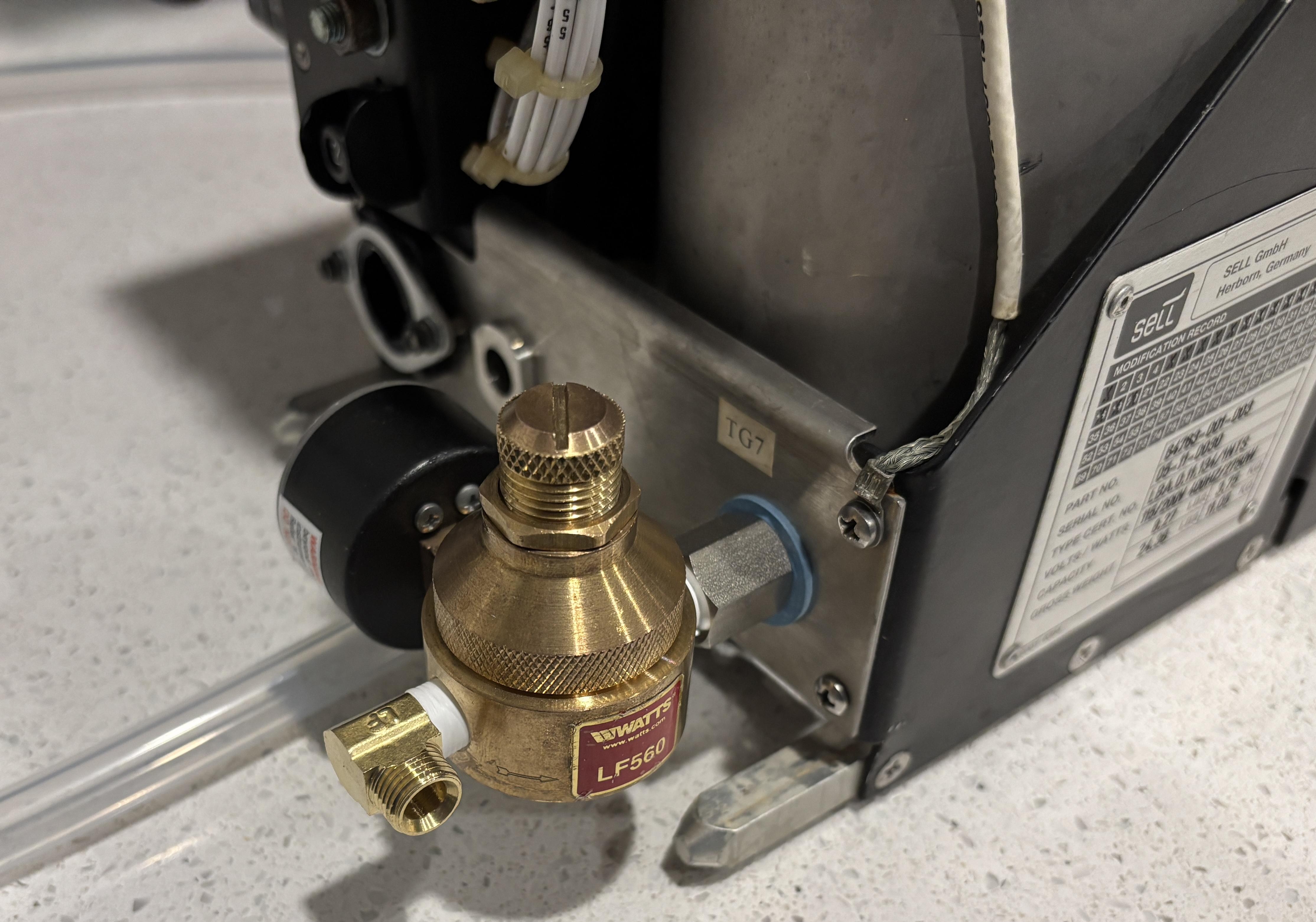
We purchased this coffee maker with the intention of actually using it in the kitchen. While we have quite a bit of electronics experience that includes modifications to avionics, plumbing is new to us. The coffee maker requires a pressurized water inlet, much like a commercial coffee maker. It would have been expensive to source the mating quick-disconnect fitting for the Hansen 2-KL-F connector originally on the machine, so we removed it to reveal a male 7/16-20 UNF threaded fitting. After much trial-and-error and searching, we found a suitable adapter from McMASTER-CARR that converts the obscure 7/16-20 connection to a more common 1/8-inch male NPT. 7/16-20 UNF fittings generally require a crush washer or gasket seal and do not use thread tape. We had a spare automotive crush gasket and used that. We then purchased an additional adapter to convert the 1/8-inch NPT to 1/4-inch OD compression fitting that allowed us to connect the ice maker water line along with an inline shutoff valve to the inlet of the machine. Regular thread tape is fine for the 1/8-inch NPT fitting. We also recommend connecting the drain line (3/8-inch ID) if possible.
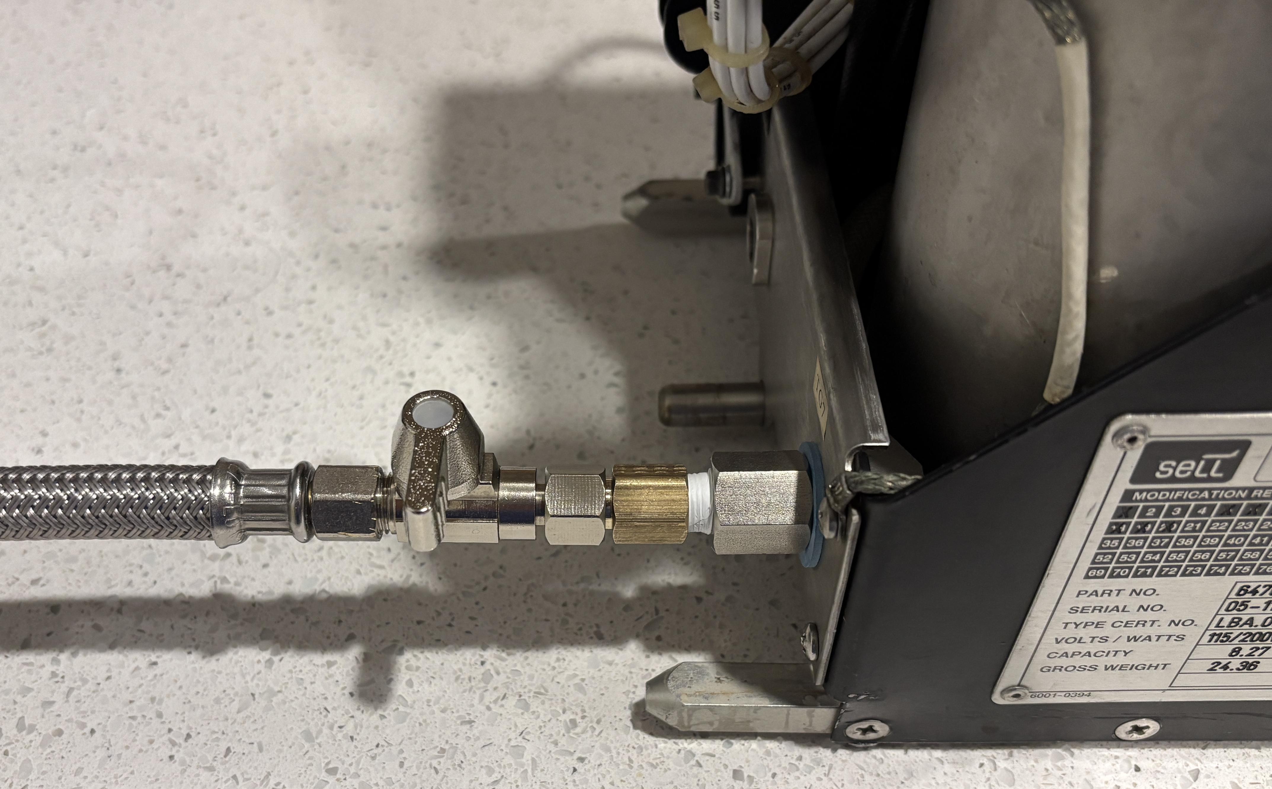
We ran into an unexpected problem when we first connected the water line to the adapted inlet of the coffee maker and opened the valve. Once the tank filled up completely, the top bowed out slightly and a pressure relief/steam valve opened and allowed a steady stream of water to drain onto the bottom plate. Clearly, this system is not designed to handle municipal city water pressure, which is anywhere from 50-70 PSI. Based on the limited information we could find, the water supply pressure in a typical aircraft galley is around 25-35 PSI. This is quite a bit lower and explains the behavior we observed. This problem is not too difficult to solve, it just requires a water pressure regulator. We purchased a WATTS LF560 adjustable pressure regulator. The variant we purchased has female 1/8 NPT connections for the inlet and outlet, and has an adjustable pressure range of 0-125 PSI. It's nice and compact and even came with a pressure gauge, which we used to set the pressure to about 20 PSI. We connected the regulator assembly directly to the 1/8-inch NPT adapter that we previously installed on the coffee machine. We then purchased an additional right-angle 1/8-inch NPT to 1/4-inch OD compression adapter to connect the ice maker line and valve to the regulator.
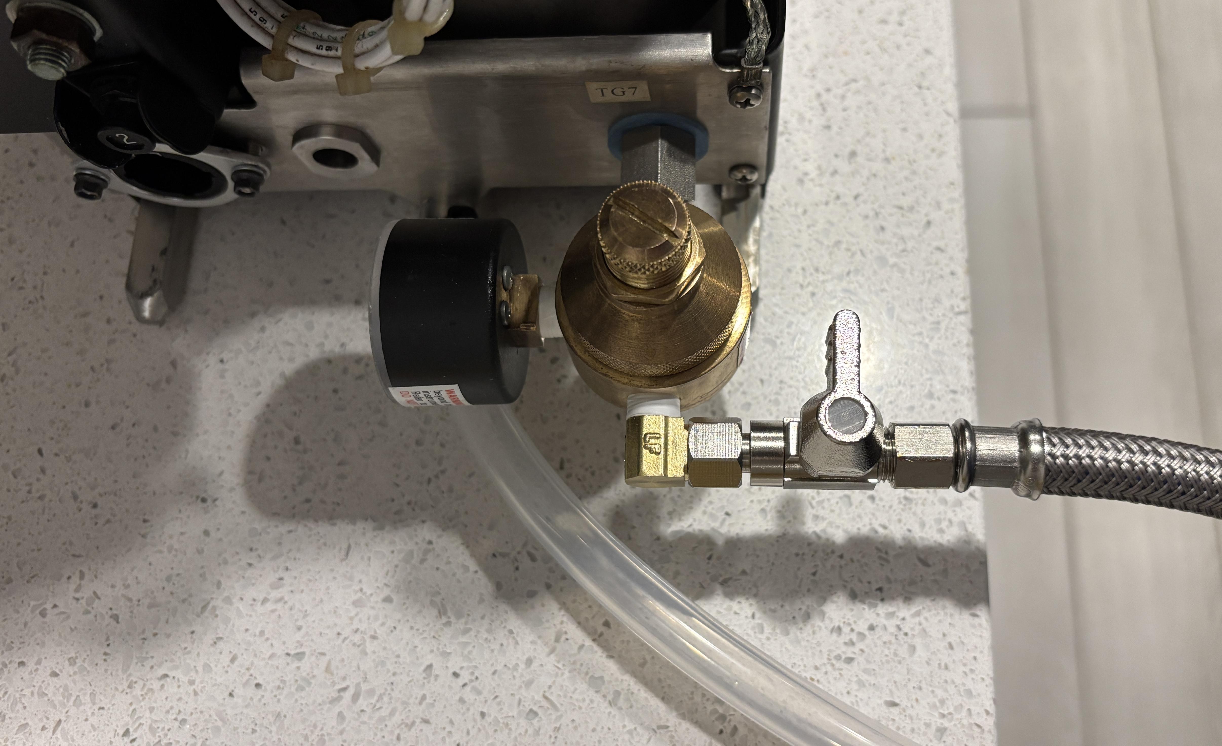
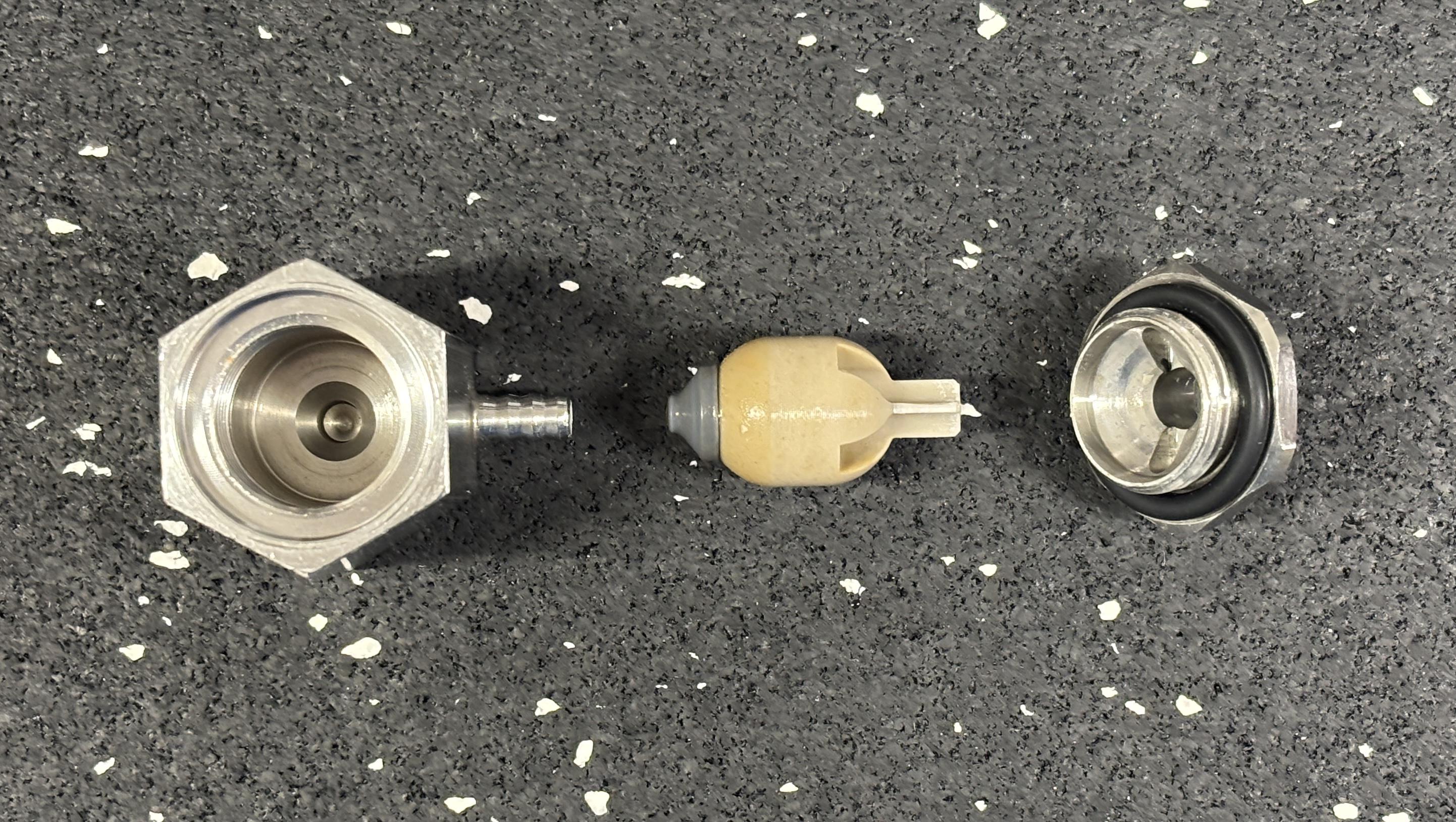
We connected the water inlet and opened to the valve and were pleased to see the pressure regulator working properly. Even when the tank was full, the pressure did not exceed 20 PSI. However, there was still some water leaking from the pressure relief/steam valve. We removed the valve and took it apart to see if it has been damaged by the initial surge of pressure. Luckily, it was not damaged, and just needed to be cleaned. Some sediment has gotten in the valve and was preventing it from sealing completely. This seems to be more of a steam relief valve as it uses a small plastic float and gasket which seals the opening on the top when water pushes the float up. It seems like the presence of steam would cause the float to fall back down and allow the steam to escape, while preventing water from flowing out. There is a dedicated pressure relief valve also on the top of the water tank which is likely the main over-pressure safety device. Cleaning and re-installing this valve solved the leaking problem and now the tank fills as expected with no issues!
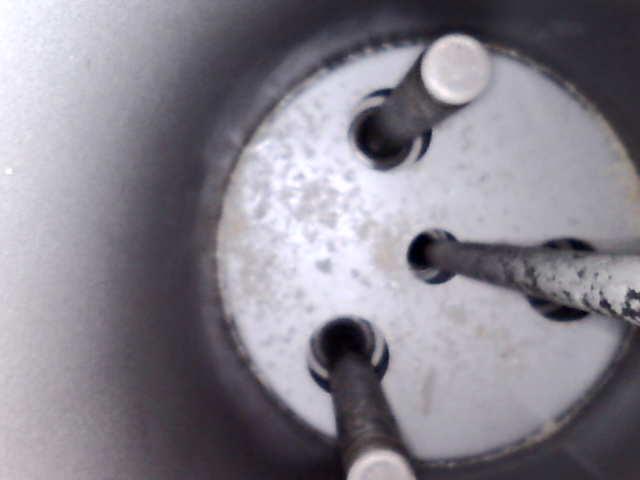
While the steam valve was removed, we figured it would be a good chance to get a peek inside the water tank with a scope camera. Not much to see than the three heating elements and some inlet/outlet openings.
Since the coffee maker expects 115V 3-phase AC power at 400Hz, it needs some modifications to work from a standard 115VAC 60Hz wall socket. Luckily, Michel from Le Labo De Michel has already worked on converting a very similar aircraft coffee machine. He even provided a schematic with the recommended modifications for ground use. The coffee maker Michel worked on is not the same brand as ours, but since they all follow the standard, the components and design are essentially the same. First, we removed the aircraft electrical connector on the back and replaced it with a Neutrik powerCON TRUE1 connector. These are capable of carrying up to 20 amps, are extremely reliable, and are even safe to disconnect under load.
Since the heating elements are just simple resistive devices already intended for use with 115V AC, no complex modifications are needed. Following Michel's diagram, we connected the AC live terminal to phase A, neutral to the original neutral, and ground to PE (protective earth). The reason for choosing phase A is that the pot warmer and control transformer are fed from phase A. Phases B and C are exclusively used for the other two heating elements. Since 3-phase power is not available, and connecting all elements would use a huge amount of power, we just connected the first heating element. Each element draws around 850 watts. Therefore, our coffee maker will have 850 watts of heater power. The only downside of this is a longer wait before the water is heated to the target temperature. It is possible to connect another element for around 1700 watts of total heater power, but that's a bit much for our use case. Michel also included instructions for 230V, which involves further modifications. Luckily for us in the US, we use 115/120V which makes this modification easier. There is little room near the powerCON connector once the control board is installed so we had to use a combination of normal and right-angle spade lug connectors. We used WAGO connectors for the live and neutral but left the ground wired directly to the spade lug.
Since this system was intended for use with 400Hz AC, the small control transformer would be destroyed if it was operated on 60Hz. This control transformer must be disconnected and replaced with an alternative capable of 60Hz operation. We de-soldered the wires from the transformer terminals but left it in place, and added some extensions to the wires. We opted to use a small switching power supply from MEAN-WELL that accepts 115VAC in and outputs 24V DC. We drilled a hole in the side panel that covers the electronics compartment and mounted the IRM-20-24 power supply board within a plastic box to the side cover. There is very little free space within the coffee machine, so this was the easiest way. We used a DEUTSCH connector on the inside for the power supply connections to allow for easy removal of the side cover.

We added a small piece of foam to keep the power supply module from moving around in the box once the cover is installed.

During testing, we needed to override the low water switch by grounding the exposed contact of TLP1. This allowed the heater relay to engage when the water tank was empty. Don't let the heater run with an empty tank for more than a few seconds as this could burn up the heating element. When testing, we also learned that the brew handle must be in the locked (downwards) position for the pot warmer heating element to engage. With the power supply installed, all electrical functions are now working on 115 VAC 60Hz! Below is an image of the front panel controls with the lamp test button being held down, which illuminates the buttons.
No coffee maker is complete without a carafe! Ours did not come with one, so we had to buy it separately online. It was surprisingly hard to find any information about the dimensions of an aircraft carafe, but luckily we came across a used one that fit perfectly.
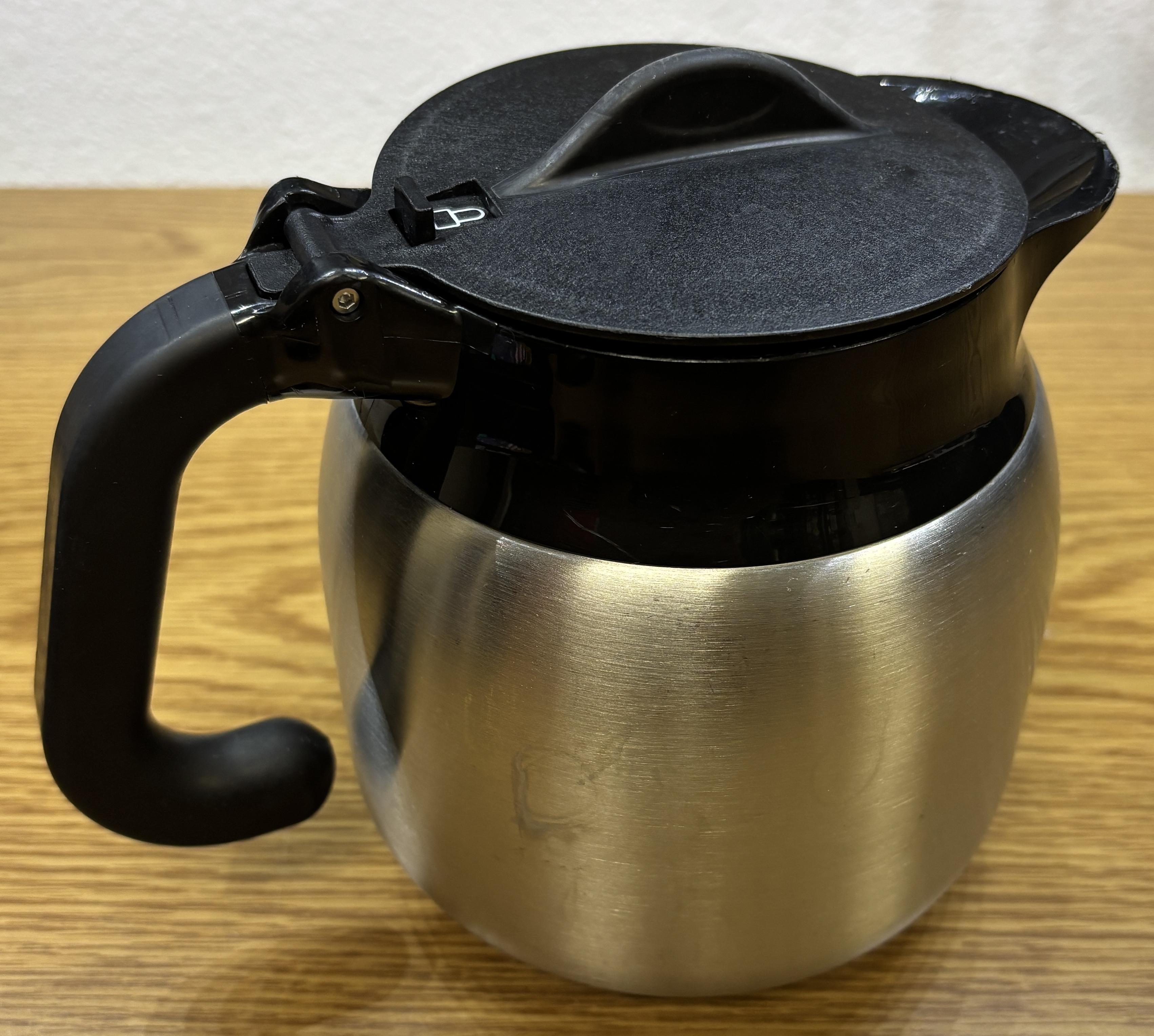
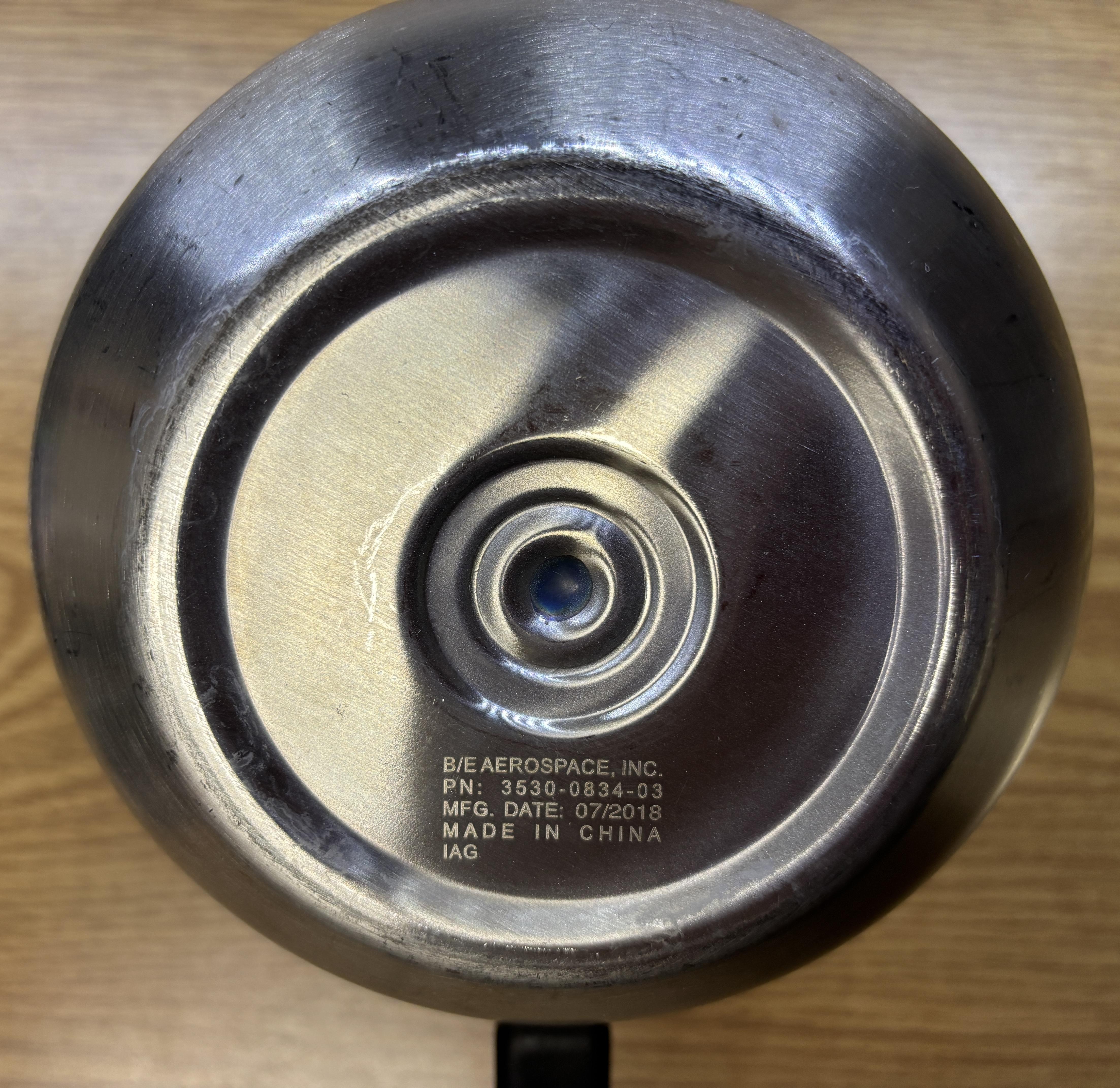
The one we bought was manufactured by B/E Aerospace in 2018 and is in good condition. We just had to run it through the dishwasher to clean it up.
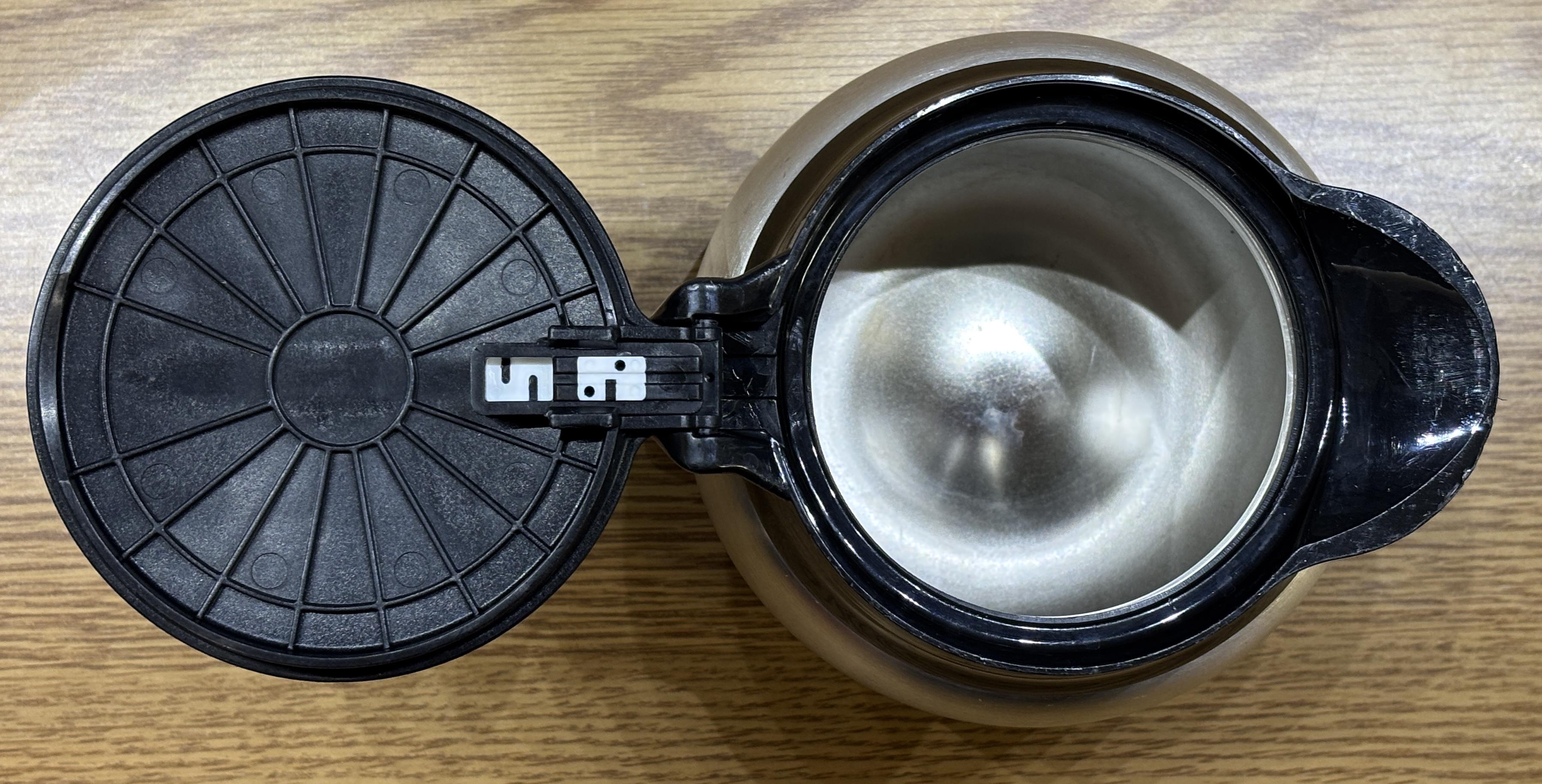
It is quite durable and has a locking lid to prevent spills that we later removed since it's not necessary for our application.
This was quite an involved project, testing our electronics knowledge and requiring us to learn about water pressure and various plumbing fittings. In the end, it was a success and we now have a functional aircraft coffee maker in the kitchen! With only one heating element connected, it takes about 7 minutes to heat cold tap water up to the setpoint. Brewing takes about 2 minutes, and the coffee produced is extremely hot! As far as the taste, it's about what you'd expect for aircraft coffee.
Visit the links below to learn more about the process of converting the coffee machine for ground use. Also check out the "Essence Galley Inserts Collection" from Collins Aerospace to see some modern galley appliances.