This is an undercarriage control lever or landing gear control lever from an unknown aircraft. It was purchased online as a parts unit for use in a simulator project. The role is straightforward, this lever electronically controls the aircraft's landing gear lever to either extend or retract it.
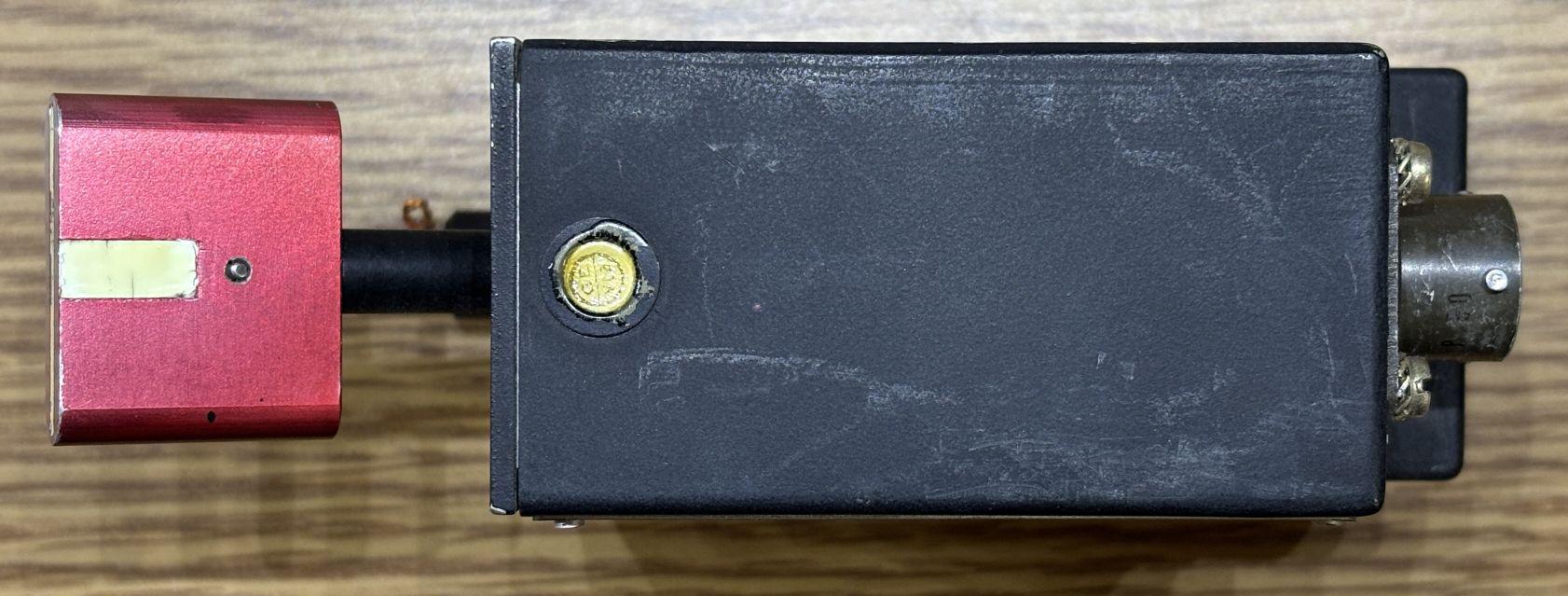
The assembly is typically mounted behind a cockpit panel and secured by screws from the front. All lettering and symbols would be on the panel and not this unit. There was a small piece of safety wire placed through the hole of the manual override button. We later removed this piece of wire as it was not needed. On the top of the unit is a single slotted screw which secures the outer casing to the inner frame.
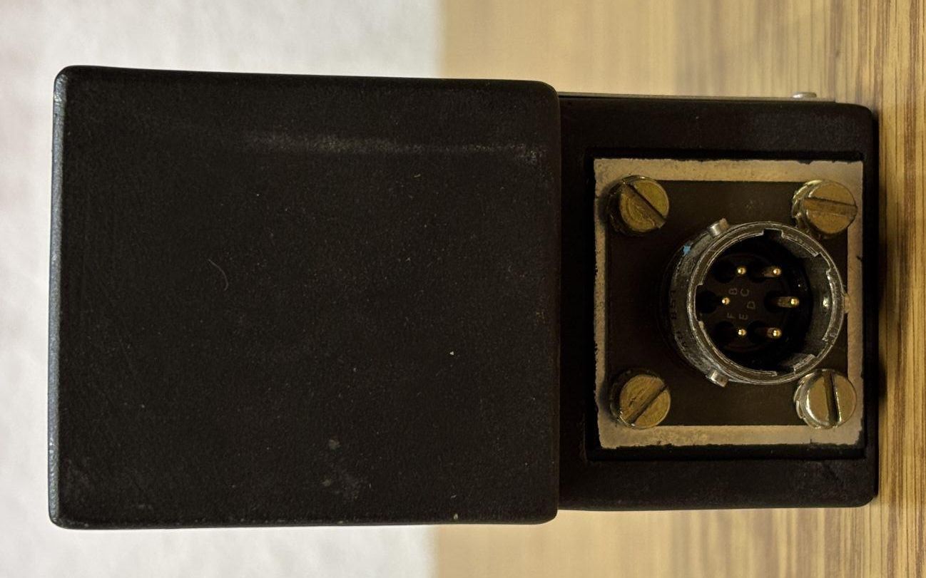
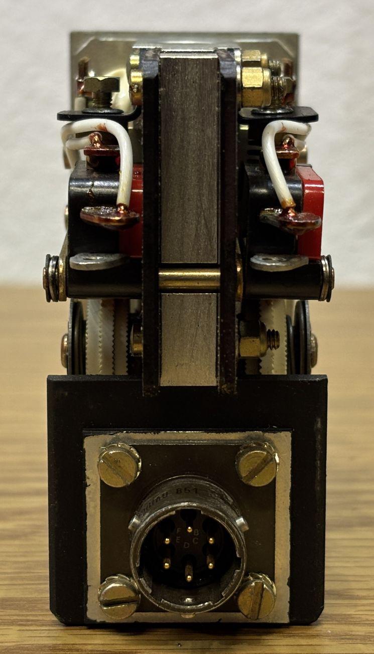
On the back is a single 6-pin twist-lock connector that is recessed into the bottom section of the case. The edge of the connector is nearly flush with the surface of the above casing section. The connector is secured to the inner frame by four slotted screws and lock washers.
On the bottom is a single slotted screw that was recessed into the case along with an anti-tamper seal. We removed this seal and the small collet, which resulted in damage to the collet. We later replaced it with a plastic collet since this component will not be used in an aircraft.
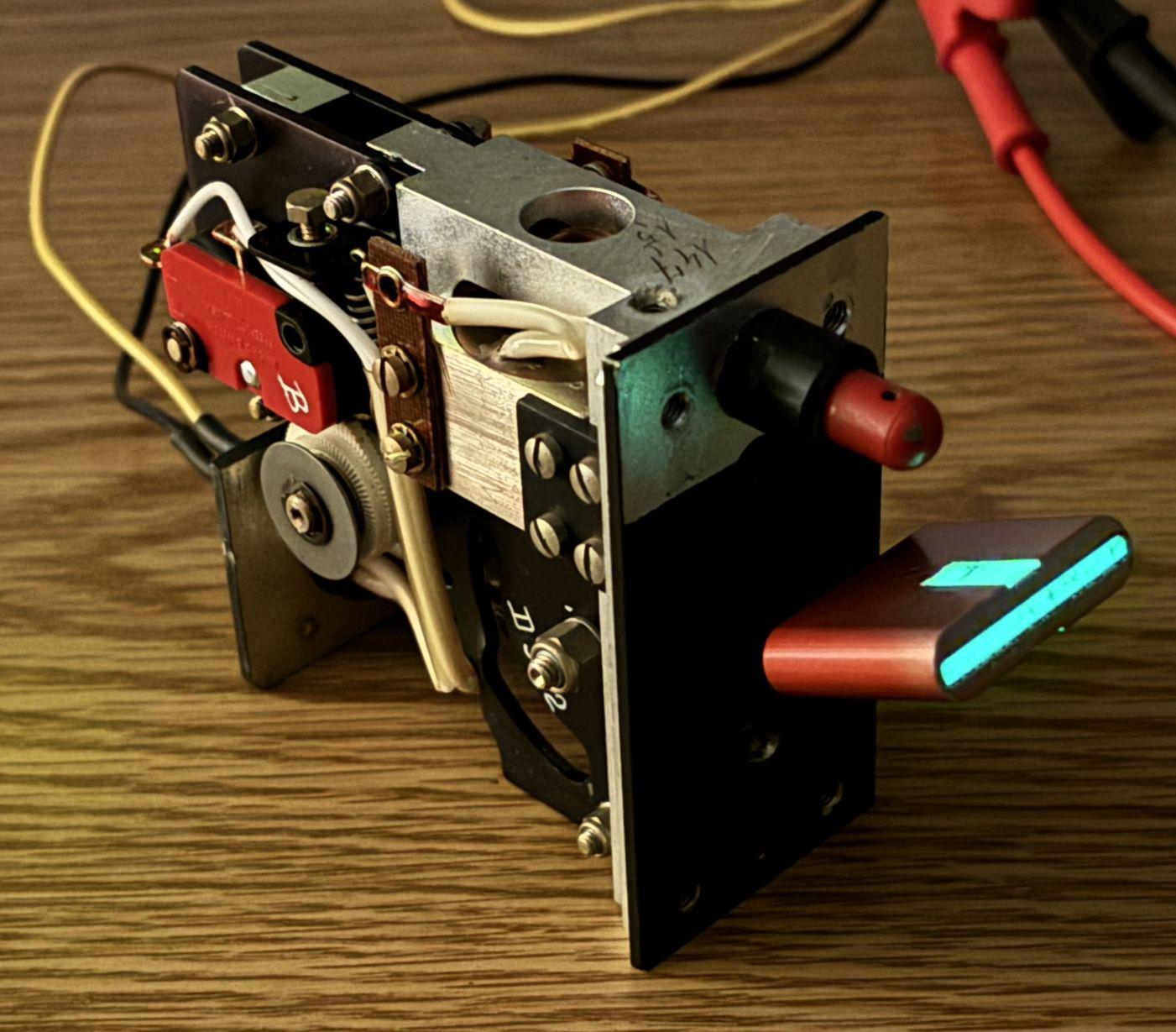
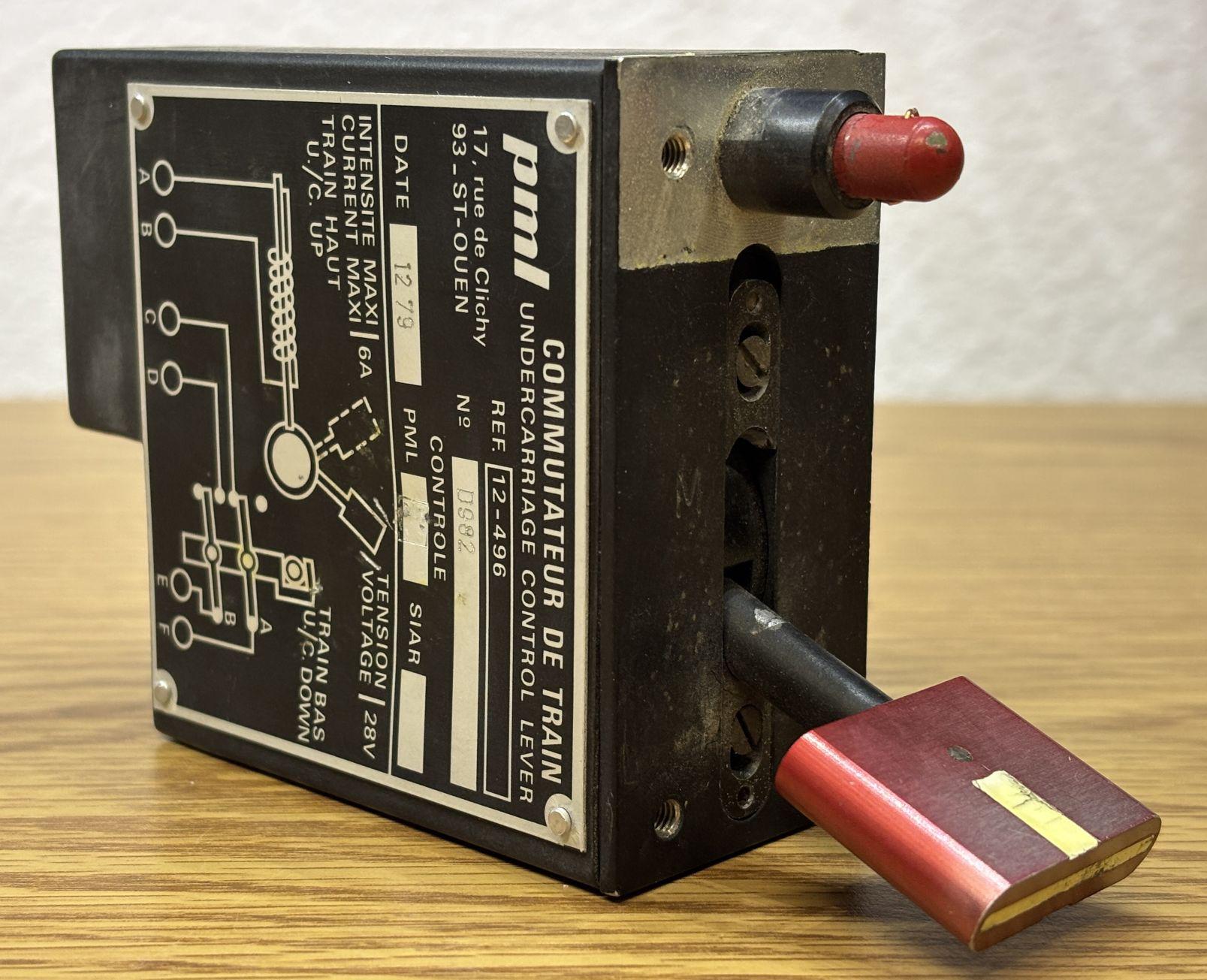
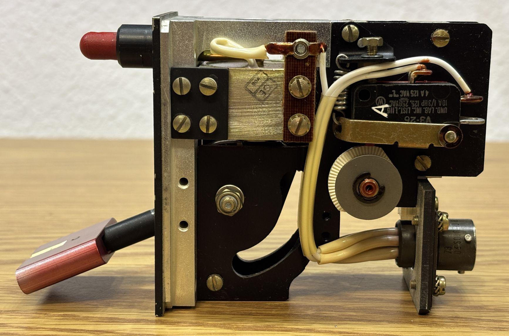
Removing the two slotted screws on the top and bottom allow the metal casing to slide away from the inner frame, revealing the switch and solenoid components as well as the wiring. This landing gear lever uses a spring-loaded mechanism to create a very positive action when the lever is thrown up or down. This ensures switch contacts are made firmly and reliability (minimal bounce) and also assures the pilot that the lever has been actuated successfully. Conveniently, the pinout, wiring diagram, and operating voltage is listed on the plate riveted to the side of the casing.
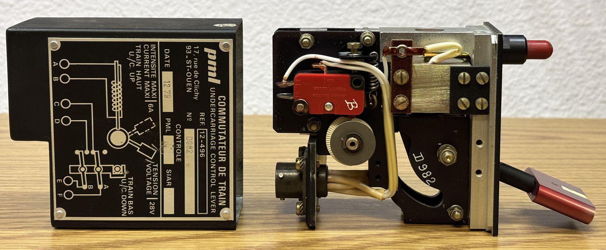
The gear selector lever is connected to a mechanism that actuates two plastic cams that either depress or release a microswitch on either side of the frame. The switches are configured in an opposing NO/NC configuration, which means one switch will be open while the other is closed. When the gear lever position is changed, the switch states are reversed. There is a magnetic solenoid that when powered, allows the control handle to be moved to the upwards position (retract landing gear). In the event of an electrical or solenoid failure, the red button manually releases the locking pin when pressed, which allows the handle to be moved upwards. The control handle can always be moved downwards (extend landing gear) regardless of the solenoid or override button state.
In the image below, you can see the two microswitches, plastic cams, and the connector. Each switch is wired directly to the rear connector, independent of the other.
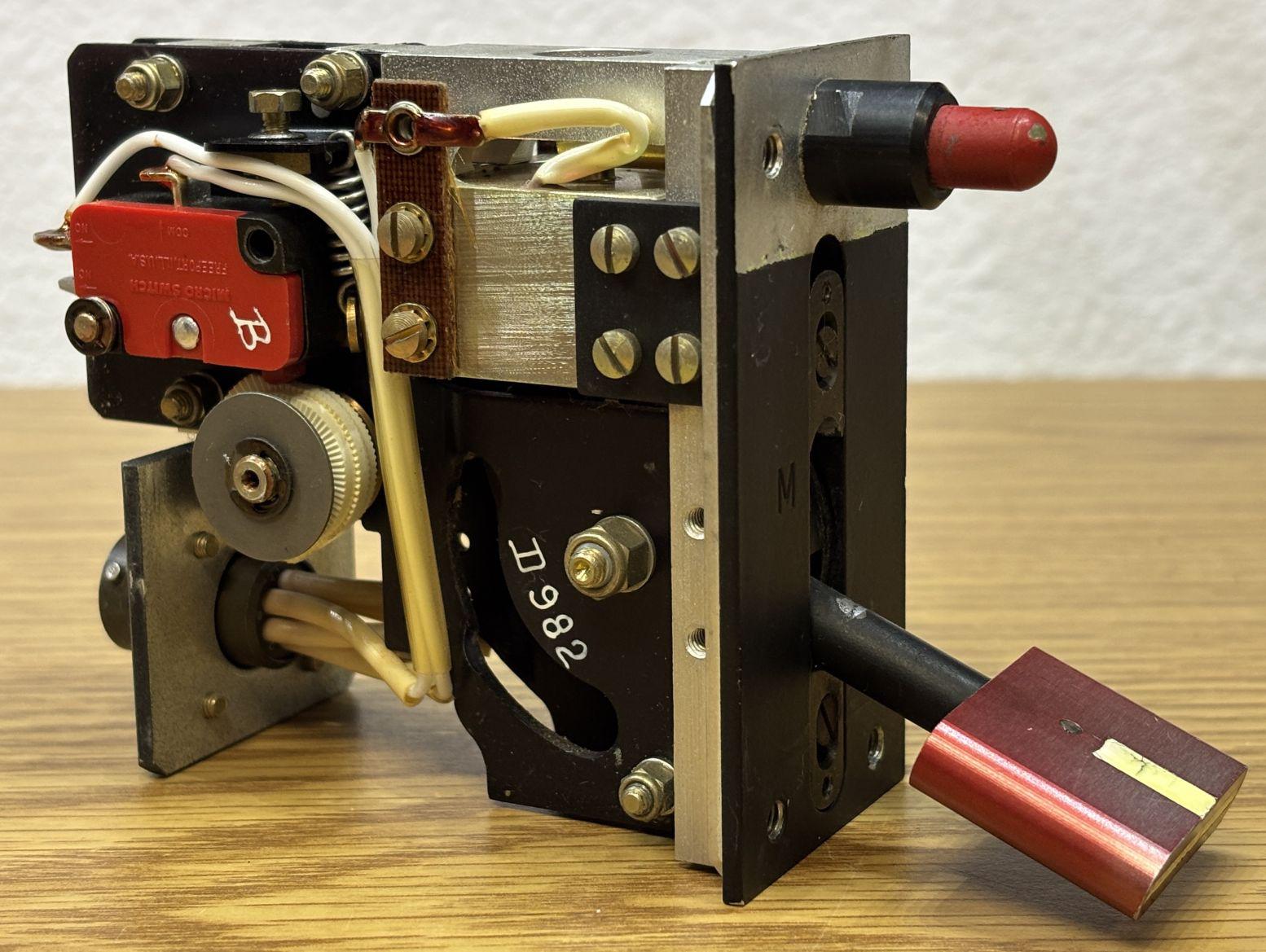
Here is the other side of the assembly, which is essentially a mirror image of the first side. It's worth noting that the switches are secured to the frame via a spring-tensioned mount that has an adjustment screw on the top. This allows for a small amount of movement of the switch as the cams actuate, which likely prevents damage from the pressure of actuation.
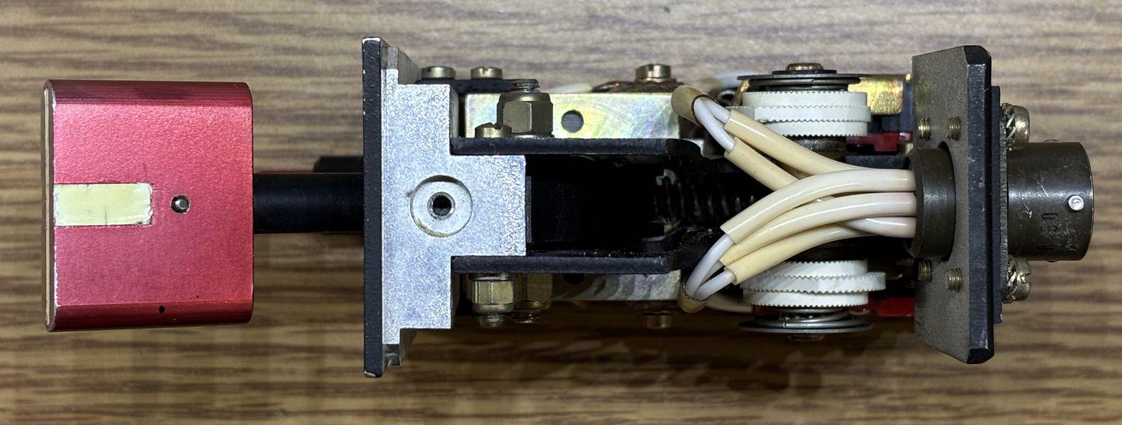
From the bottom, we can get another view of the plastic cams. It looks like they can be adjusted as evident by the stacked arrangement with interlocking teeth. Presumably they can be adjusted if the switch was replaced or even reconfigured to change which gear lever state depresses the switch.
As expected, applying 28V DC power to the solenoid pins caused it to click and unlock the lever, allowing it to be moved upward without pressing the override button. The painted section of the aluminum control handle glows in the dark (faintly) when first charged with a bright flashlight. Do note that there is no electronic illumination.