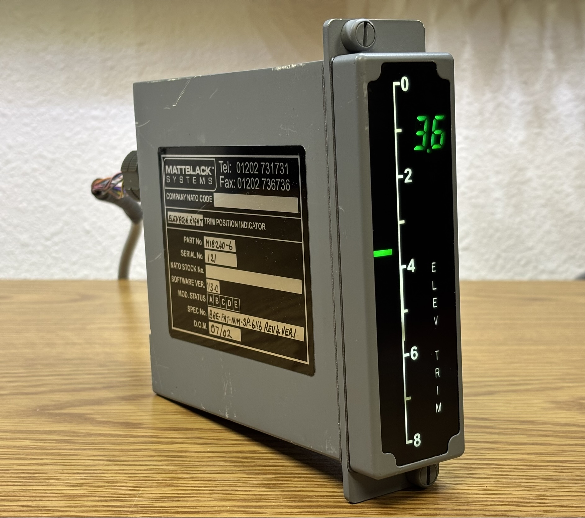
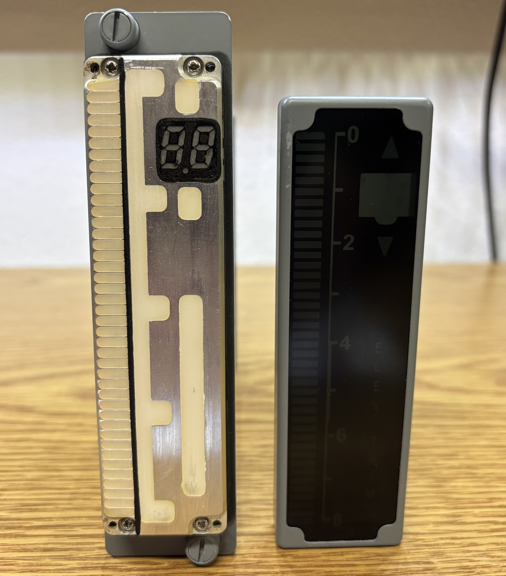
The MIB240-6 is a digital indicator module for the elevator trim of a Royal Air Force aircraft, likely the Nimrod based on some markings on the board. The indicator mounts in the cockpit rack system much like many other commercial and military avionics modules. It's fully digital, communicates over RS-485, and is powered by the 28V DC bus of the aircraft. The indicator displays the elevator trim position using a numerical readout and a vertical bar graph.
A shroud slides over the inner frame and components. On one side of the shroud is an information label, and on the other side is a FWD indicator with an arrow that shows the proper mounting position.
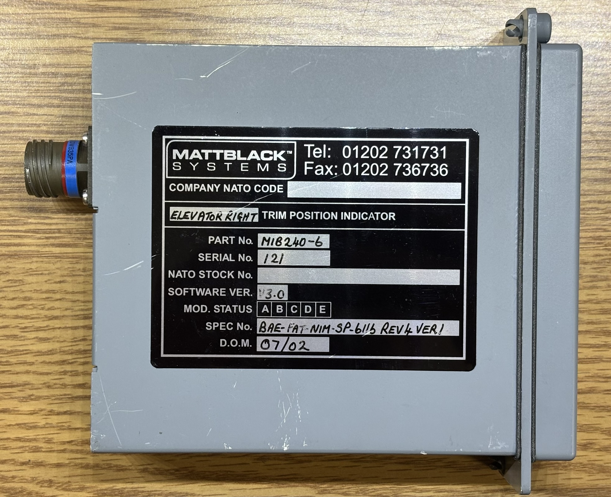
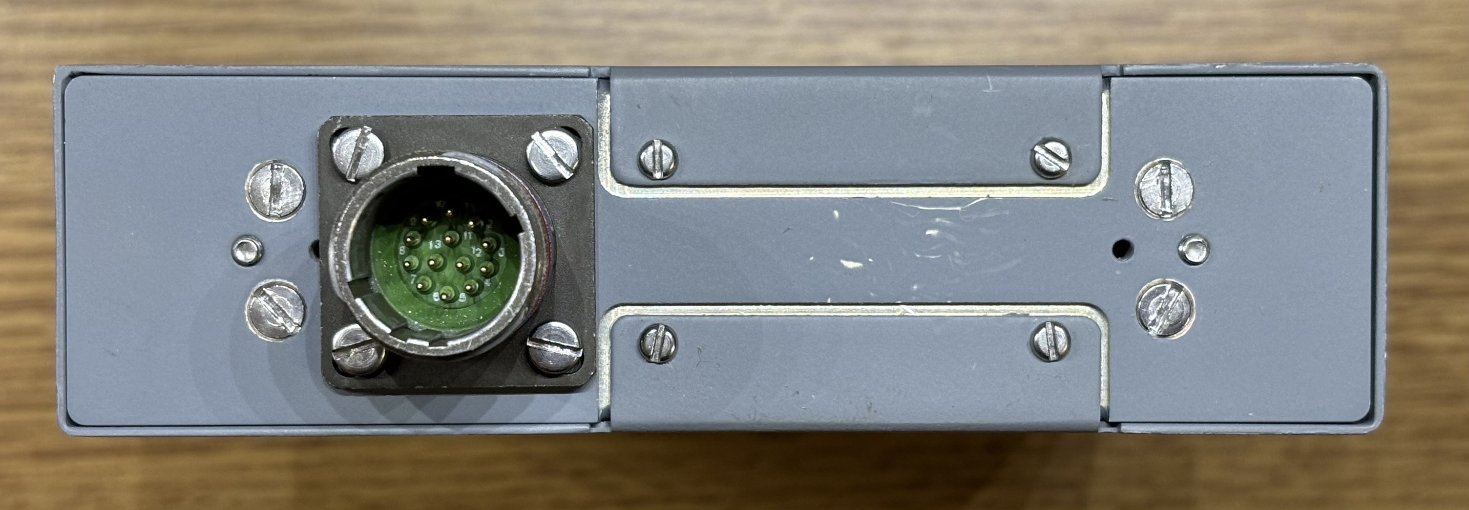
The only notable component on the back of the unit is a 13-pin Souriau twist-lock connector. Removing four slotted screws on the back allows the shroud to be slid off towards the back.
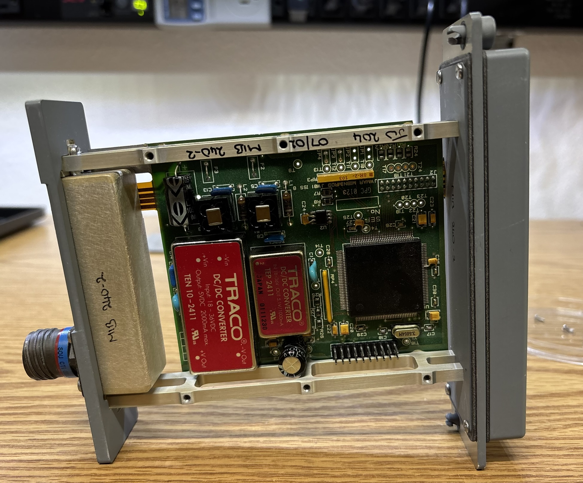
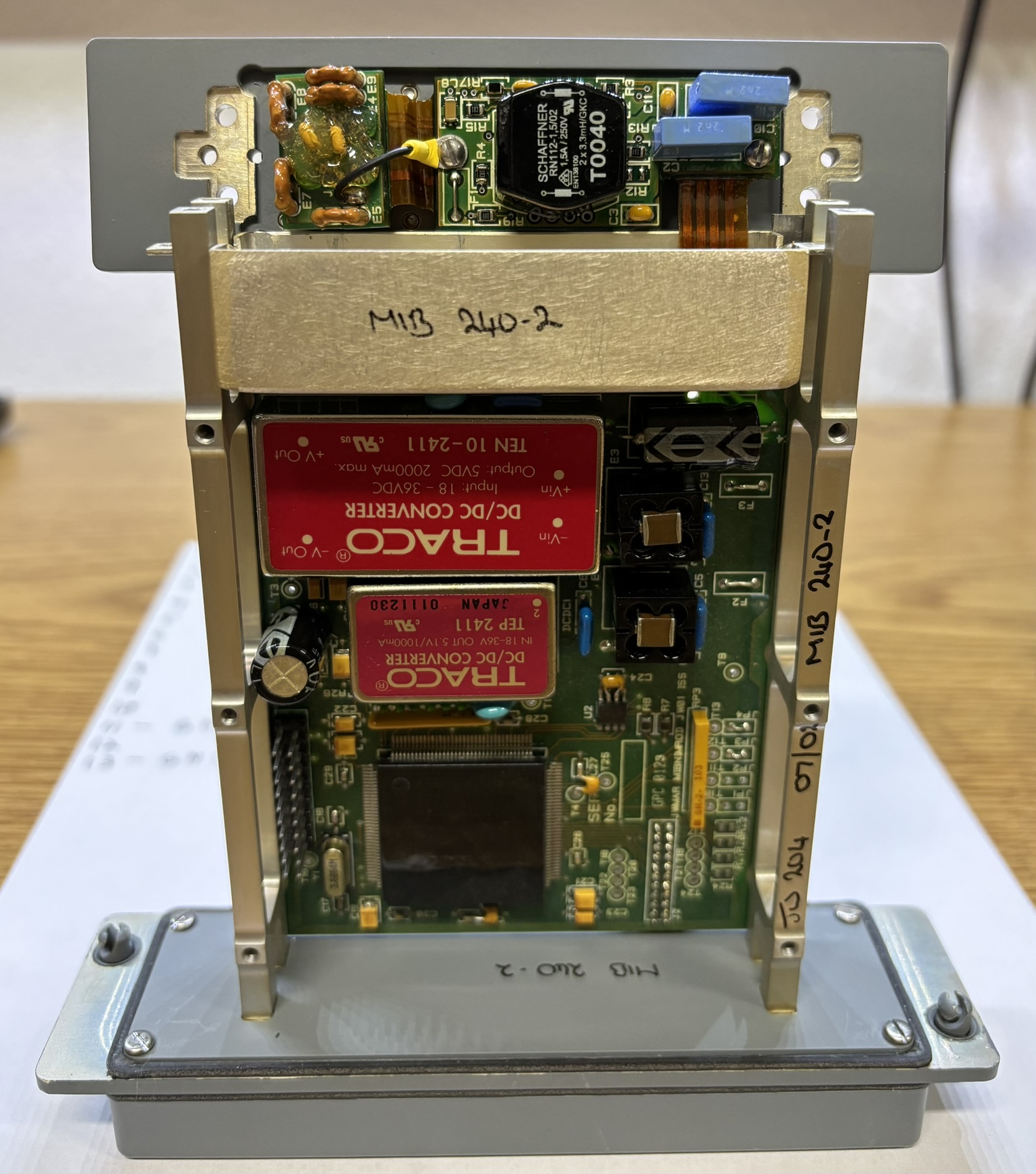
With the shroud removed we can see a single circuit board mounted to a milled aluminum frame. There are 2 TRACO DC-DC converters, a capacitor, and some filtering circuitry. The large IC is a ST10F167 16-bit MCU. Located adjacent to the MCU is a MAX1487 RS-485 transceiver. Lastly, there are some unused pin headers, likely for diagnostics and programming.
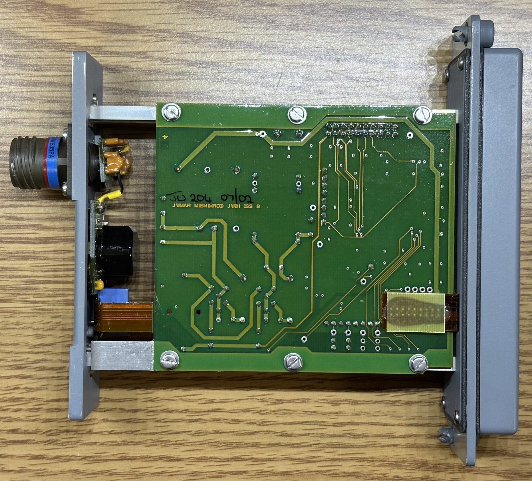
This is the back of the circuit board. There aren't any significant components here other than a soldered-on flat-flex ribbon cable for the front display. However, the silkscreen text leads us to believe that this device was a component from an RAF Nimrod.
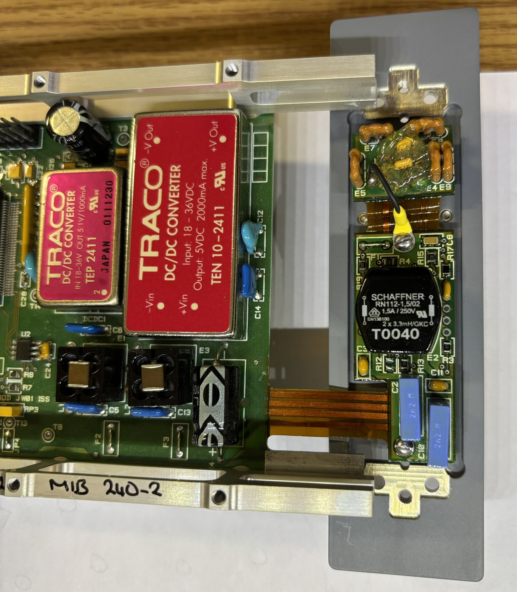
The metal box mounted to the back panel conceals couple of circuit boards that are used to break out the connections from the plug on the back and provide power/signal filtering.
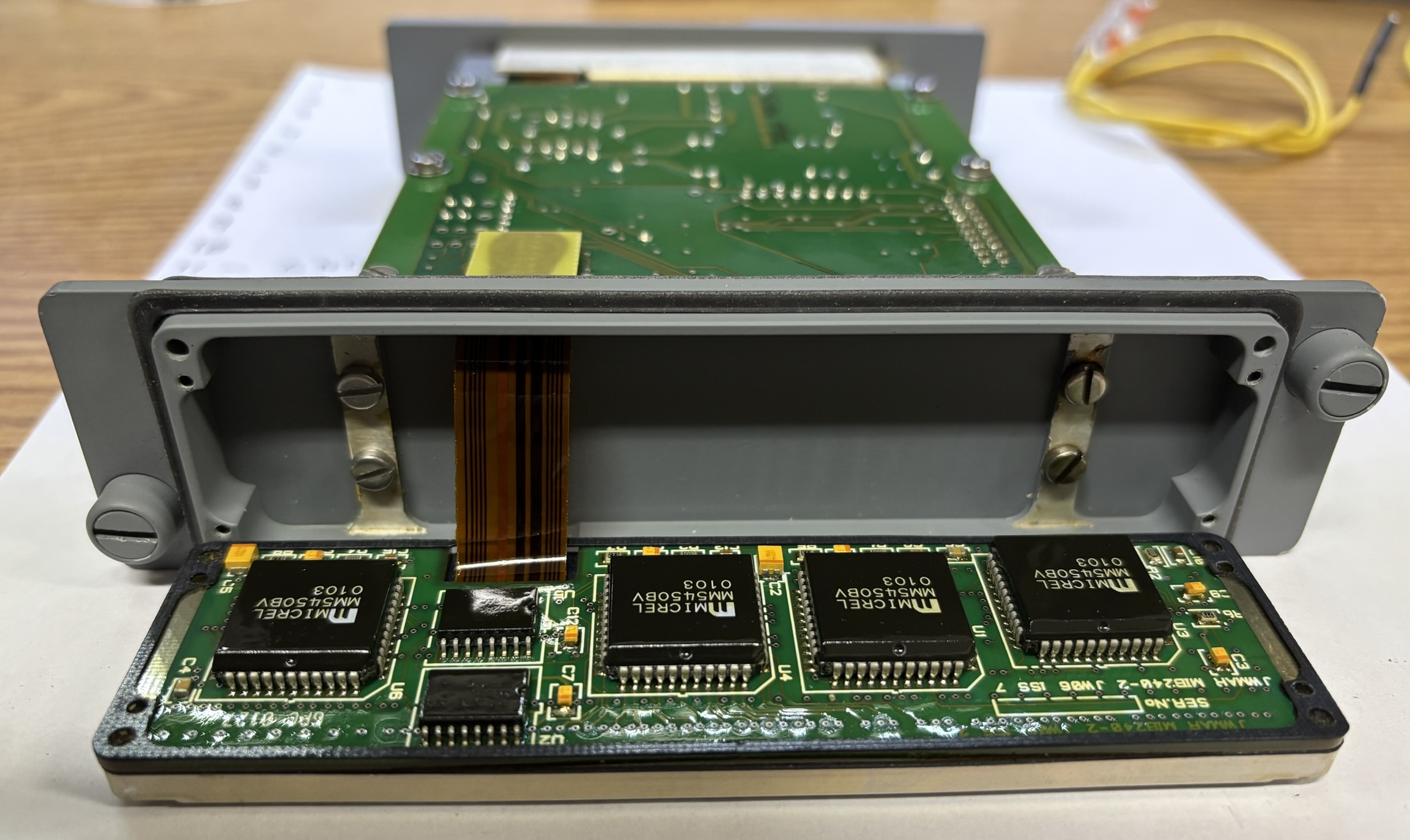
All boards in this unit are connected via flat-flex PCB links and it appears that they were all manufactured as one. This makes tracing connections very difficult and also inhibits disassembly due to the delicate nature of the flat-flex.
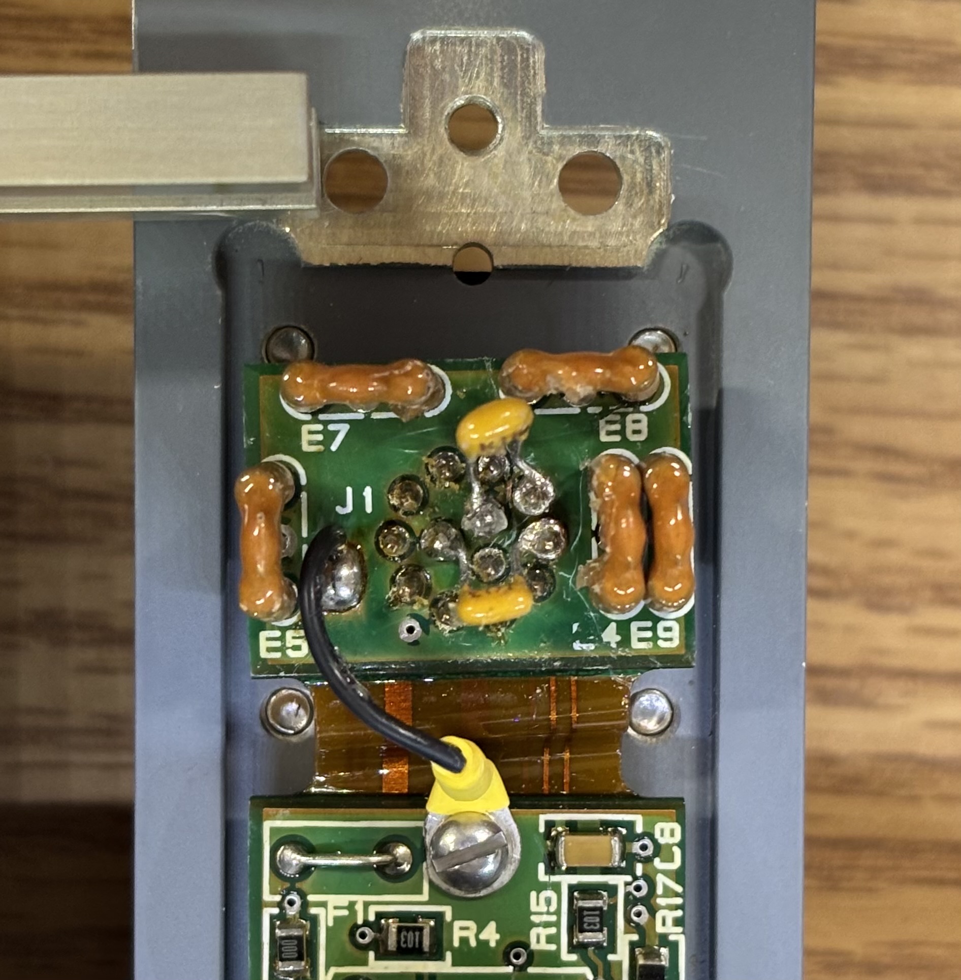
We scraped out all the melted glue from the pins of the rear connector breakout board. This board is soldered on the pins of the twist-lock connector and passes the connections over a flat-flex to the adjacent board. The two yellow capacitors each go between an RS-485 channel and a ground pin. There is also a dedicated ground connection in addition to the flat-flex.
The front cover can be removed by unscrewing 4 slotted screws on the reverse side. The cover is comprised of a metal frame with a dark translucent plastic stencil. When the indicator is illuminated, it can be seen clearly, but looks like a blank screen when off. Behind the cover is a custom illuminated plastic module with various sections that are individually controlled. These sections include a bar graph, dual-digit seven segment display, and static sections for the scale and text.
Removing the 4 Phillips screws allows the illuminated plastic module to hinge away from the remainder of the frame. There is a small PCB mounted to the back of the plastic module. On it are 4 MICREL MM5450 LED display driver chips. Therefore, we are assuming that LEDs are used to illuminate the display segments.
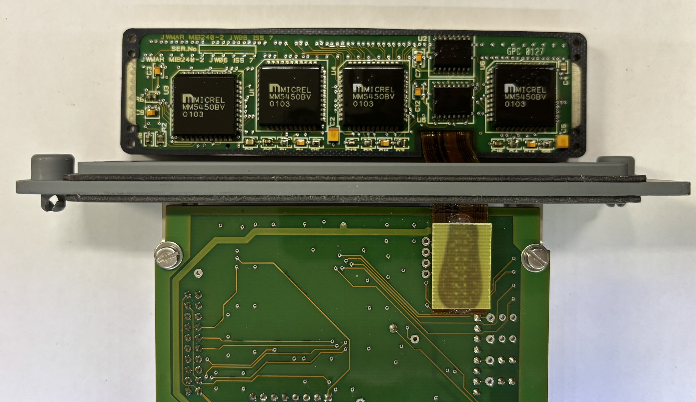
This module is connected to the main circuit board via a flat-flex ribbon as well.
Here is a partial pin-out for the indicator. We deciphered the pin-out using basic continuity testing and trial-and-error, but there are some pins that we are still unsure of. The flat-flex ribbons along with a thick layer of conformal coating make it very hard to probe and trace connections.
| PIN | DESCRIPTION |
|---|---|
| 1 | POWER INPUT (28V DC) |
| 2 | |
| 3 | |
| 4 | |
| 5 | |
| 6 | RS-485 A |
| 7 | RS-485 B |
| 8 | |
| 9 | |
| 10 | |
| 11 | GROUND |
| 12 | LAMP TEST (GROUND TO ACTIVATE) |
| 13 | GROUND |
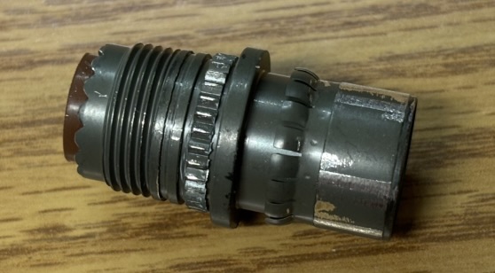
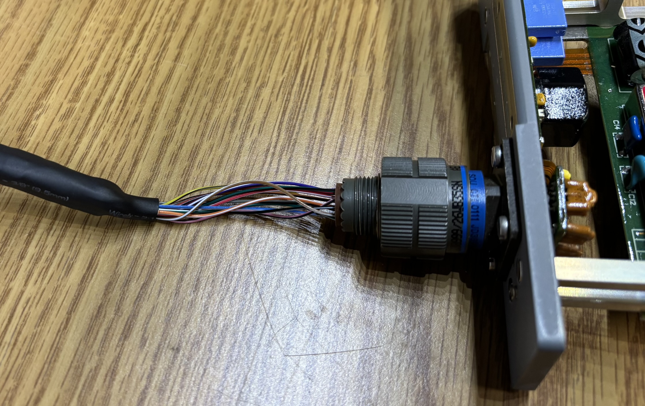
After deciphering the pin-out, we decided to purchase the mating plug for the Souriau twist-lock connector on the back. We found one on eBay manufactured by Amphenol Aerospace for a reasonable price. We must have mixed up the part number slightly as the plug we received was the correct size and pin configuration, but the keying did not match up with the connector. This was not an issue since we then decided to commit the absolute sin of filing down the keying on the plug so it would insert into the connector. This worked well but would definitely be unacceptable in an actual aircraft. Below is a picture of our "modified" plug. Also, we really wouldn't recommending filing these connectors since the coating is often "olive drab cadmium"...
We used the plug to build a custom wire harness and control box to operate the indicator as a display item.
When the indicator first receives power, it does a brief lamp test and sweep of the bar graph. After that, it just goes blank. This is likely due to the lack of any RS-485 communication or a dimmer input. Unfortunately, we really have no way to determine what to send it over the RS-485 interface. We eventually may write a program to send it random data until it responds. Luckily, connecting pin 12 to ground causes the unit to go into lamp test mode and endlessly sweep the bar graph, which looks pretty cool!