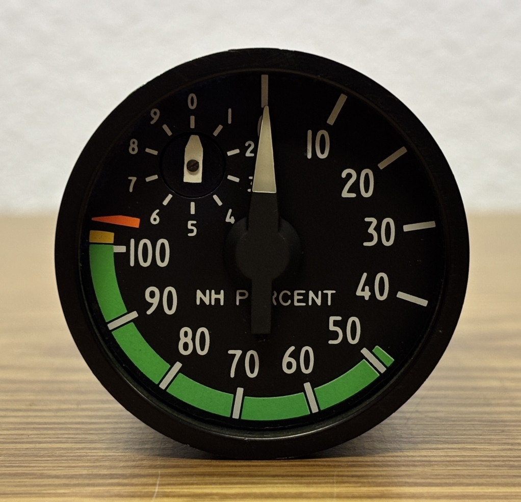
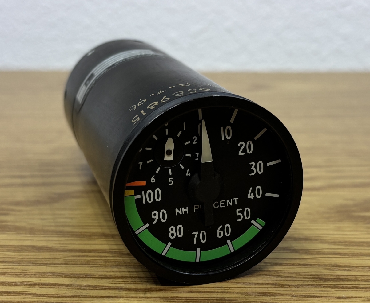
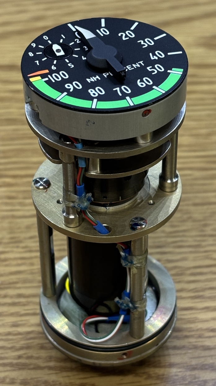
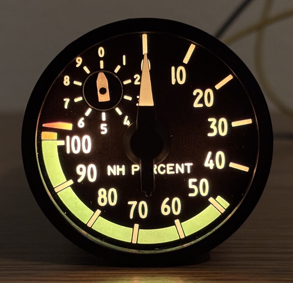
This tachometer indicator was purchased online as a surplus item from a decommissioned aircraft, likely a Westland Lynx Helicopter It is used to display the rotational speed of the power turbine or drive shaft as a percentage of the nominal reference speed. It does not represent RPM and is intended to be a way to ensure the power turbine is operating within its normal range. As indicated by the green section of the scale, 50-100% was likely considered normal or safe, with an excess of 100% being problematic. There is a smaller indicator in the top left that displays the ones digit of the percentage (eg. 57%), it's a "fine" readout that complements the "coarse" readout of the main gauge. The indicator is a metal cylindrical tube that somehow mounts into the panel of the cockpit. There is a piece of glass on the front with an anti-reflective coating that protects the dial plate and delicate indicator components.
On the side casing are some handwritten reference numbers and a couple of labels. They indicate that this device was made by JAEGER in Frame in 1982. It has a part number of 64520-722-3 and a serial number of 909.
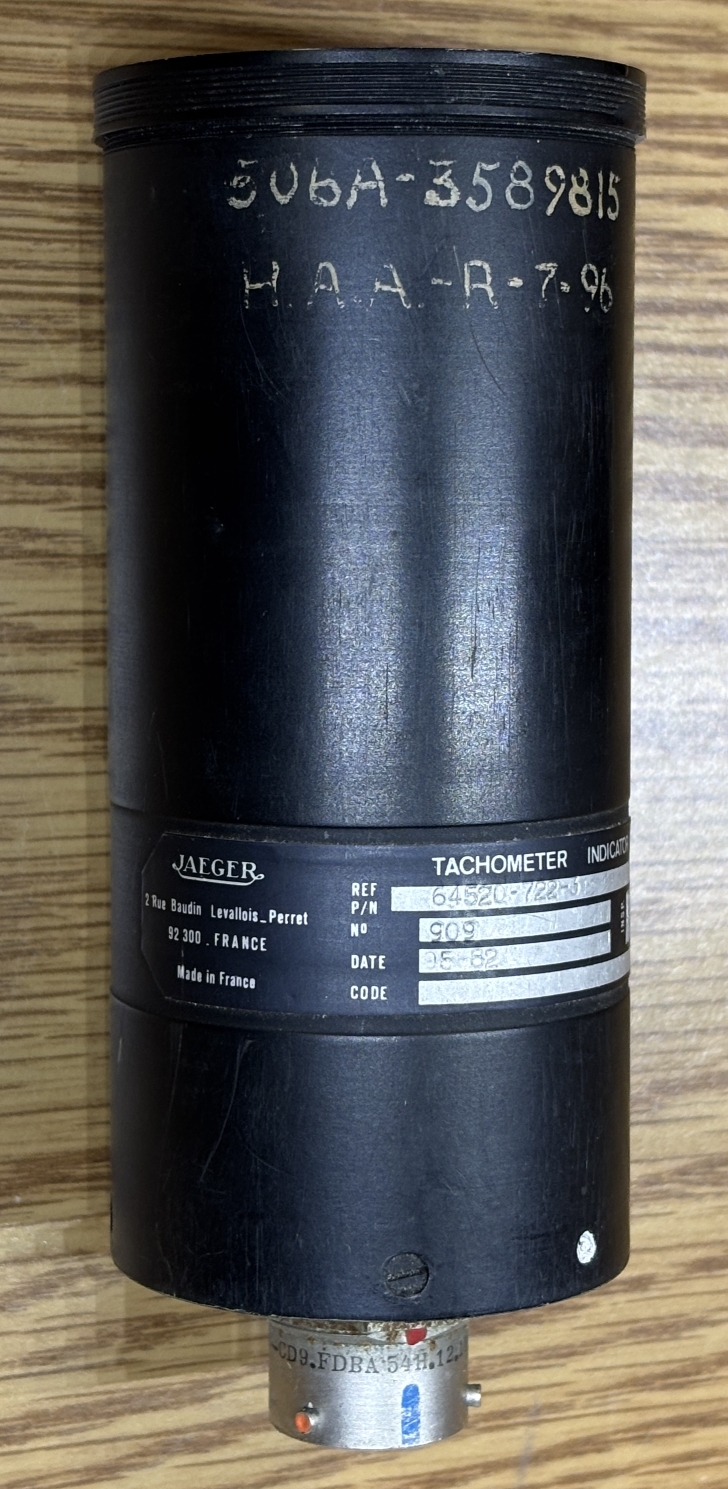
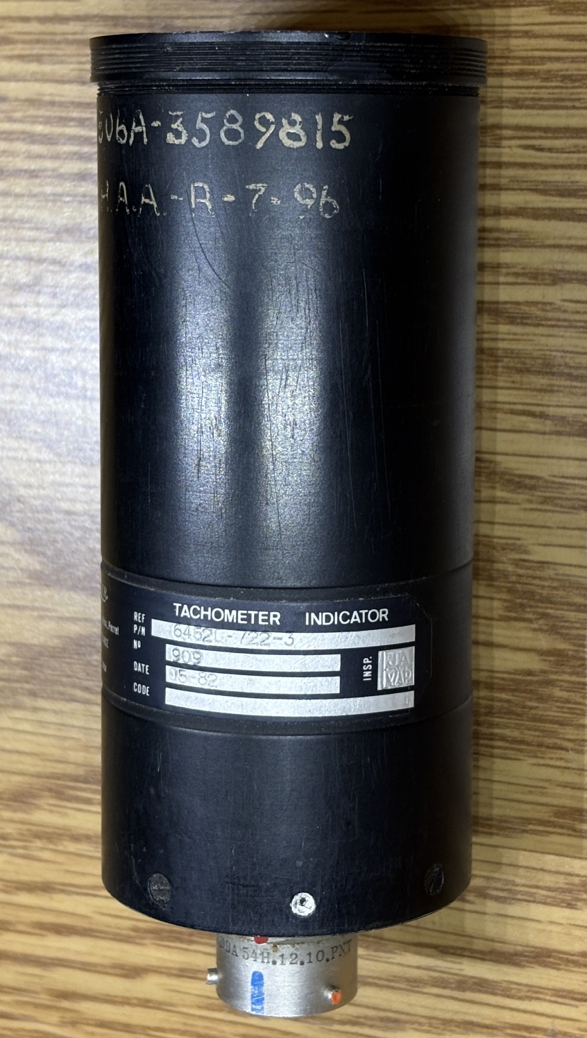
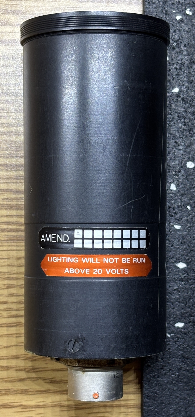
Further around the side casing are two additional labels. One being an amendment tag, which indicates modifications made to the unit, and the other being a very stern warning that states "lighting will not be run above 20 volts".
On the rear of the unit is just a single 10-pin mil-spec connector. A pin-out for this connector is provided below the image.
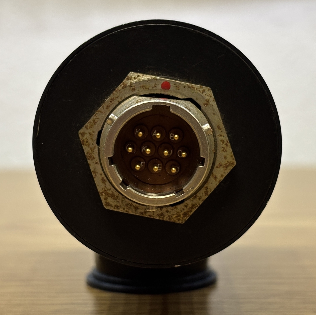
| PIN | FUNCTION |
|---|---|
| A | MOTOR PHASE 2 (RED) |
| B | MOTOR PHASE 3 (YELLOW) |
| C | MOTOR PHASE 1 (BLACK) |
| D | CHASSIS GROUND |
| E | ILLUMINATION COMMON (0V) |
| F | ILLUMINATION LEFT (5-20V) |
| G | ILLUMINATION RIGHT (5-20V) |
| H | N/C |
| J | N/C |
| K | N/C |
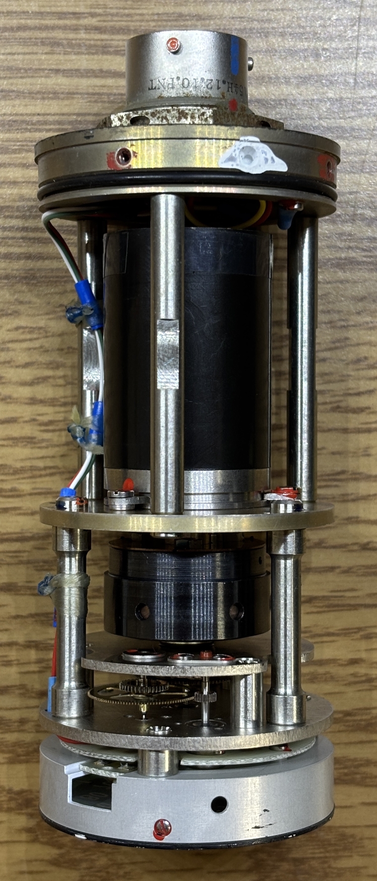
Removing four slotted screws 90-degrees apart on the rear of the casing allow the components assembly to slide out of the metal housing. There is a gasket that keeps the unit sealed.
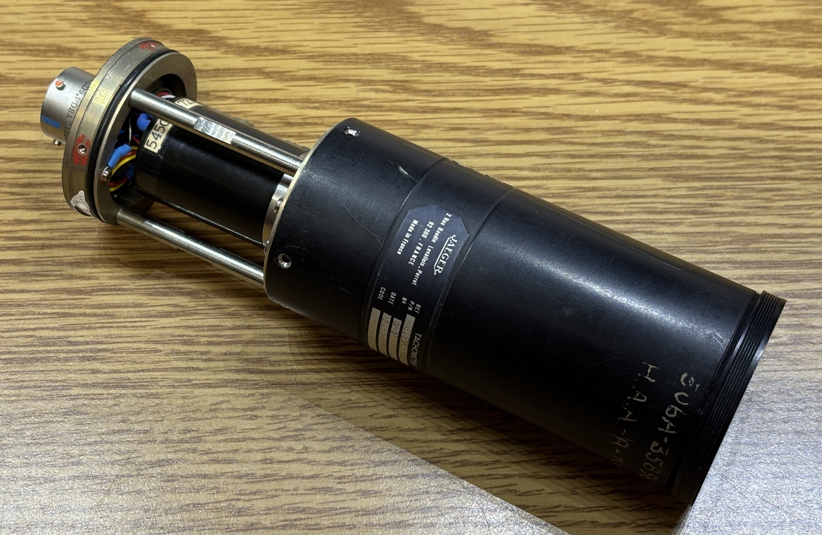
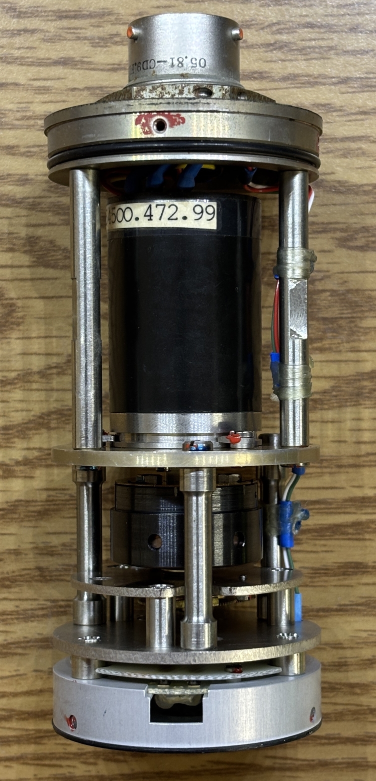
With the internal assembly removed from the housing, we can see the workmanship and quality that went into just a simple indicator. Like many aircraft components, it uses high quality components and manufacturing techniques.
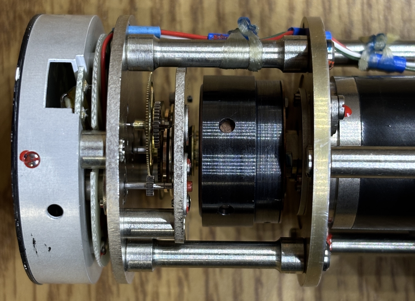
Unfortunately, the only markings on the motor (54500.472.99) return no useful results. The manual we linked at the bottom of this page does give use some useful information from a similar tachometer, which can likely be applied to this one as well. According to the manual, it's a 3-phase synchronous motor that is driven by a tachometer generator. The frequency of the alternating current supplied by the generator is proportional to the speed being measured. The output of the motor is coupled to a magnetic tachometric unit. This unit is a complex arrangement of permanent magnets that utilize Eddy currents induced by the rotation of a permanent magnet on the motor's output shaft to move the measuring drum. Lastly, this output is coupled to a movement mechanism, which uses a gear train to display the result using a calibrated scale.
Here is a closer look at the magnetic tachometric unit and movement gear-train.
Applying power to the illumination pins lights up the small incandescent bulbs behind the dial plate, making the readout visible at night. Just remember not to exceed 20 volts!
We encourage you to check out the manual linked below, as it explains in detail how these units work. It's for a slightly different model of tachometer indicator manufactured by JAEGER, but follows a very similar design principle.