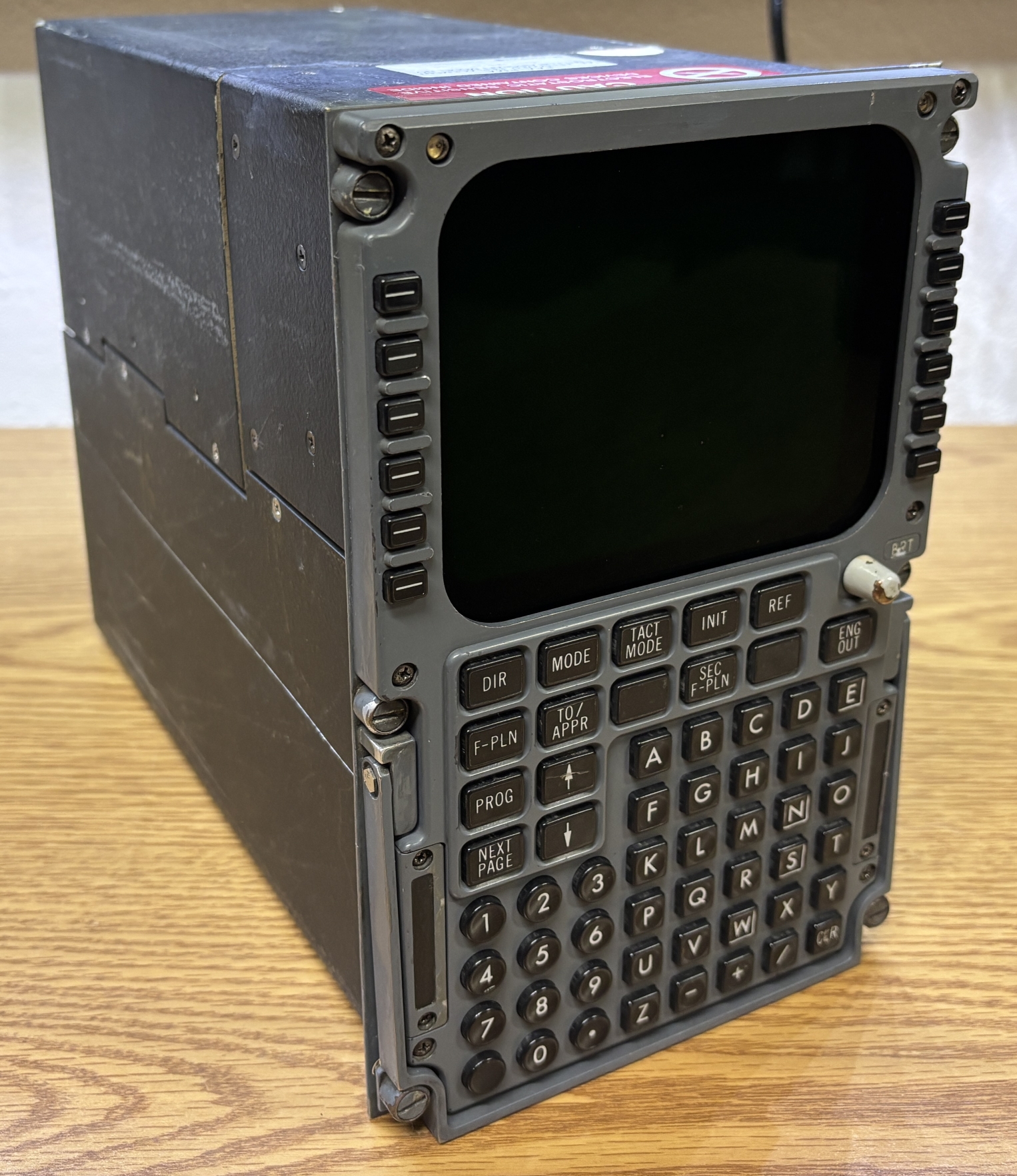
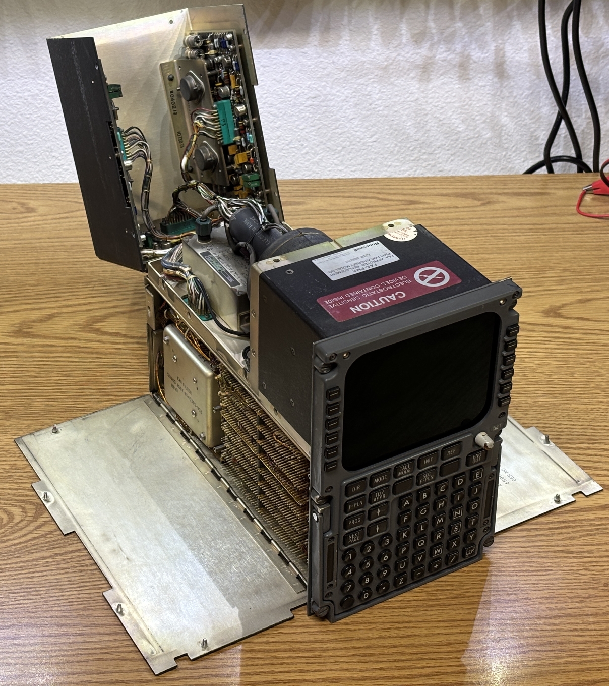
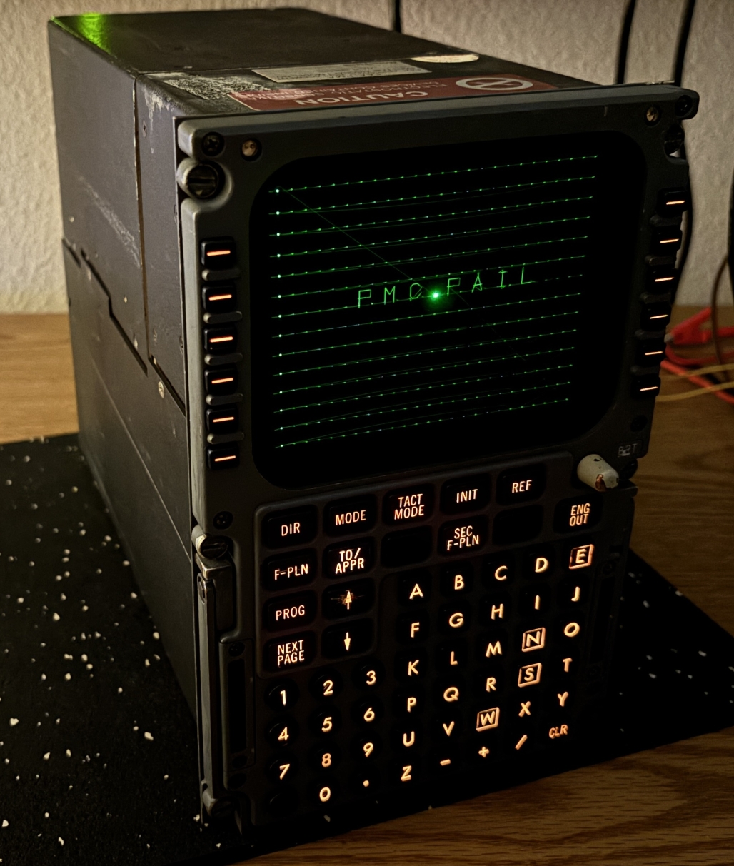
The Control Display Unit or CDU is the pilot's interface for the onboard flight computer of the aircraft. Think of it like an HMI for interfacing with a PLC or commercial automation system. The CDU does little to no actual processing or control, and just transmits keyboard input back to the flight management computer and outputs data from the computer to the built-in display for the pilot to view and interpret. In the majority of commercial aircraft, there are two functionally equivalent CDUs installed in the cockpit for redundancy. This particular CDU was likely salvaged from an Airbus A310-series aircraft, based on the label on the top. Also, the FedEx document linked on the bottom of this page contains references to this model of CDU and was written for an Airbus A310-300. When installed in the cockpit, the only side of the CDU accessible is the front. The top half of the CDU is consumed by a small single-color CRT display. Above the display on both top corners are two photosensors (likely for automatic brightness adjustment). There is also an adjustment knob labeled BRT which can also be used to adjust the display brightness. There are a variety of buttons on the CDU that the pilot can use to adjust FMS parameters and perform tasks such as entering flight plan data. There are 4 groups of buttons. First are 12 soft-keys, 6 on each side of the CRT display. These are used to make selections based on what's displayed on screen. Next are several function keys that execute specific tasks or open menus. After that is a numerical keypad, and finally a traditional A-Z keyboard with letters, a few symbols, and a clear key.
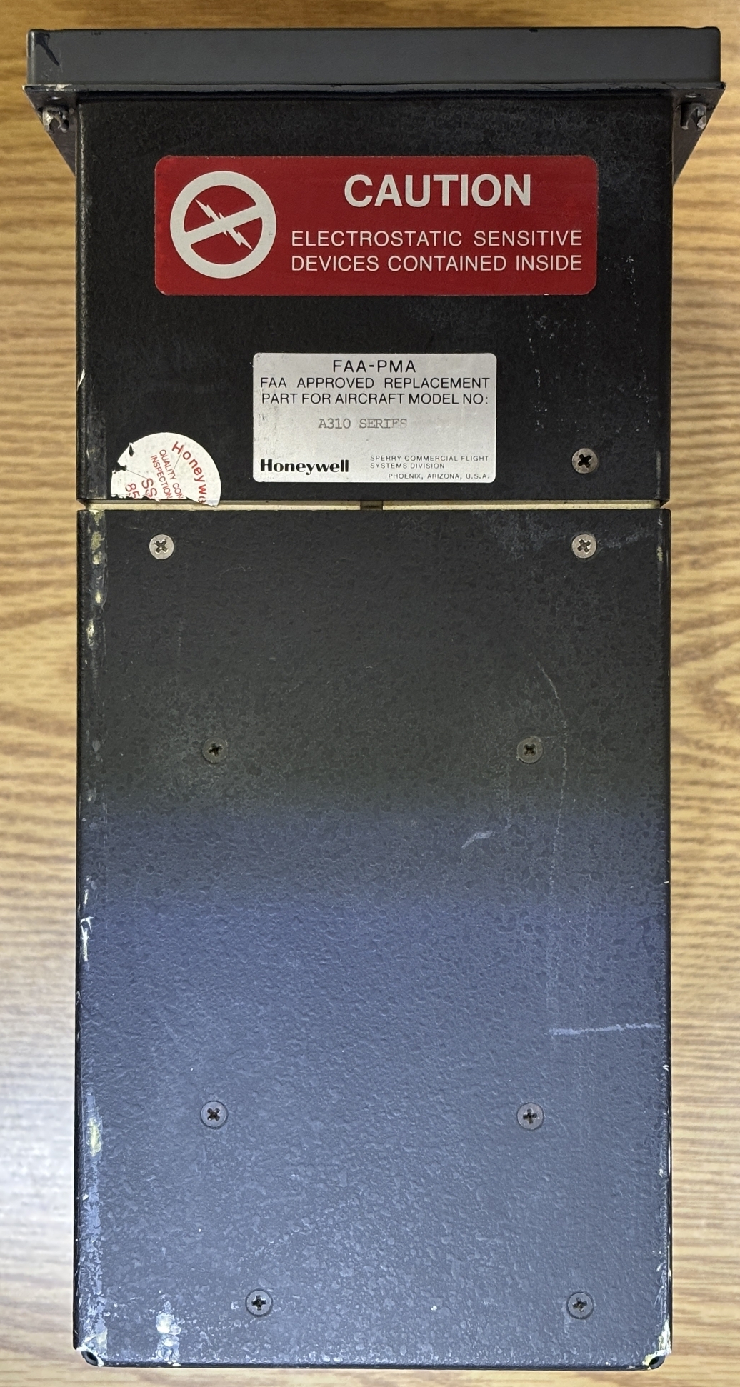
On the top of the unit are some screws that secure the case panels along with a couple of labels. One warns of electrostatic sensitive devices contained within, the other states that it's an FAA approved replacement part for the Airbus A310 series planes. The detailed information label is on the back of the unit. It contains the model/part number (4043912-902), sub-model/identifier (65-8371-06-00), serial number, and modifications. There is no date or inspection stamp. This instrument is quite old as evident by the text that reads "Sperry Commercial Flight Systems Division". Sperry Aerospace Group was later sold to Honeywell. Lastly, there are two mil-spec twist-lock connectors on the back. One is normally capped while the other connects to the aircraft wiring harness.
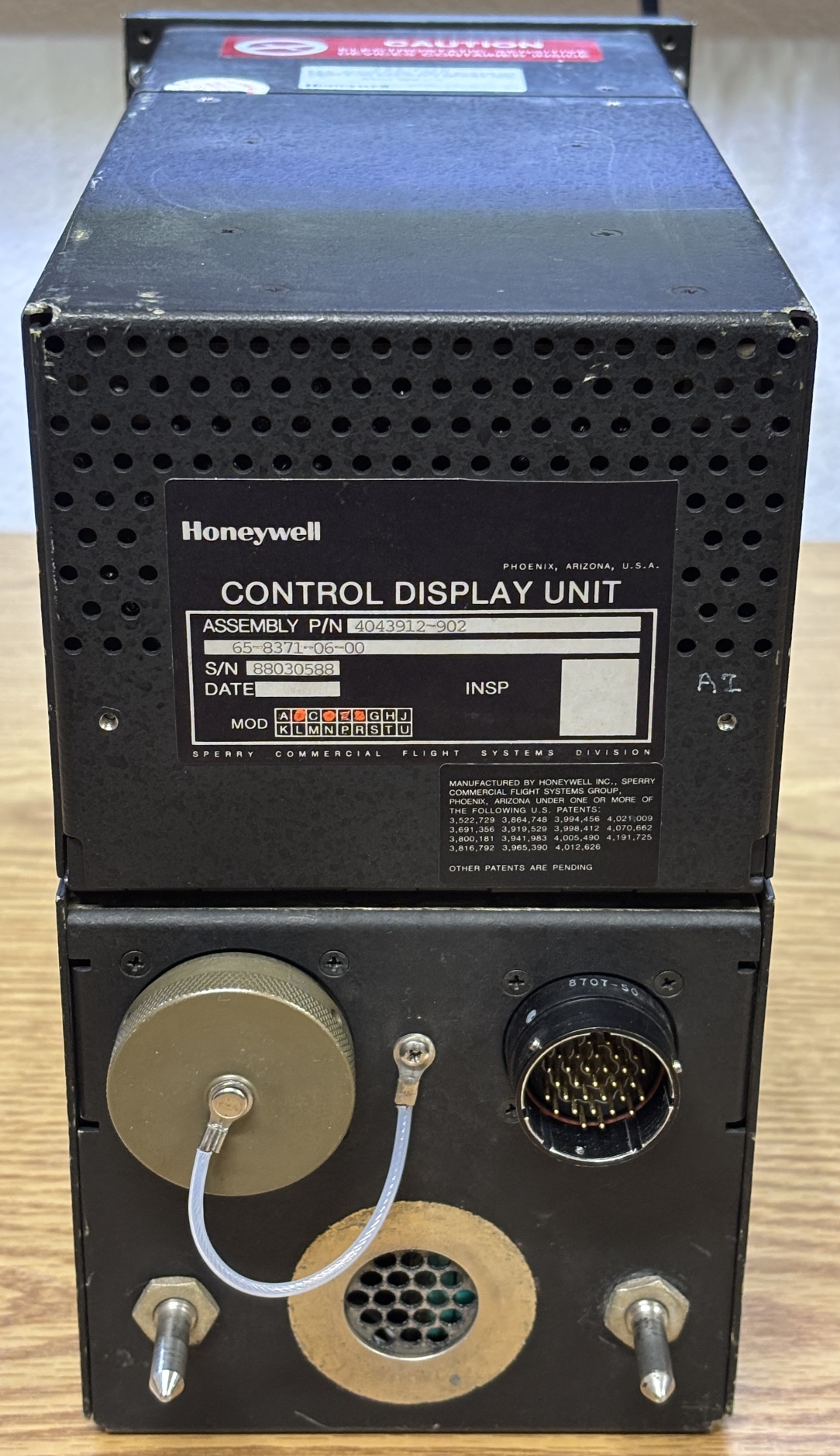
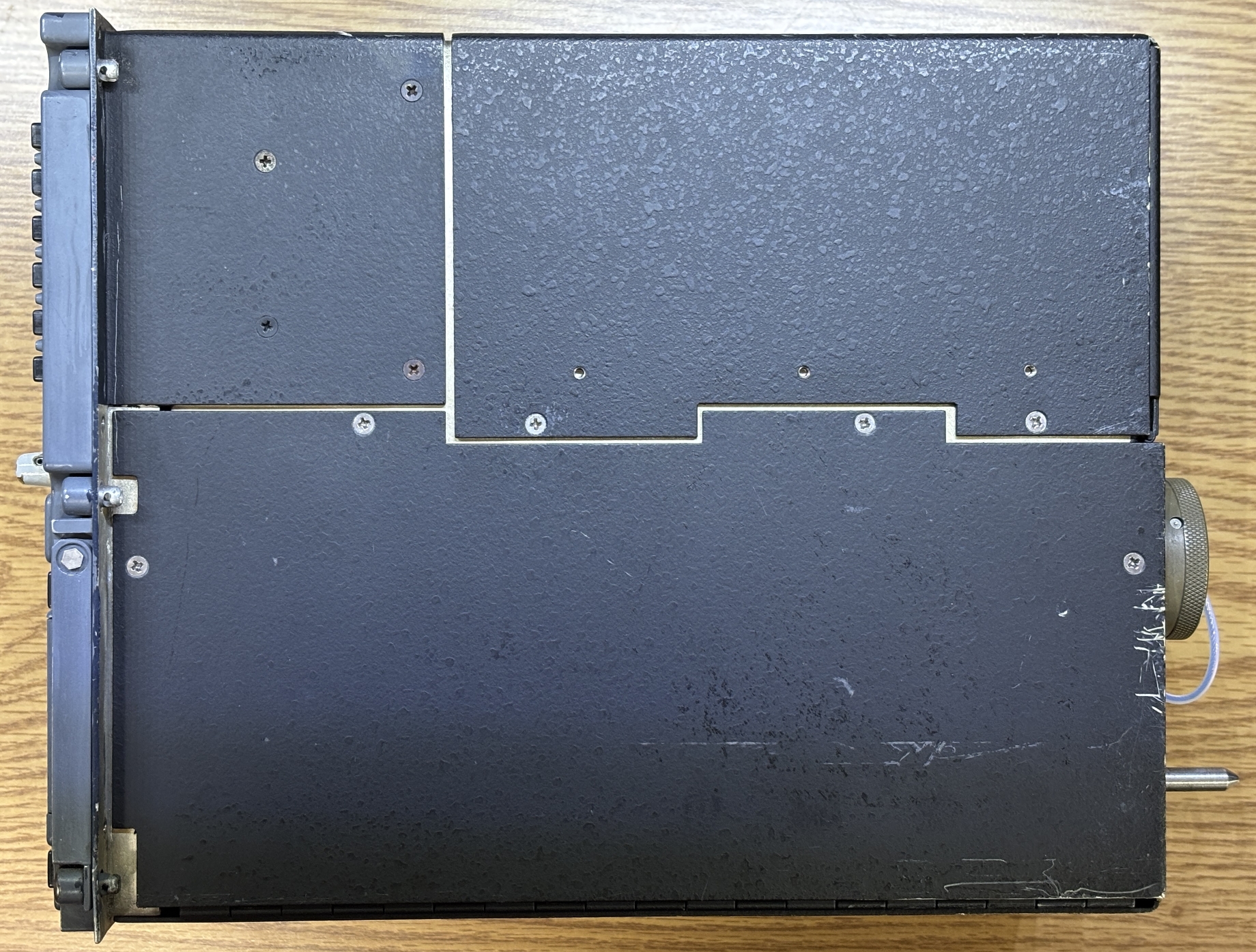
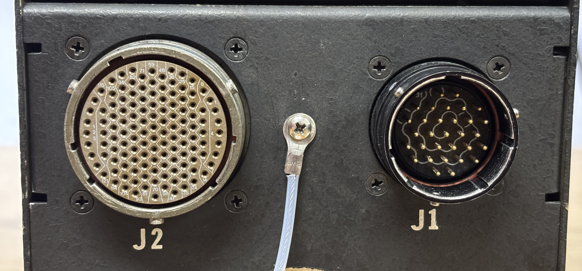
On the side there are three distinct side panel sections that are secured to an inner frame by phillips screws. Taking a closer look at the electrical connectors, J1 is a 31-pin male connector and the normally capped one is a female 128-pin connector labeled J2. The capped connector was puzzling at first, as it would be strange to have a permanently attached cap for a device that is always installed and wired into the aircraft. Wouldn't the cap dangle and make noise during flight? After we opened up and examined this unit, we believe this is just a programming/debug/test connector used when the device is not installed in an aircraft. This is because all the wiring from this connector goes directly to the logic boards within and bypasses the internal power supply. Some of the connections from J1 go to an EMI filter and internal power supply. Based on our testing, all the required aircraft connections (for normal flight) are present within the J1 connector. This would also explain the permanently attached cap on J2.
Below is a partial pin-out of the J1 connector.
| PIN | FUNCTION |
|---|---|
| 23 | BITE (LAMP TEST - GROUND TO ENABLE) |
| 24 | |
| 25 | CHASSIS GROUND |
| 26 | |
| 27 | |
| 28 | KEYBOARD BACKLIGHT (5V) |
| 29 | KEYBOARD BACKLIGHT (0V) |
| 30 | POWER INPUT (115 VAC 400 HZ) |
| 31 | POWER INPUT (115 VAC 400 HZ - RETURN) |
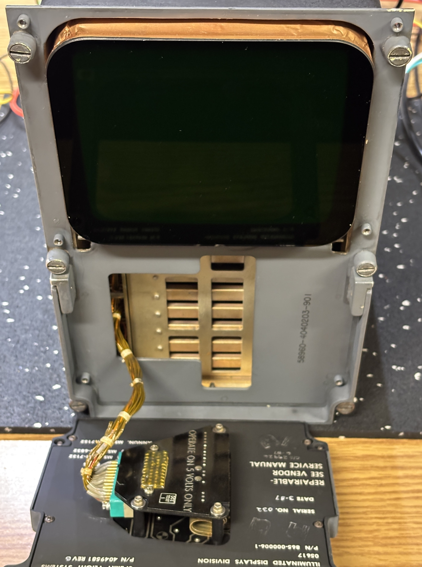
We'll start by removing the front control panel and keyboard assembly. Removing 6 philips screws allow it to be pulled away from the housing. A high-density connector must be removed from a socket on the front panel. It looks like magnet wire or something similar was used for the front panel connection (along with other internal connections). The wire is pretty stiff and seems to be coated with some sort of enamel. The front surface and frame of the CRT is also visible, the sides of the tube are covered in copper foil.
With this type of connector, it's imperative to loosen the screws on both sides evenly to separate the connector from the socket without bending the pins.
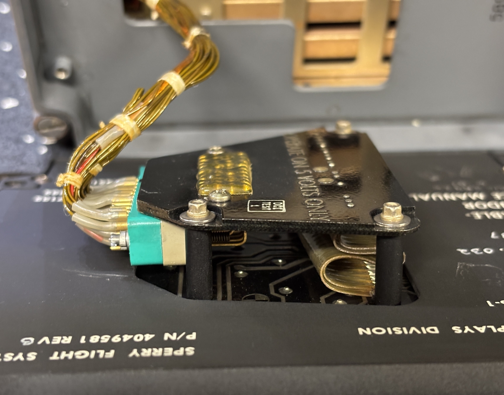
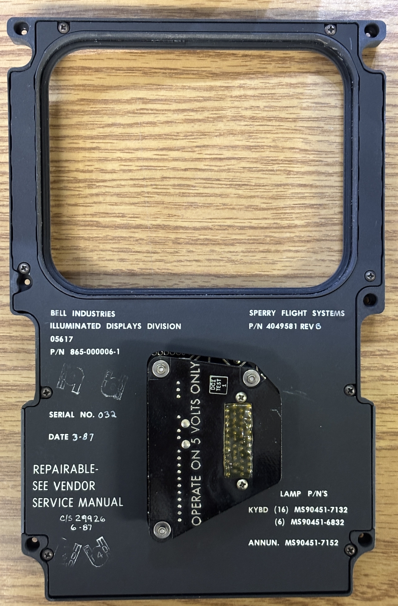
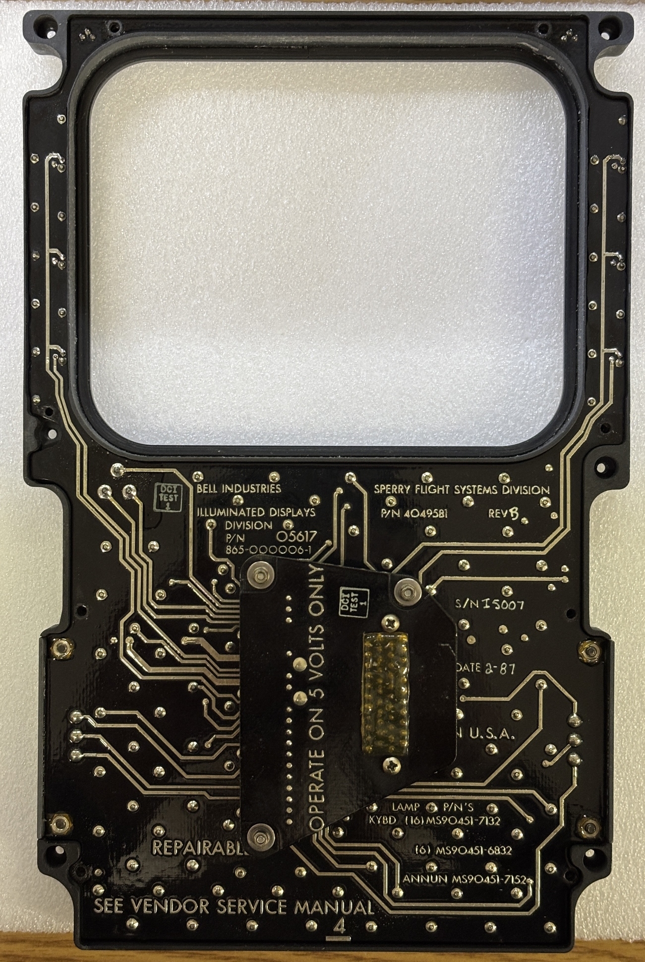
With the front panel fully removed, there are a few notable features on the back. This panel was made by the illuminated displays division of Bell Industries in 1987. It has a Bell part number of 865-000006-1 and a Sperry Flight Systems part number of 4049581. Conveniently, it explicitly states that it's a repairable device and even lists the incandescent lamp part numbers in the corner should they need to be replaced. A small section of circuit board protrudes from a hole in the plastic backing and is where the socket is located. According to the silkscreen, the unit should only be operated on 5 volts.
Removing the 8 philips screws allows the plastic backing to be removed from the front panel assembly, exposing the circuit board. The board is a very traditional design from the 80s with heavy traces and what could be silver solder. The silkscreen also contains much of the same information printed on the backplate.
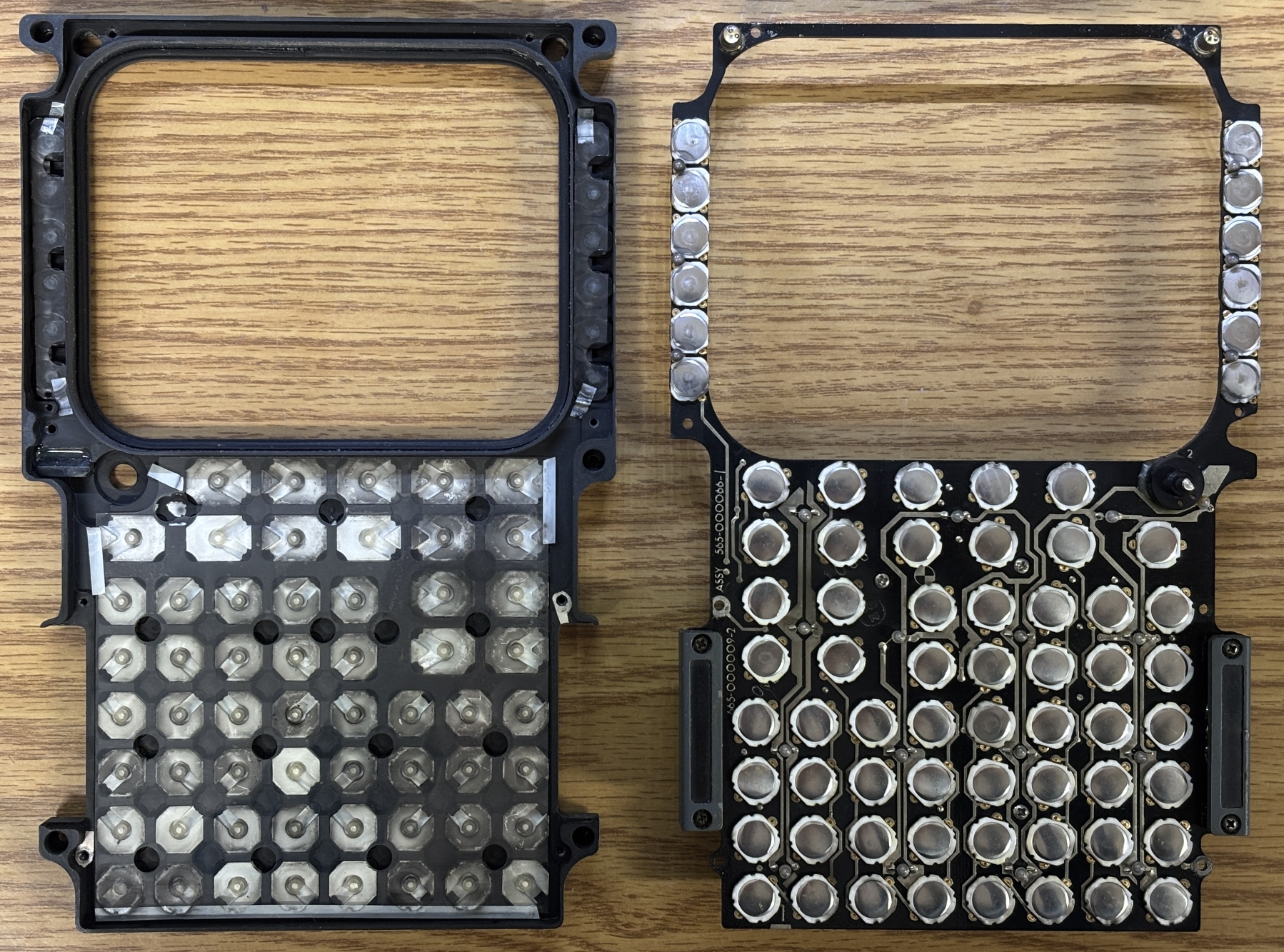
Removing the screws on the annunciator lamp covers allow the board to be fully removed from the frame. With the board removed and flipped over, we can see all of the tactile pushbuttons and tiny incandescent lamps for the backlight. On the panel frame are the individual plastic keys with translucent sections for light to pass through. There are thin sheets of plastic in between the keys and tactile pushbutton switches. While we had the panel open, we removed and washed all the keys as some were quite dirty. There was significant dust and grime build up on the surface around the keys as well. We then painstakingly re-installed all the keys in their proper spot and orientation.
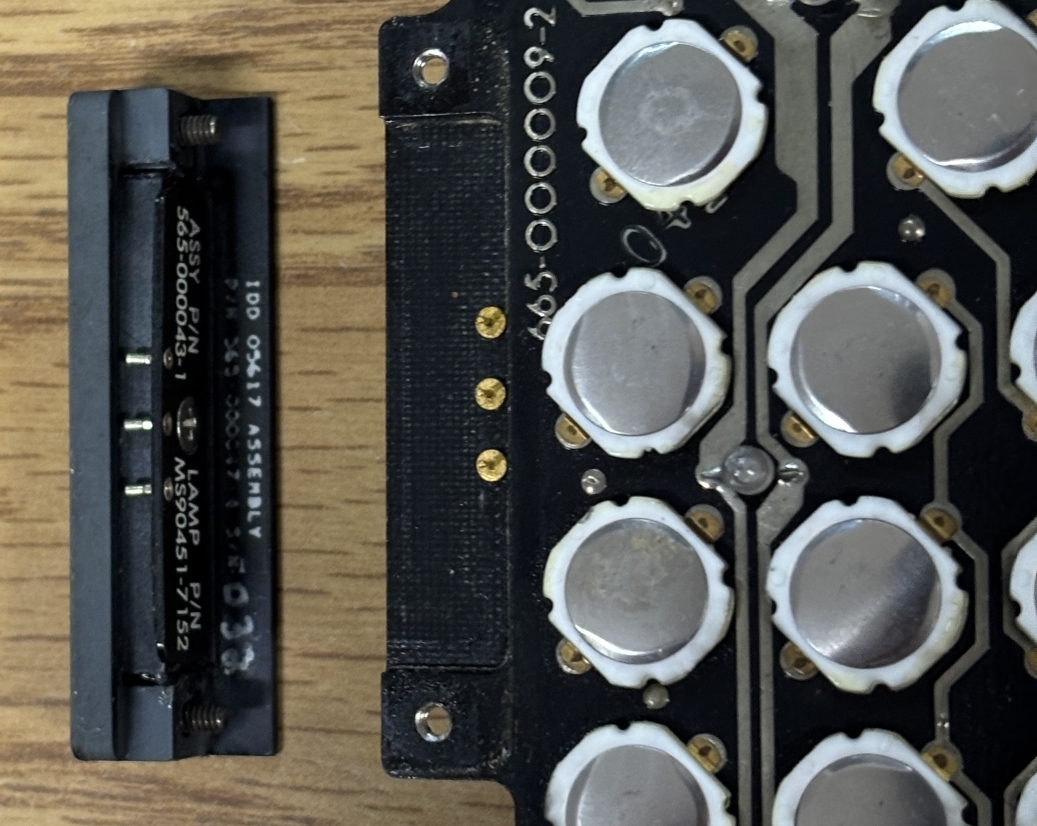
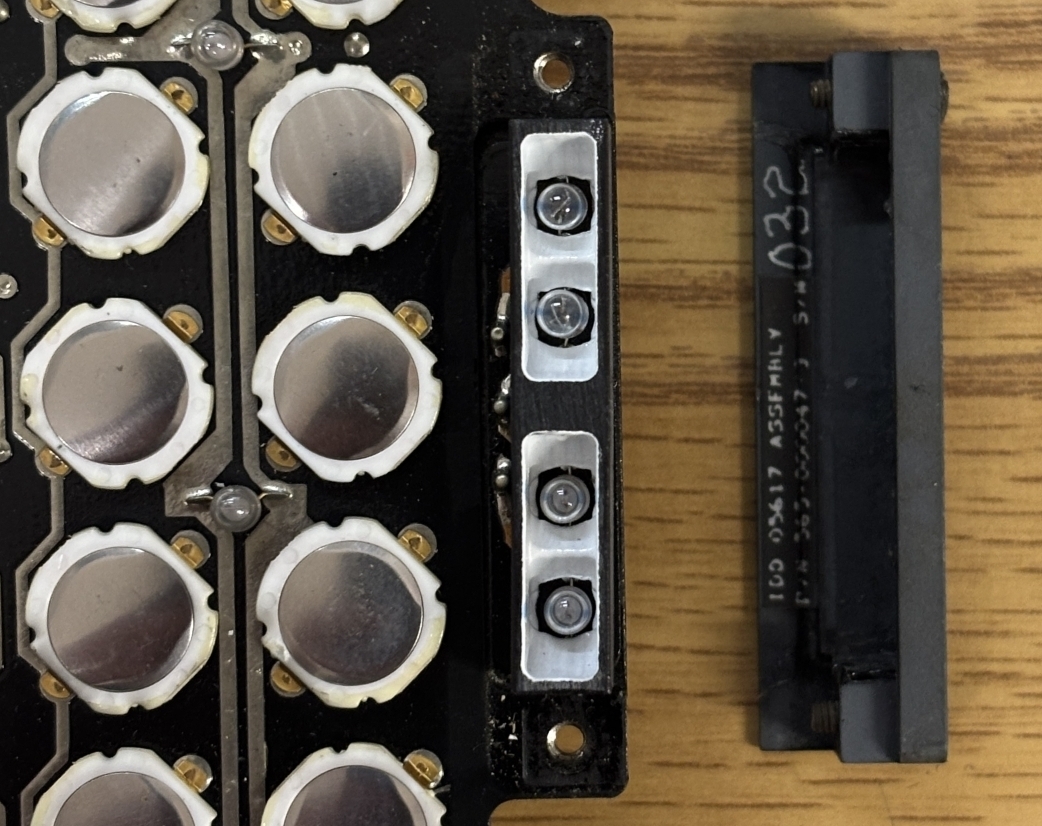
These are the annunciator indicator modules on either side of the keypad. They can be removed by loosening the two phillips screws and then pulling them off the 3 pins. The center pin is the common while the top and bottom illuminate their respective indicators. Each indicator has two incandescent bulbs.
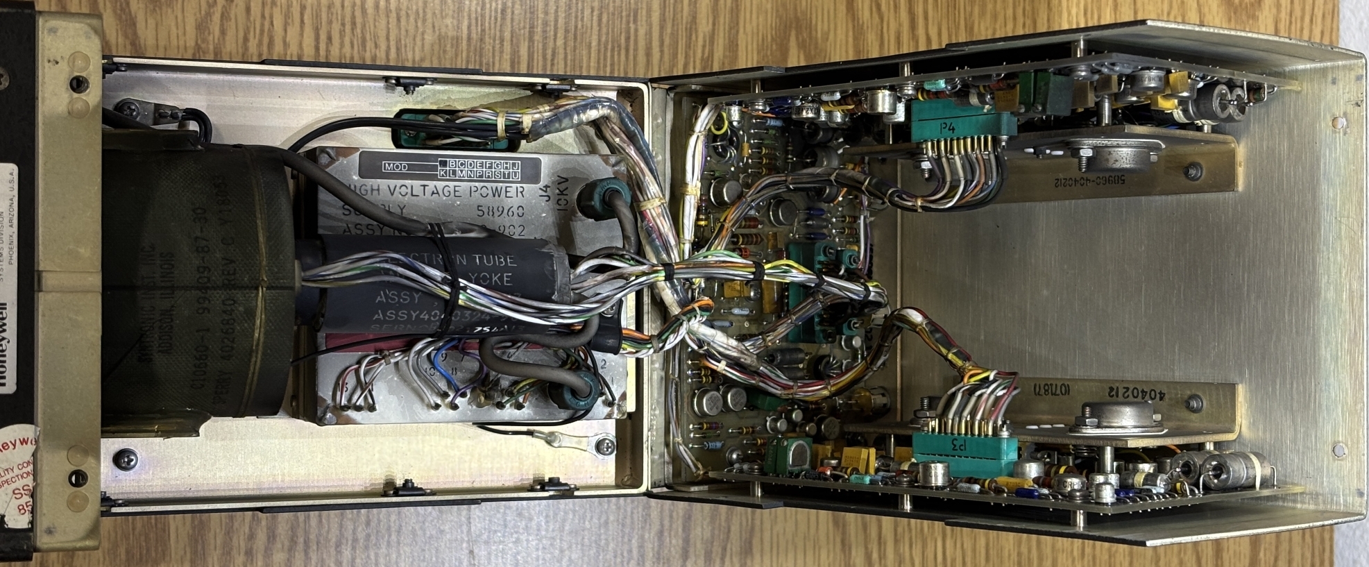
The rest of the CDU opens up quite nicely. There are 3 hinged case panels that open up to reveal the components inside. Here is an image with all the hinged panels opened up. The top panel reveals the CRT, high voltage power supply, and related control electronics. One side provides access to the circuit boards, and the other side provides access to the rear side of the backplane and associated wiring.
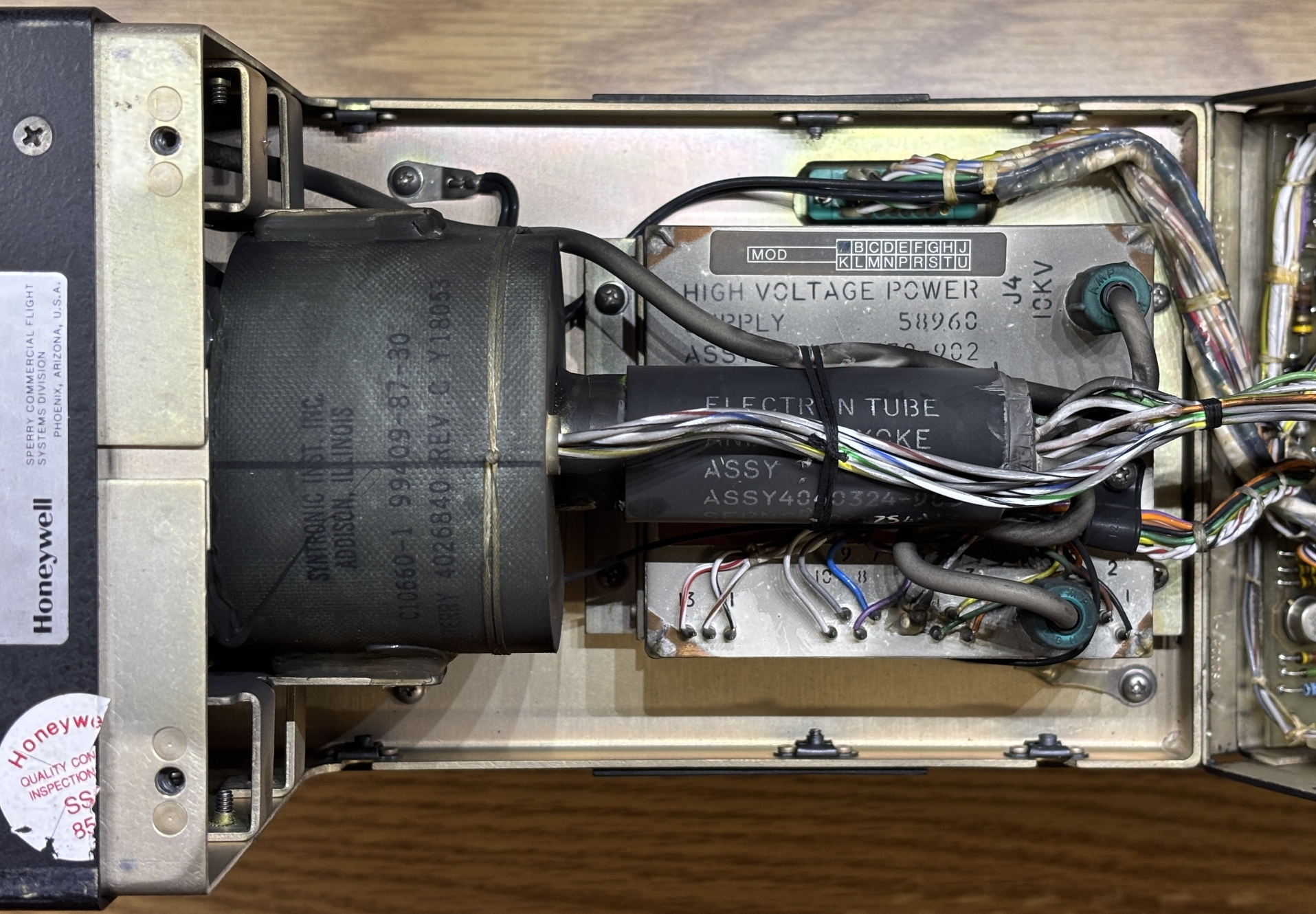
This is the CRT section of the CDU. It's very tightly packed and includes all the components needed to drive the small CRT along with the CRT itself. The tube assembly and deflection yoke is mounted to the inner metal frame. Below the tube is the high voltage power supply. There are 3 circuit boards mounted to the sides of the hinged panel. There is just enough room for the boards and wiring to clear the sides of the tube when the panel is closed.
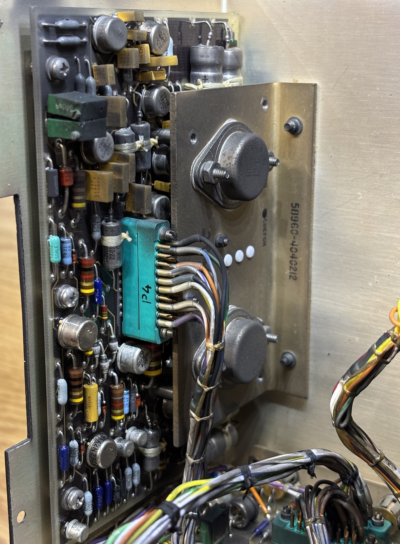
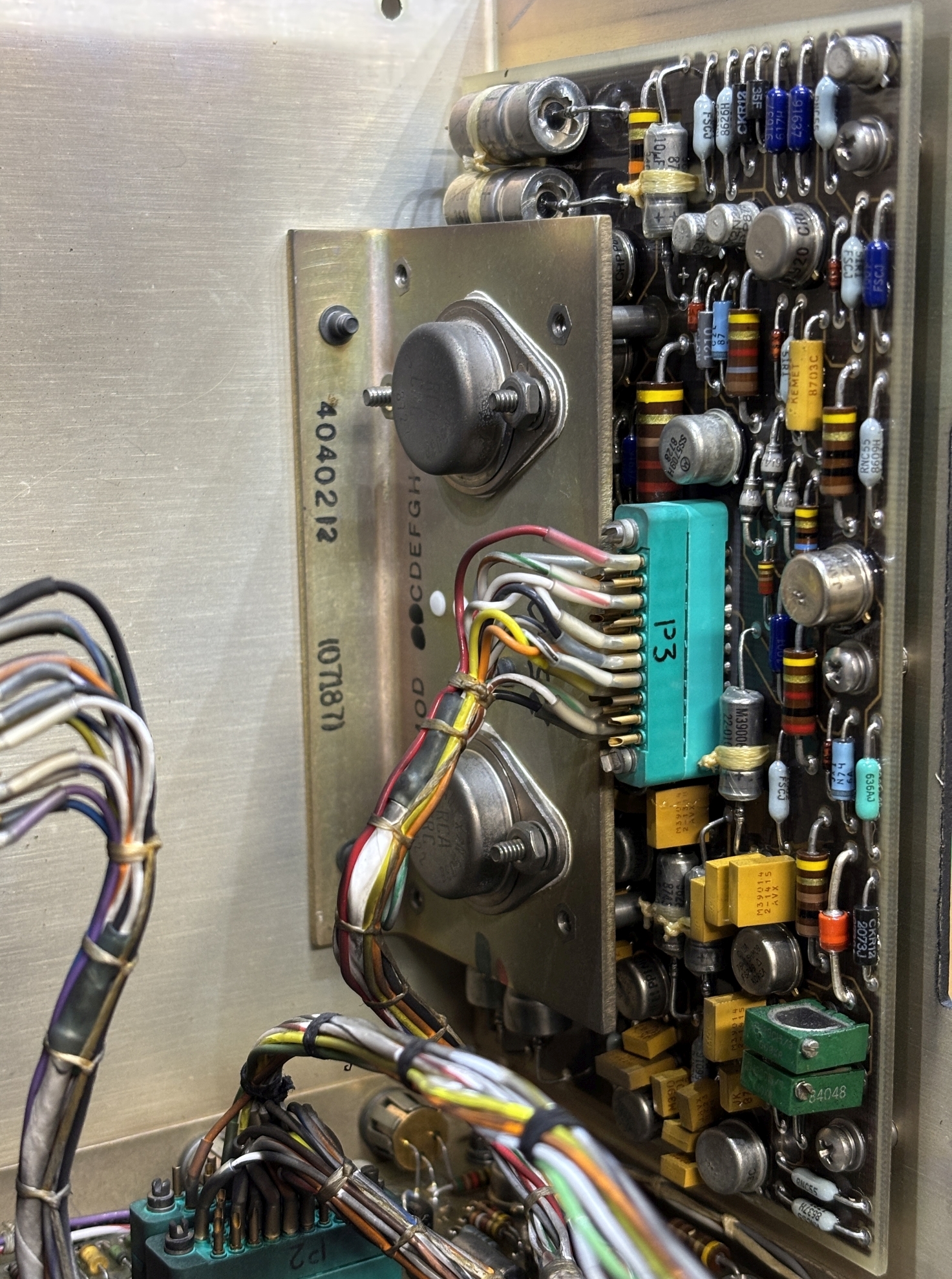
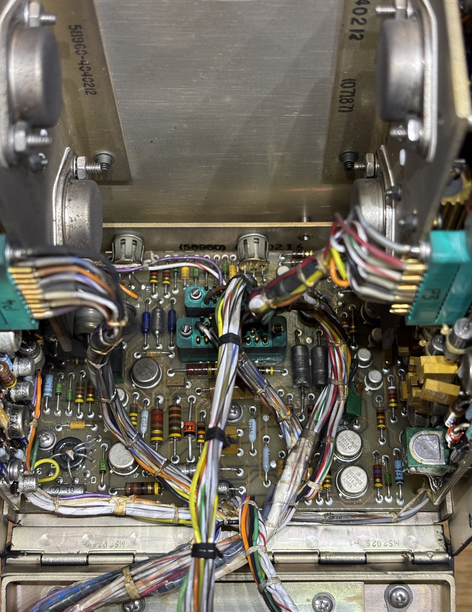
These boards are mounted on either side of the top hinged panel. We speculate that these are the X and Y deflection control boards since they appear to be mirror images of each other. Both boards are accompanied by a couple of transistors mounted to right-angle brackets placed in front of the boards. We originally thought the board on the left released the magic smoke and failed in some manner, but this turned out to just be some sort of aircraft dust that is present in several other areas of the CDU.
This board is mounted on the rear of the hinged panel and interfaces with the other two CRT boards along with the high voltage power supply. We presume it's a monitoring and control board for the CRT assembly.
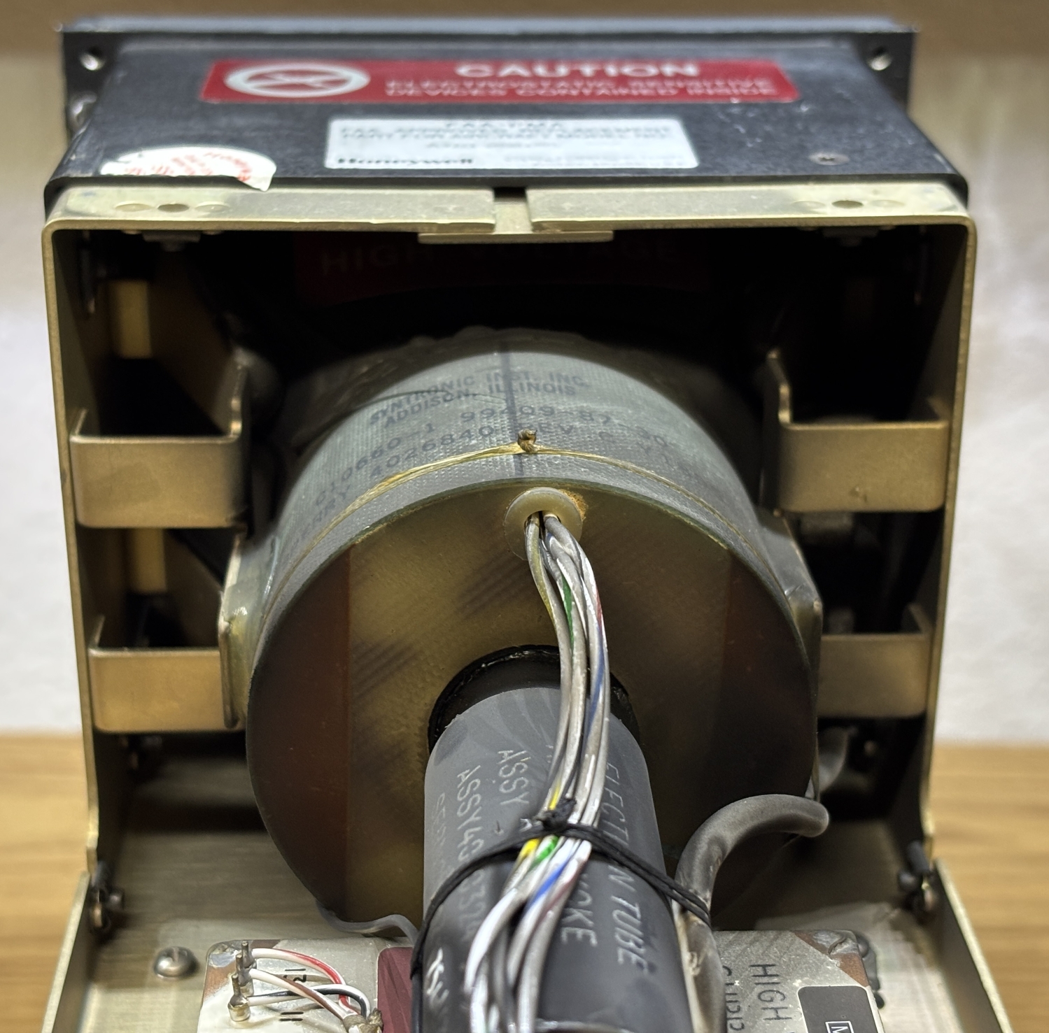
Here is the small CRT tube and deflection yoke that surrounds it. The wires that exit from the cylinder surrounding the tube are used to drive the deflection coils, likely by the boards mentioned earlier. CRT display tubes are fascinating feats of engineering. A glass tube is pulled to a vacuum and contains a phosphor coating on the inside of the front surface. An electron gun contained within the thin neck of the tube emits electron beams that illuminate the phosphor coating on the tube surface when they collide with it. The deflection yoke is a series of magnetic coils around the neck of the tube that can be energized to steer the beam, thus drawing an image on the screen. This is a single-color (green) CRT, much like the ones found in older oscilloscopes. Mounted directly below the tube is the high voltage power supply in a metal case. All high voltage connections look like they are sealed and insulated well, which helps to prevent leakage. The exposed solder pins are just for input power and monitoring of the high voltage power supply. According to the technical documentation linked at the bottom of this page, this CRT assembly has a phosphor protection circuit (likely to prevent burn-in) and also has the ability to monitor the high voltage power supply. Presumably, the CDU is able to detect a failed CRT tube, electron gun, or power supply and illuminate a warning indicator accordingly.
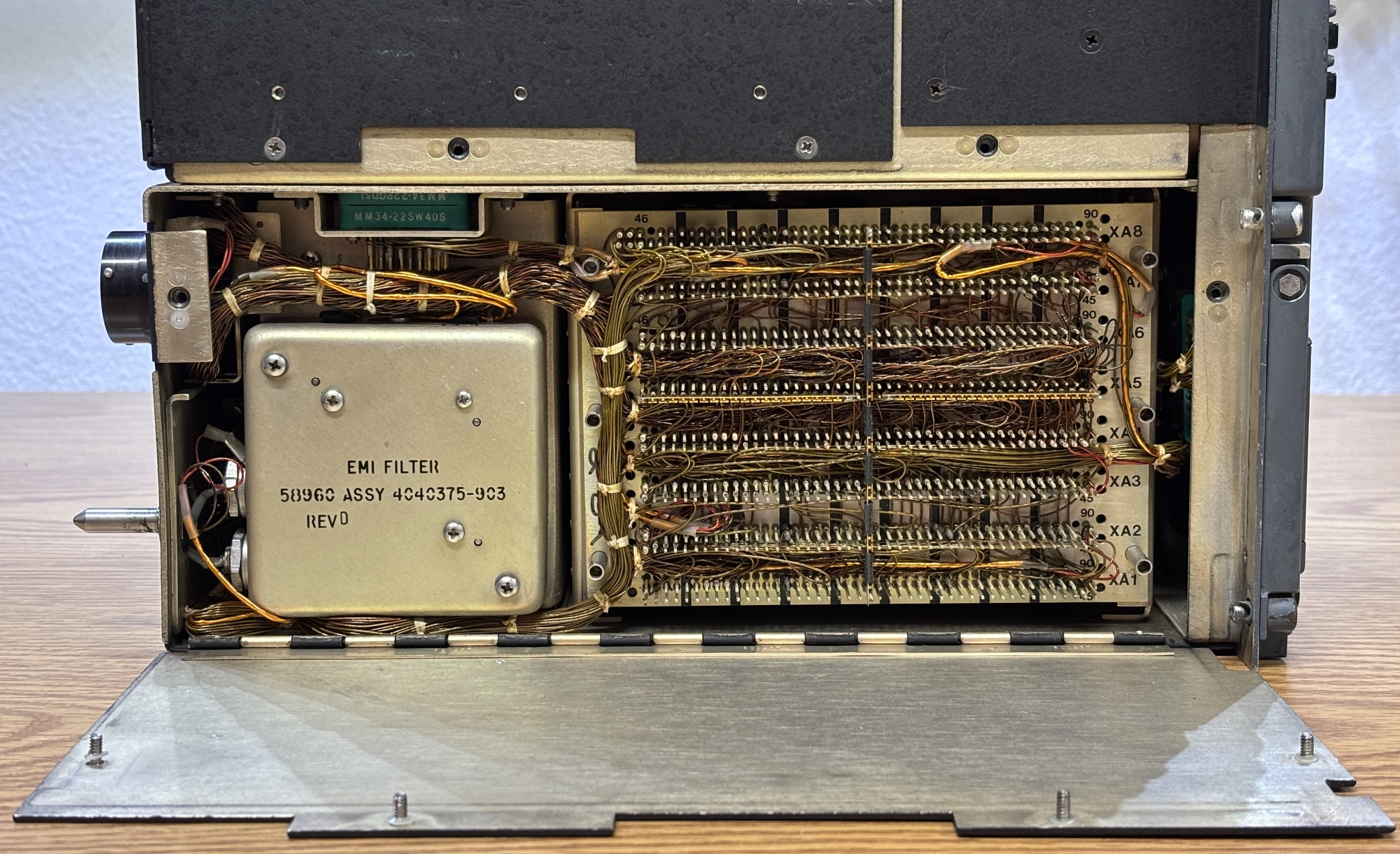
Behind the left-side access panel is the rear of the internal backplane along with a massive amount of wiring. The wire resembles magnet wire and has a similar coating and pliability. Each wire seems to be individually wrapped around the designated pin from the backplane. A large loom of wire goes to the front panel connector, while another goes to the connectors on the back of the CDU. The green connector on the top left is for the CRT section above and feeds power and control signals to the CRT assembly. Below that connector on the left is the EMI filter.
Removing the EMI filter and flipping it around allows us to take a look inside. There's not much to it, just some transformers and filtering devices for the AC input.
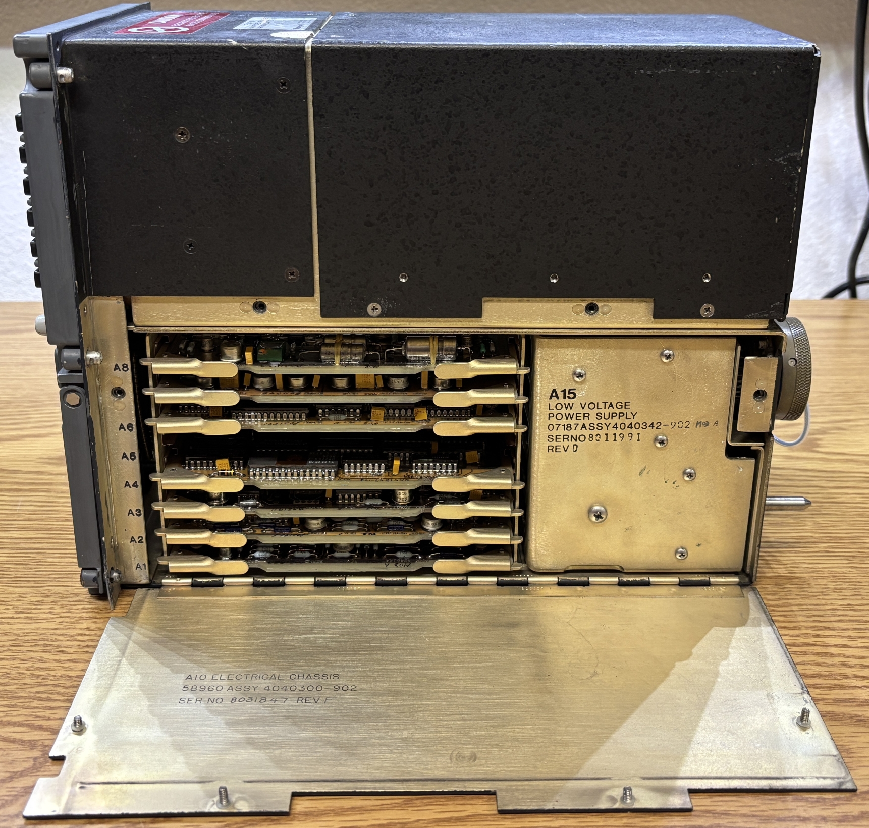
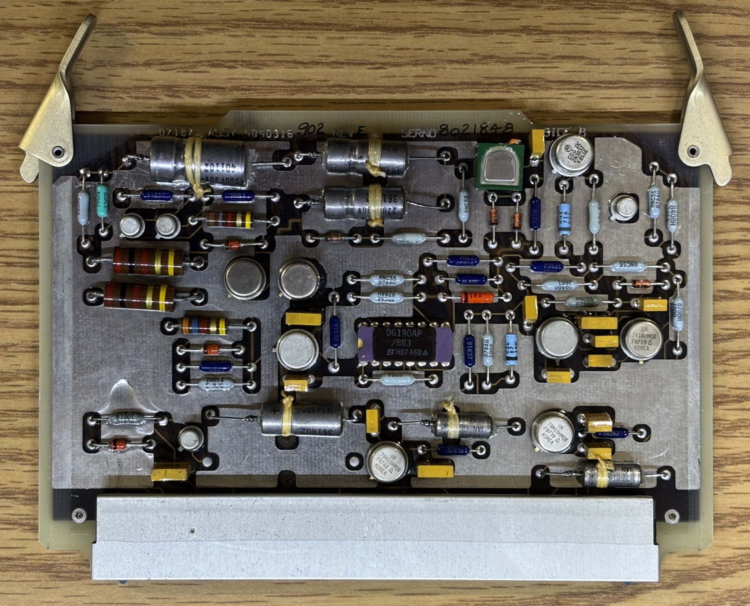
Behind the right-side access panel are several circuit cards slotted into the backplane. Towards the back is the low voltage power supply which converts 115 VAC 400Hz to various DC voltages suitable for the digital circuitry and CRT. All card slots except for A5 were originally populated.
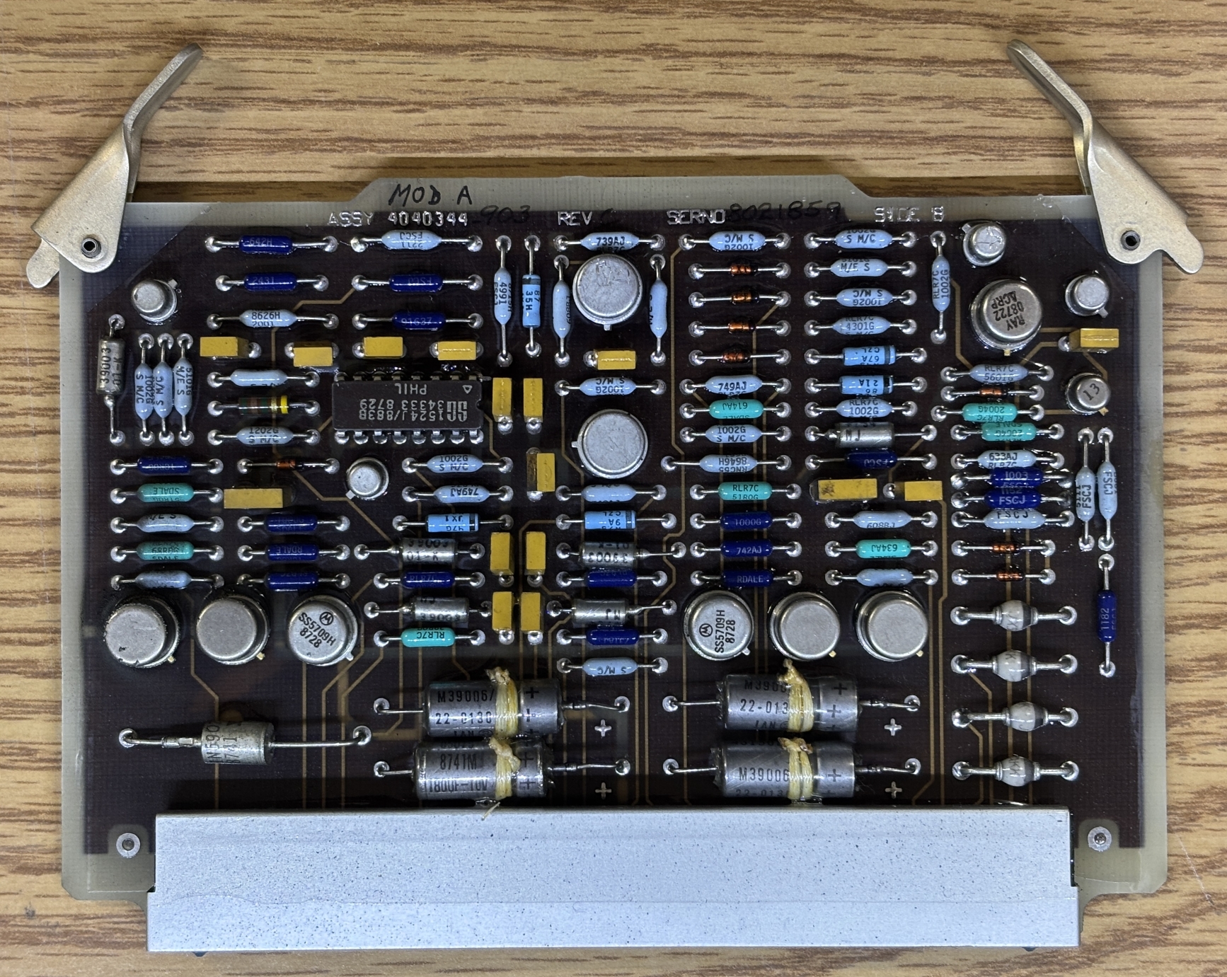
This card contains quite a few high-quality resistors, transistors, diodes, and capacitors along with a single SG1524 pulse width modulator chip. All of the cards are conformally coated..
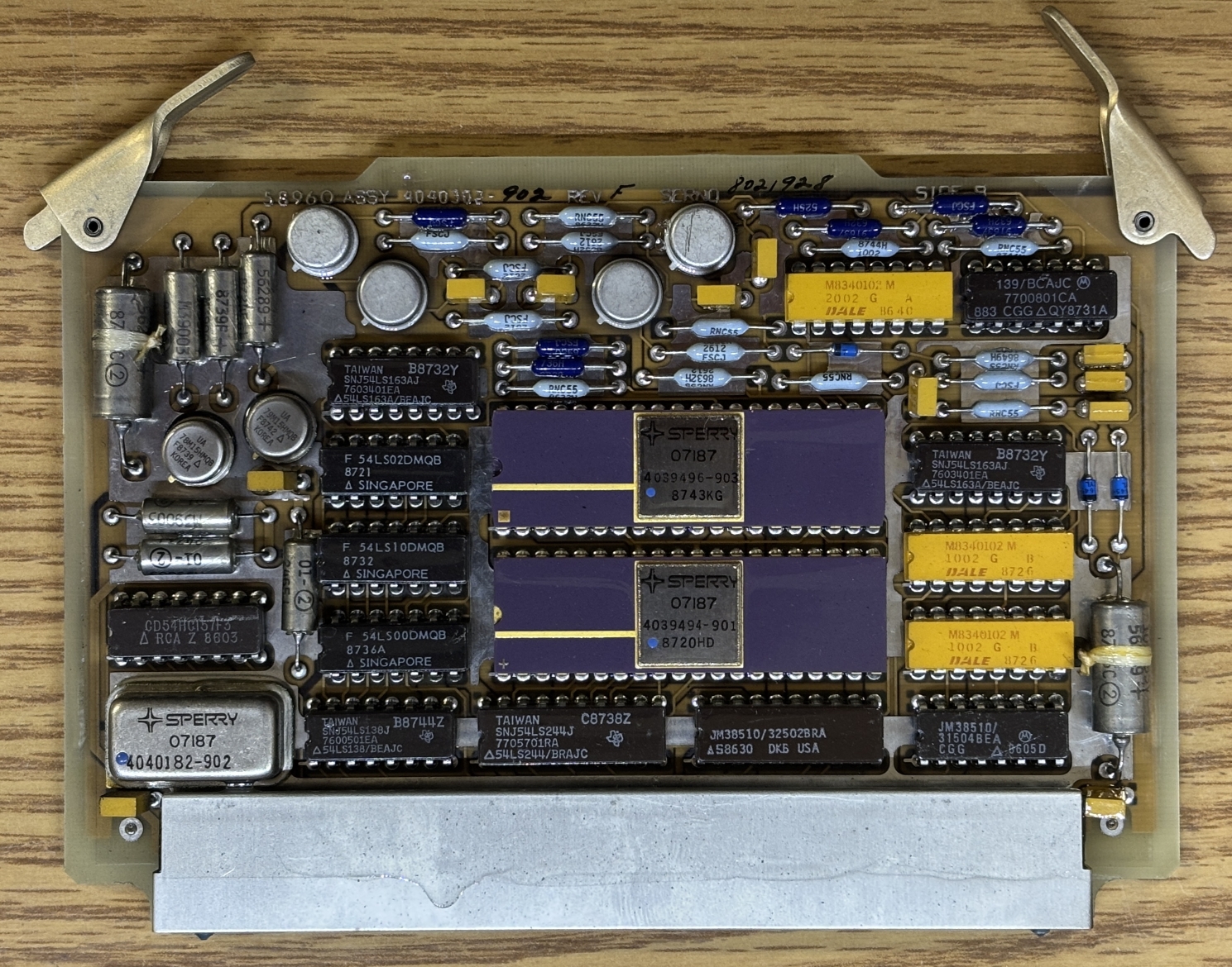
This card contains two purple ceramic DIP chips made by Sperry with part numbers of 4039496-903 and 4039494-901. We unfortunately could not find any information about these chips, they are likely custom or quite specialized. Other notable components on this board include some Fairchild 54LS00DMQB logic gates, Texas Instruments SNJ54LS163AJ counters, Texas Instruments SNJ54LS244J buffers, JM38510 latches, Motorola 7700801CA comparator, and some DALE M8340102 resistor arrays. The Sperry metal can component with a part number of 4040182-902 looks like a crystal oscillator, but we are not sure as there is no information on this part either.
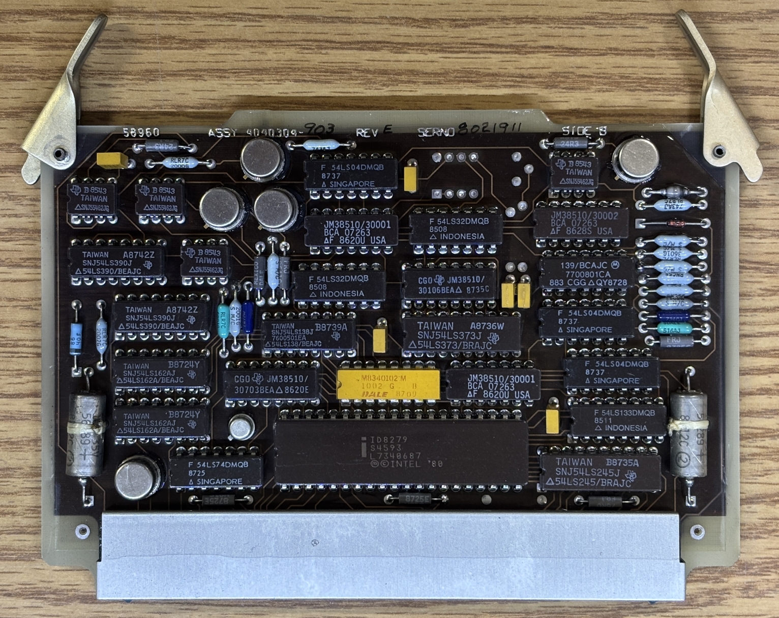
This board has an Intel 8279 keyboard display controller chip. It's a ceramic package and likely the military/industrial variant. Take note of how nearly all the chips have a small triangle or contain the prefix "SN" (if made by Texas Instruments). These designations indicate that they are Military grade, high reliability, and/or high temperature variants of the chips. This is also evident by the ceramic packages as the normal/commercial versions of many of these chips use plastic packages.
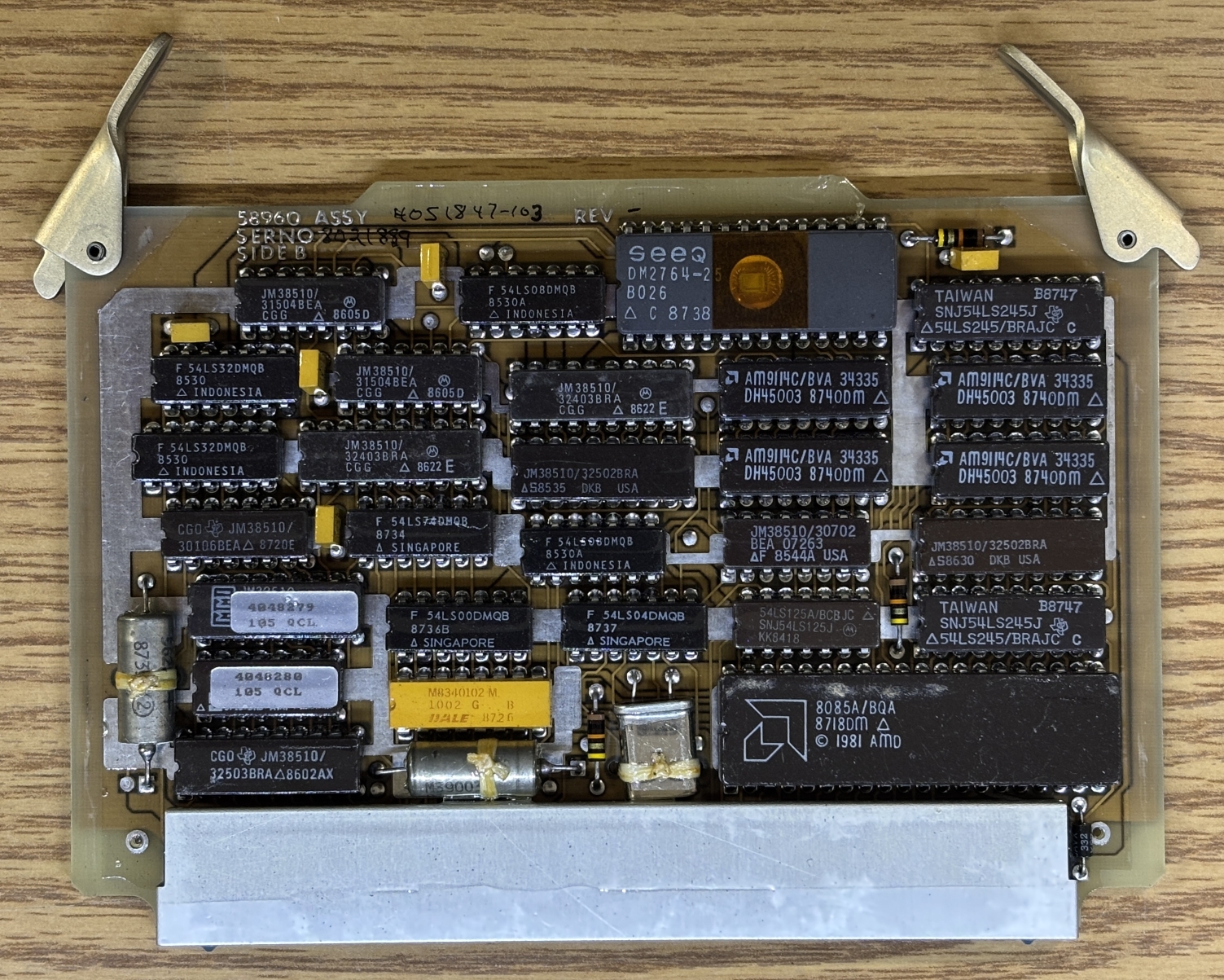
This card is pretty interesting as it contains an AMD 8085A/BQA 8-bit microprocessor along with a SEEQ DM2764-25 UV-erasable EPROM. There appears to be a crystal oscillator located next to the MCU. Also, the two chips on the left covered with silver labels may be one-time programmable logic units.
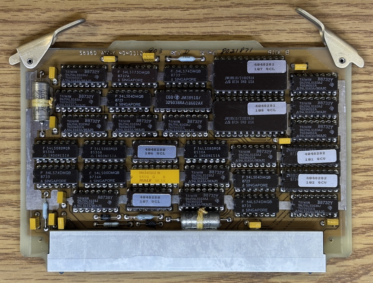
This card has has two JM38510/21002BJA IC PROMs and two AMD AM27S29 PROMs. They have no window and are therefore not erasable, you program them once and then that's it. They are read-only after that. Several of the chips on this board are similar to what could be found on the previous board.
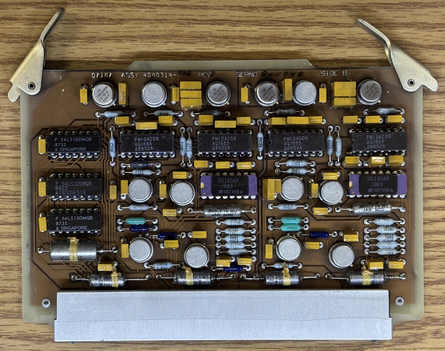
This card has several PMIDAC08 chips, which could be digital-to-analog converters (DAC). There are also some 54LS logic gates along with two purple ceramic DG190AP/883 SPDT analog JFET switches.
Lastly, this card has a single DG190AP/883 SPDT analog JFET switch and significantly more shielding/ground plane on the PCB compared to the other cards.
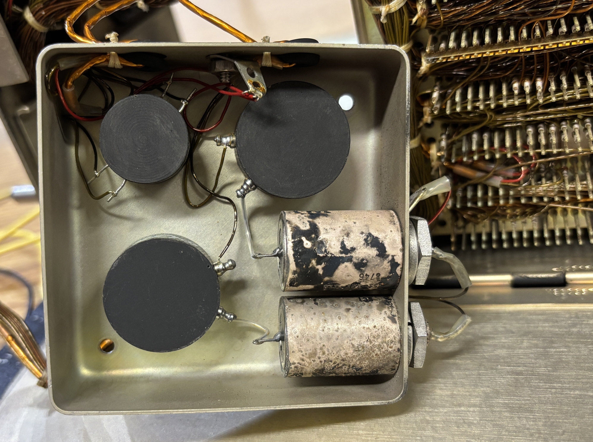
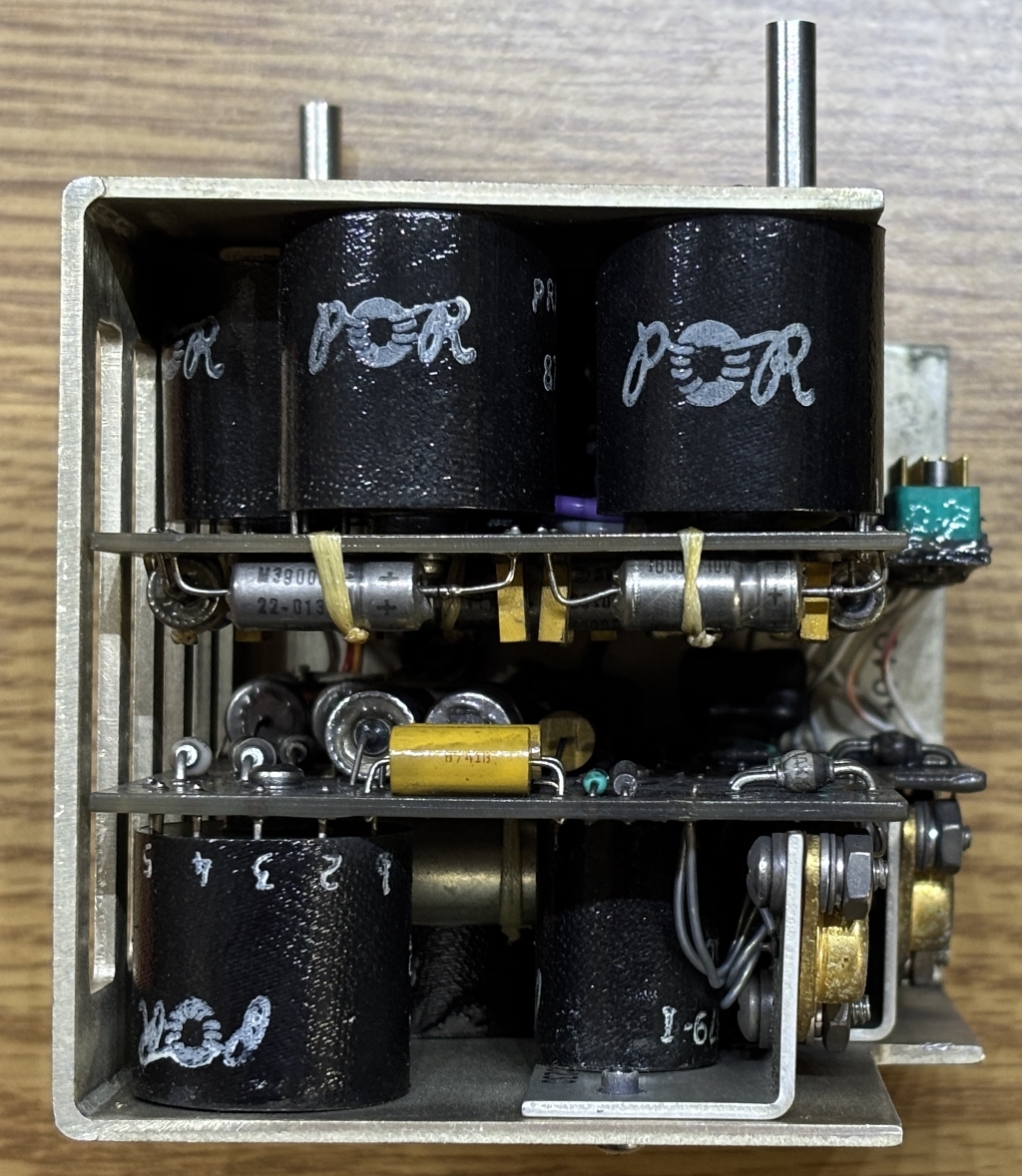
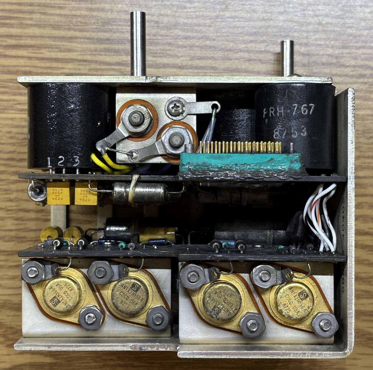
This is the A15 low voltage power supply (ASSY 4040342-902) that mounts to the frame behind the card cage. It takes the input power (115 VAC 400Hz and converts it to several lower DC voltages that are used by the digital electronics, panel indicators, and the CRT power supply and related circuitry. It is made of two boards that face inwards and are connected together by several wires. One board has a similar high-density connector that is used in other areas of the CDU. The exact details and voltages of this power supply are quite difficult to figure out due to the fact that it's mostly made up of these "POR" branded transformers, which only have part numbers and pin numbers. We searched all over for information about these transformers and found absolutely nothing. There are 4 2N5664 transistors mounted to the metal frame of the power supply.
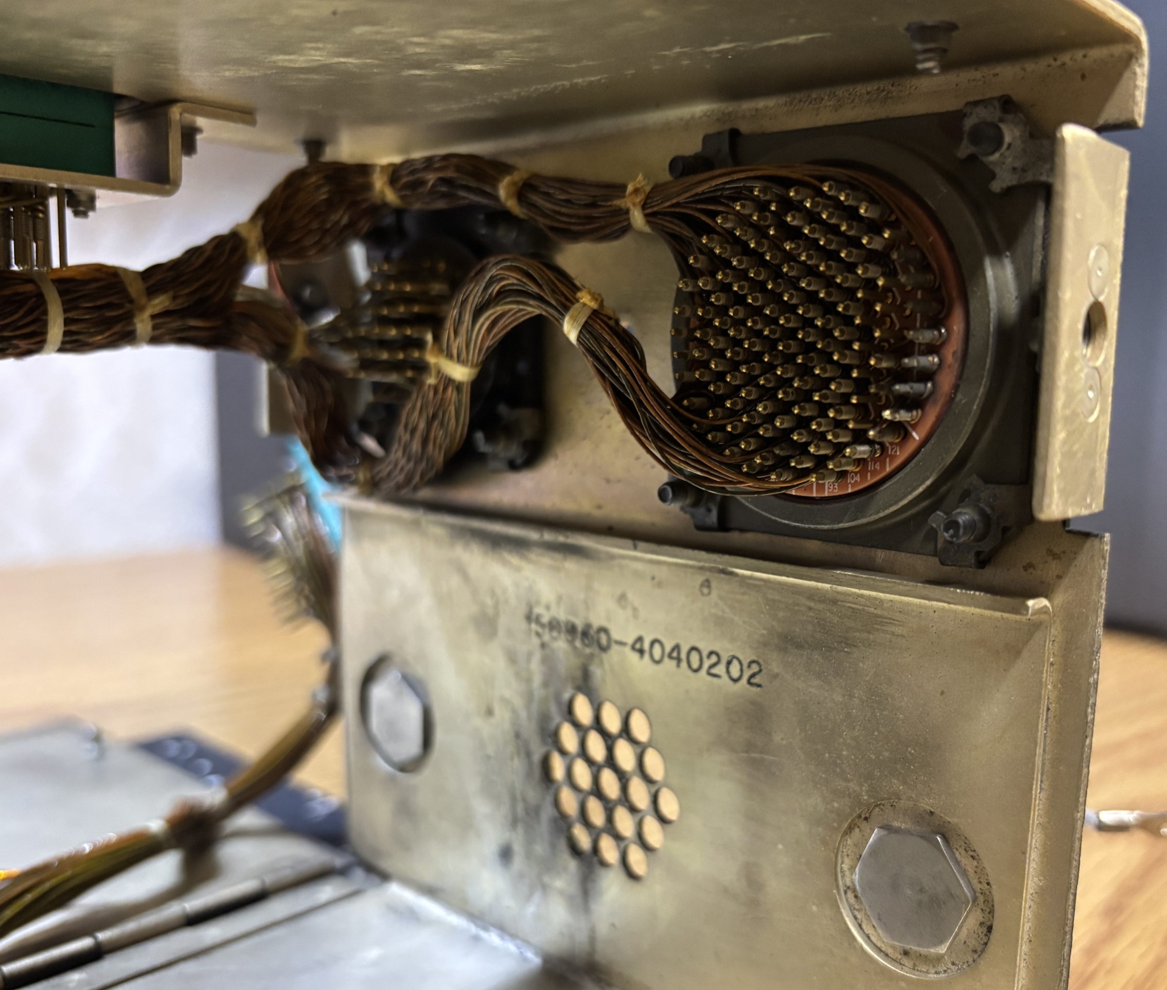
With the power supply out of the way, we can remove a metal cover to get a look at the back of the two connectors. There are quite a-lot of pins, and each wire has been wound around the pins by hand. Quite impressive workmanship.
Getting the CDU to power on took some trial-and-error and educated guesses. We originally thought it would be powered by 28V DC, but that did nothing. We identified the power pins by testing continuity to the input filtering module. This allowed us to figure out the chassis ground and two AC input pins. After examining the power supply, we figured that the only other option was 115V AC 400Hz. Luckily this turned out to be correct. The unit draws around 50 watts and it takes about 30 seconds for the CRT to warm up and come on. We originally thought it was dead or needed some sort of power on signal, but were delighted when it did eventually come on. There is no audible CRT whine. The keyboard integrity lighting is powered separately by 5V DC and was easy to figure out as the connections on the front panel for the bulbs go directly to the twist-lock connector on the back. Lastly, we used a medium-value resistor attached to the chassis ground to carefully touch pins until we found the lamp test pin, which activates the annunciators on either side of the keyboard.
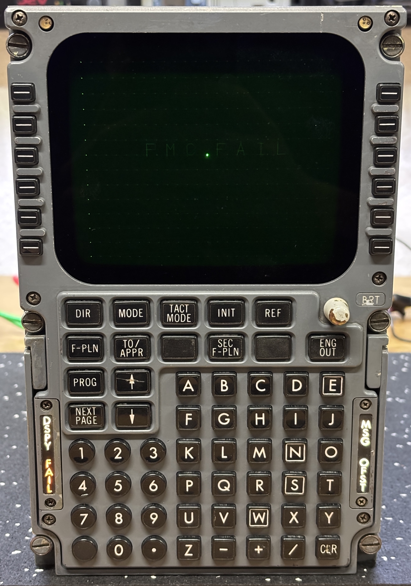
The display is quite dim and does not respond to the brightness adjustment knob or the photosensors on the top. Perhaps the brightness control depends on the flight management computer. In the image below, we grounded the lamp test pin, which illuminates the DSPY, FAIL, MSG, and OFST annunciators on the sides of the keyboard.
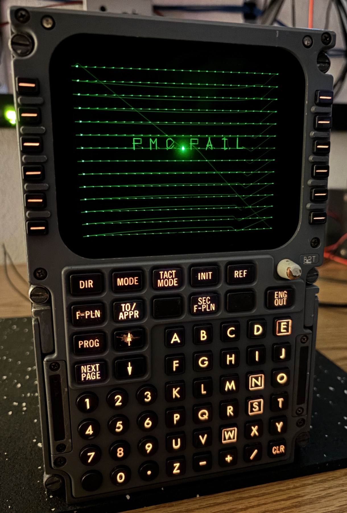
This image was taken using long exposure mode, which shows the path that the CRT driver takes to draw the image and text on the screen. On the screen, each of the 14 lines appear with a dot in place of each of the 24 characters per line. Along with this is a message displayed in the center that reads FMC FAIL. This is expected since the CDU is not connected to a flight management computer and likely assumes it has failed. It refuses to do anything else, we pressed and held down random buttons but it does not respond to anything. That's about as far as we'll go with this unit for now. Reverse-engineering the ARINC 429 digital communication buses will be quite a chore, and it's not going to even do anything until it receives valid data from an actual (or simulated) flight management computer. Our next objective for this CDU is to hijack the CRT video input and display pictures or text on it using a computer or other device capable of generating an analog video signal.
Check out the following resources below, there is not much information available on this particular CDU and the flight management system that it would communicate with, but we did find a few resources that contain relevant information. Specifically, the CDU simulator manual goes over each button and function of the CDU. The document from FedEx details the A310-300 flight management system, which includes this type of CDU. It also contains useful information regarding how the CDU and FMC communicate over ARINC 429.